Syntax:
Legacy SPI Operations
    SPIMode ( _Mode_ [, _SPIClockMode_])

    // Specfic the hardware SPI operating mode, can be MasterFast, Master, MasterSlow
    #DEFINE HWSPIMode   MasterFast

    // You can use a shared constant to set a consant with the desired SPIClockMode
    #DEFINE HWSPIClockMode  SPI_CPOL_0 + SPI_CPHA_0
AVRDX, 18FxxQxx, 18FxxK42 and 18xxFK83 microcontrollers
For HWSPI channel 0
    SPIMode ( _Mode_ , _SPIClockMode_ )

    // Specfic the hardware SPI operating mode, can be MasterUltraFast, MasterFast, Master, MasterSlow
    #DEFINE HWSPIMode   MasterUltraFast

    // You can use a shared constant to set a consant with the desired SPIClockMode
    #DEFINE HWSPIClockMode  SPI_SS_0 + SPI_CPOL_0 + SPI_CPHA_0

    // Optionally change the SPI BAUD RATE from 4000
        #DEFINE SPI_BAUD_RATE 8000

    // Optionally update the SPI baud rate register with an explicit value
    //  typical use is to entry a specific calculated value
        #DEFINE SPI_BAUD_RATE_REGISTER  55
Command Availability:
Available on Microchip PIC and AVR microcontrollers with Hardware SPI modules.
Explanation:
Mode sets the mode of the SPI module within the microcontroller. These are the possible SPI Modes:
| Mode Name | Description |
|---|---|
|
Legacy SPI Operations |
|
|
|
Master mode, SPI clock is 1/64 of the frequency of the microcontroller. |
|
|
Master mode, SPI clock is 1/16 of the frequency of the microcontroller. |
|
|
Master mode, SPI clock is 1/4 of the frequency of the microcontroller. |
|
AVRDX, 18FxxQxx, 18FxxK42 and 18xxFK83 microcontrollers |
|
|
|
SPI clock baud rate is calculated INT( ChipMHz / INT( SPI_BAUD_RATE ) / 16 * 1000) + 1. Where SPI_BAUD_RATE defaults to 4000. Also, see |
|
|
SPI clock baud rate is calculated as INT( ChipMHz / INT( SPI_BAUD_RATE ) / 4 * 1000) + 1. Where SPI_BAUD_RATE defaults to 4000. Also, see |
|
|
SPI clock baud rate is calculated as INT( ChipMHz / INT( SPI_BAUD_RATE ) / 2 * 1000) + 1. Where SPI_BAUD_RATE defaults to 4000. Also, see |
|
|
SPI1BAUD is set to 0 and therefore the SPI clock baud rate to maximum |
|
Slave Operations |
|
|
|
Slave mode |
|
|
Slave mode, with the Slave Select pin enabled. |
For Legacy microcontrollers SPI operations SPIClockMode is an optional parameter to set the mode of the SPI clock mode. This optional parameter sets both the clock polarity and clock edge.
For Specific PICs microcontrollers SPI operations SPIClockMode is a mandated parameter to set the mode of the SPI clock mode and the clock polarity bit. This parameter sets both the clock
polarity and clock edge.
There is no verification by the compiler if you do use the _SPIClockMode for the 18FxxQxx, 18FxxK42 and 18xxFK83 microcontrollers - the compiler uses the default value of SPI_SS = 0 & SPI_CPOL = 0 & SPI_CPHA = 0 The use of SPI_SS_n requires the PPS to be set. If PPS is not set then the SPI_SS will use the default value specified
in the specfic GCBASIC library.
For the _SPIClockMode_range, see the tables below:
| SPIClockMode | Description |
|---|---|
|
Legacy SPI operations |
|
|
0 |
SPI_CPOL = 0 & SPI_CPHA = 0 |
|
1 |
SPI_CPOL = 0 & SPI_CPHA = 1 |
|
2 |
SPI_CPOL = 1 & SPI_CPHA = 0 |
|
3 |
SPI_CPOL = 1 & SPI_CPHA = 1 |
|
18FxxQxx, 18FxxK42 and 18xxFK83 microcontrollers |
|
|
0 |
SPI_SS = 0 & SPI_CPOL = 0 & SPI_CPHA = 0 |
|
2 |
SPI_SS = 0 & SPI_CPOL = 1 & SPI_CPHA = 0 |
|
5 |
SPI_SS = 1 & SPI_CPOL = 0 & SPI_CPHA = 1 |
|
7 |
SPI_SS = 1 & SPI_CPOL = 1 & SPI_CPHA = 1 |
You can use a constant value or alternatively you can use constants to set the SPIClockMode as follows:
    _Legacy SPI microcontrollers_
    SPIMode ( MasterFast, SPI_CPOL_n + SPI_CPHA_n )

    _18FxxQxx, 18FxxK42 and 18xxFK83 microcontrollers_
    SPIMode ( MasterFast, SPI_SS_n + SPI_CPOL_n + SPI_CPHA_n )
Where the following parameters can be used as a calculation to set the SPIClockMode.
| Mode Name | Description |
|---|---|
|
Legacy SPI operations and AVRs |
|
|
SPI_CPOL_0 |
CPOL = 0 |
|
SPI_CPOL_1 |
CPOL = 1 |
|
SPI_CPHA_0 |
CPHA = 0 |
|
SPI_CPHA_1 |
CPHA = 1 |
|
18FxxQxx, 18FxxK42 and 18xxFK83 microcontrollers |
|
|
SPI_SS_0 |
SS = 0 Clear polarity bit |
|
SPI_SS_1 |
SS = 1 Set polarity bit |
Explicitly changing the SPI baud rate on 18FxxQxx, 18FxxK42 and 18xxFK83 microcontrollers
You can explicitly change the SPI baud rate by defining the SPI_BAUD_RATE constant as follows. This will change the default SPI baud from 4000 to the specified numeric value.
#DEFINE SPI_BAUD_RATE 8000
You can explicitly set the SPI baud rate register by defining the SPI_BAUD_RATE_REGISTER constant as follows. This will write the explicit numeric value to the SPI baud register. This overwrites any compiler
calculated value.
#DEFINE SPI_BAUD_RATE_REGISTER 55
Legacy SPI Summary:
When using SPI setting the clock frequency is completed using SPIMode, and the master must also configure the clock polarity and phase with respect to the data. Using the two options as CPOL and CPHA.
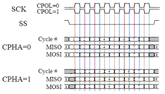
The timing diagram is shown below. The timing is further described and applies to both the master and the slave device.
When CPOL=0 the base value of the clock is zero, i.e. the active state is 1 and idle state is 0.
- For CPHA=0, data are captured on the clock’s rising edge (low→high transition) and data is output on a falling edge (high→low clock transition).
- For CPHA=1, data are captured on the clock’s falling edge and data is output on a rising edge.
When CPOL=1 the base value of the clock is one (inversion of CPOL=0), i.e. the active state is 0 and idle state is 1.
- For CPHA=0, data are captured on clock’s falling edge and data is output on a rising edge.
- For CPHA=1, data are captured on clock’s rising edge and data is output on a falling edge.
When CPHA=0 means sampling on the first clock edge and , while CPHA=1 means sampling on the second clock edge, regardless of whether that clock edge is rising or falling. Note that with CPHA=0, the data must be stable for a half cycle before the first clock cycle.
In other words, CPHA=0 means transmitting data on the active to idle state and CPHA=1 means that data is transmitted on the idle to active state edge. Note that if transmission happens on a particular edge, then capturing will happen on the opposite edge(i.e. if transmission happens on falling, then reception happens on rising and vice versa). The MOSI and MISO signals are usually stable (at their reception points) for the half cycle until the next clock transition. SPI master and slave devices may well sample data at different points in that half cycle.
This adds more flexibility to the communication channel between the master and slave.
Legacy Example:
This example demonstrates the SPI capabilities for the mega328p. The process is similar of any microcontroller..
You must set the data line as inputs and outputs.
        #chip mega328p, 16
        #option explicit
        #include <UNO_mega328p.h >

        #define SPI_HardwareSPI  'comment this out to make into Software SPI but, you may have to change clock lines

        'Pin mappings for SPI - this SPI driver supports Hardware SPI
        #define SPI_DC       DIGITAL_8          ' Data command line
        #define SPI_CS       DIGITAL_4          ' Chip select line
        #define SPI_RESET    DIGITAL_9          ' Reset line

        #define SPI_DI       DIGITAL_12          ' Data in | MISO
        #define SPI_DO       DIGITAL_11          ' Data out | MOSI
        #define SPI_SCK      DIGITAL_13          ' Clock Line

        dir SPI_DC    out
        dir SPI_CS    out
        dir SPI_RESET out
        dir SPI_DO    Out
        dir SPI_DI    In
        dir SPI_SCK   Out

        'If DIGITAL_10 is NOT used as the SPI_CS (sometimes called SS) the port must and output or set as input/pulled high with a 10k resistor.
        'As follows:
        'If CS is configured as an input, it must be held high to ensure Master SPI operation.
        'If the CS pin is driven low by peripheral circuitry when the SPI is configured as a Master with the SS pin defined as an input, the
        'SPI system interprets this as another master selecting the SPI as a slave and starting to send data to it!
        'If CS is an output SPI communications will commence with no flow control.
        dir DIGITAL_10 Out


        dim outbyte, inbyte as byte


        #DEFINE HWSPICLOCKMODE  SPI_CPOL_0 + SPI_CPHA_0
        SPIMode ( MasterFast, HWSPICLOCKMODE )


       do
        set SPI_CS OFF//  Select line
        set SPI_DC OFF//  Send Data if off, or, Data if On
        SPITransfer ( outbyte, inbyte )
        set SPI_CS ON//   Deselect Line
        set SPI_DC ON
        wait 10 ms
       loop
18FxxQxx, 18FxxK42 and 18xxFK83 microcontrollers SPI Summary:
When using SPI setting the clock frequency is completed using SPIMode, and the master must also configure the clock polarity and phase with respect to the data. Using the three options as CPOL, CPHA and SS.
The timing diagram is as shown in the prevsious section that impacts CPOL and CPHA.
If you have set the PPS for SPI1SSPPS then control of the SPI SS ( also know as CS / ChipSelect) is automatically controlled by the SPI transmission.
- Example:*
    #CHIP 18F16Q41,64

    #STARTUP InitPPS, 85
    #DEFINE PPSToolPart 18F16Q41

    // Use PPS to assign SPI capabilities to specific ports
    SUB InitPPS
        SPI1SDIPPS = 0x000C
        RB6PPS = 0x001B
        SPI1SCKPPS = 0x000E
        RB5PPS = 0x001C
        RC6PPS = 0x001D
        SPI1SSPPS = 0x0016
    END SUB


    // Optionally change the SPI BAUD RATE from 4000
        // #DEFINE SPI_BAUD_RATE 8000

    // Optionally update the SPI baud rate register with an explicit value
    //  typical use is to entry a specific calculated value
        // #DEFINE SPI_BAUD_RATE_REGISTER  1

    // Specfic the hardware SPI operating model
    // Can be MasterUltraFast, MasterFast, Master, MasterSlow
    #DEFINE HWSPIMode   MasterUltraFast

    // You can use a shared constant to set a consant with the desired SPIClockMode
    #DEFINE HWSPIClockMode  SPI_SS_0 + SPI_CPOL_0 + SPI_CPHA_0

    // Call SPIMode
    SPIMode (HWSPIMode,  HWSPIClockMode )

    // Define the GCBASIC required SPI port constants.
    // Must match any PPS defined.
    #DEFINE SPI_SCK   PORTB.6
    #DEFINE SPI_DO    PORTB.5
    #DEFINE SPI_DI    PORTB.4
    #DEFINE SPI_DC    PortC.1
    #DEFINE SPI_CS    PortC.6
    #DEFINE SPI_RESET PortC.2

    DO
        // Send 0x75 via SPI over and over again...
        FastHWSPITransfer 0x75
    LOOP
See also SPITransfer,FastHWSPITransfer
