Syntax:
The SPI interface allows for the transmission and receiption of data simultaneously on two lines (MOSI and MISO).
The Clock polarity (CPOL) and clock phase (CPHA) are the main parameters that define a clock format to be used by the SPI bus. Depending on CPOL parameter, SPI clock may be inverted or non-inverted. CPHA parameter is used to shift the sampling phase. If CPHA=0 the data are sampled on the leading (first) clock edge. If CPHA=1 the data are sampled on the trailing (second) clock edge, regardless of whether that clock edge is rising or falling.
CPOL=0, CPHA=0
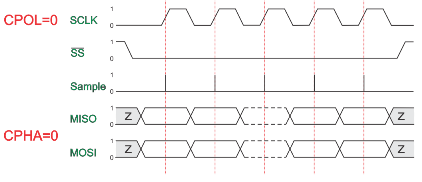
The data must be available before the first clock signal rising. The clock idle state is zero. The data on MISO and MOSI lines must be stable while the clock is high and can be changed when the clock is low. The data is captured on the clock’s low-to-high transition and propagated on high-to-low clock transition.
CPOL=0, CPHA=1
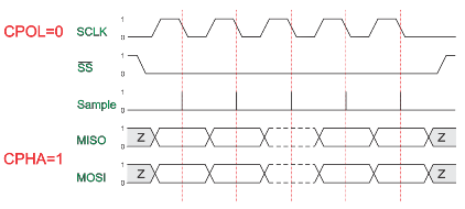
The first clock signal rising can be used to prepare the data. The clock idle state is zero. The data on MISO and MOSI lines must be stable while the clock is low and can be changed when the clock is high. The data is captured on the clock’s high-to-low transition and propagated on low-to-high clock transition.
CPOL=1, CPHA=0
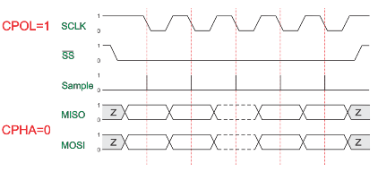
The data must be available before the first clock signal falling. The clock idle state is one. The data on MISO and MOSI lines must be stable while the clock is low and can be changed when the clock is high. The data is captured on the clock’s high-to-low transition and propagated on low-to-high clock transition.
CPOL=1, CPHA=1
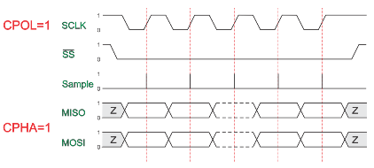
The first clock signal falling can be used to prepare the data. The clock idle state is one. The data on MISO and MOSI lines must be stable while the clock is high and can be changed when the clock is low. The data is captured on the clock’s low-to-high transition and propagated on high-to-low clock transition.
Key Commands
    // Set the mode
    SPIMode  ( _Mode_ [, SPIClockMode]) //Legacy SPI
    SPIMode  ( _Mode_ , SPIClockMode)   //18FxxQxx, 18FxxK42 and 18xxFK83 microcontrollers

    // Send bytge and receive data byte
    SPITransfer (  _OutByte_, _InByte_ )

    // Send data byte
    FastHWSPITransfer( _OutByte_ )

    // USe MASTERSLOW | MASTER | MASTERFAST | MASTERULTRAFAST for specific AVRs only | MasterSSPADDMode for specific PICs SSPADD support

    // The system constant `HWSPIMode` defaults to MASTERFAST when microcontroller frequency less or equal to 32 mhz
    // Defaults to MASTER when microcontroller frequency more than 32 mhz.
    // To change use the following method
    #define HWSPIMode MASTERULTRAFAST
The GCBASIC used the microcontrollers hardware module for SPI. The example below shows an implementation of Hardware and Software SPI. Software SPI allows for a greater choice of ports to be used to control the SPI operations.
To use a second SPI hardware module use the suffix 2, as follows:
    // Set the mode
    SPIMode2  ( _Mode_ [, SPIClockMode]) //Legacy SPI
    SPIMode2  ( _Mode_ , SPIClockMode)   //18FxxQxx, 18FxxK42 and 18xxFK83 microcontrollers

    // Send bytge and receive data byte
    SPITransfer2 (  _OutByte_, _InByte_ )

    // Send data byte
    FastHWSPITransfer2( _OutByte_ )
Example
This example demonstrates the SPI capabilities for the mega328p. The process is similar of any microcontroller..
This example show using the hardware SPI option and a sofware SPI option.
Using hardware SPI mode - make sure the #define SPI_HardwareSPI is not commented out.
Using software SPI mode - comment out #define SPI_HardwareSPI. The example code will then use software SPI.
Using multiple SPI devices
There will be use cases were you need to use more than one SPI target device at a time. In such cases the device defined for SPI must be inserted in your program for each device.
As an example using e-Paper and SRAM at the same time, with an hardware SPI would require #define SPISRAM_HARDWARESPI and #define EPD_HardwareSPI.
Obviously, when all SPI devices use the same SPI lines, you must select one device at a time by setting SPI Chip Select line
to OFF for the specific target SPI device, and you must set ON the SPI Chip Select line for any other SPI device - this is a normal convention of SPI usage. This is not specific to
GCBASIC..
Code overview
For more code examples see the demonstrations and the SPIMODE Help page.
In this example InitSPIMode calls SPIMode. If needed, when hardware mode, and set the port directions.
The sub SendByteviaSPI is called to handle whether to call the Hardware or use Software (bit-banging) SPI.
        #chip mega328p, 16
        #option explicit
        #include <UNO_mega328p.h >

        #define SPI_HardwareSPI  'comment this out to make into Software SPI but, you may have to change clock lines

        'Pin mappings for SPI - this SPI driver supports Hardware SPI
        #define SPI_DC       DIGITAL_8          ' Data command line
        #define SPI_CS       DIGITAL_4          ' Chip select line
        #define SPI_RESET    DIGITAL_9          ' Reset line

        #define SPI_DI       DIGITAL_12          ' Data in | MISO
        #define SPI_DO       DIGITAL_11          ' Data out | MOSI
        #define SPI_SCK      DIGITAL_13          ' Clock Line

        dir SPI_DC    out
        dir SPI_CS    out
        dir SPI_RESET out
        dir SPI_DO    Out
        dir SPI_DI    In
        dir SPI_SCK   Out

        'If DIGITAL_10 is NOT used as the SPI_CS (sometimes called SS) the port must and output or set as input/pulled high with a 10k resistor.
        'As follows:
        'If CS is configured as an input, it must be held high to ensure Master SPI operation.
        'If the CS pin is driven low by peripheral circuitry when the SPI is configured as a Master with the SS pin defined as an input, the
        'SPI system interprets this as another master selecting the SPI as a slave and starting to send data to it!
        'If CS is an output SPI communications will commence with no flow control.
        dir DIGITAL_10 Out

        DIM byte1 As byte
        DIM byte2 As byte
        DIM byte3 As byte

        byte1 = 100 ' temp values (will come from potentiometer later)
        byte2 = 150
        byte3 = 200

        InitSPIMode


        do forever
            set SPI_CS OFF;
            set SPI_DC OFF;
            SendByteviaSPI (byte1)
            set SPI_CS ON;
            set SPI_DC ON

            set SPI_CS OFF;
            set SPI_DC OFF;
            SendByteviaSPI (byte2)
            set SPI_CS ON;
            set SPI_DC ON

            set SPI_CS OFF;
            set SPI_DC OFF;
            SendByteviaSPI (byte3)
            set SPI_CS ON;
            set SPI_DC ON

            wait 10 ms
        loop


    sub InitSPIMode

          #ifdef SPI_HardwareSPI
              SPIMode ( MasterFast, SPI_CPOL_0 + SPI_CPHA_0 )
          #endif

          set SPI_DO OFF;
          set SPI_CS ON;   therefore CPOL=0
          set SPI_DC ON;   deselect

    End sub

    sub  SendByteviaSPI( in SPISendByte as byte )

      set SPI_CS OFF
      set SPI_DC OFF;

      #ifdef SPI_HardwareSPI
         FastHWSPITransfer  SPISendByte
         set SPI_CS ON;
         exit sub
      #endif

      #ifndef SPI_HardwareSPI
      repeat 8

        if SPISendByte.7 = ON  then
          set SPI_DO ON;
        else
          set SPI_DO OFF;
        end if
        SET SPI_SCK On;           ; therefore CPOL=0 ==ON, and, where CPOL=1==ON
        rotate SPISendByte left
        set SPI_SCK Off;          ; therefore CPOL=0  =OFF, and, where CPOL=1==OFF

      end repeat
      set SPI_CS ON;
      set SPI_DO OFF;
      #endif

    end Sub
See also SPIMode,SPITransfer,FastHWSPITransfer
