Syntax:
Pot pin, outputCommand Availability:
Available on all microcontrollers.
Explanation:
Pot makes it possible to measure an analog resistance with a digital port, with the addition of a small capacitor. This is the
required circuit:
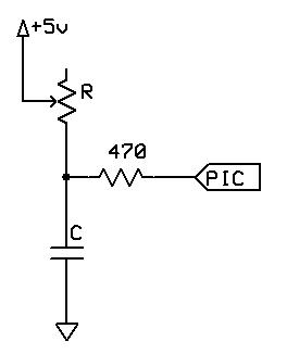
The command works by using the microcontroller pin to discharge the capacitor, then measuring the time taken for the capacitor to charge again through the resistor.
The value for the capacitor must be adjusted depending on the size of the variable resistor. The charging time needs to be approximately 2.5 ms when the resistor is at its maximum value. For a typical 50 k potentiometer or LDR, a 50 nf capacitor is required.
This command should be used carefully. Each time it is inserted, 20 words of program memory are used on the chip, which as a rough guide is more than 15 times the size of the Set command.
pin is the port connected to the circuit. The direction of the pin will be dealt with by the Pot command.
output is the name of the variable that will receive the value.
Example 1:
    'This program will beep whenever a shadow is detected
    'A potentiometer is used to adjust the threshold

    #chip 16F628A, 4

    #define ADJUST PORTB.0
    #define LDR PORTB.1
    #define SoundOut PORTB.2

    Dir SoundOut Out

    Do
        Pot ADJUST, Threshold
        Pot LDR, LightLevel
        If LightLevel > Threshold Then
            Tone 1000, 100
        End If
    Loop
Example 2:
This program is an implementation of the capacitor and resistor principle using the chips internal capacitor and the internal pullup resistor.
The will test the state of the GPIO.3 port by using these internal components, and, after the charge state has been complete the LED PWM will represent the detected value of signal on the GPIO.3 port.
It should be note that GCBASIC will set the DIRection of GPIO.2 and GPIO.3 automatically. And, this solution is specific
to the 12F509 and therefore the 12F509 register called NOT_GPPU may be different on another chip.
    #chip 12F509
    #option Explicit

      ;Defines (Constants)
      #define PWM_Out1 GPIO.2

      ;Variables
      Dim TimeCount As byte
      Dim OPTION_REG as byte

      Do Forever

          NOT_GPPU = Off
          Wait 1 ms
          NOT_GPPU = On
          TimeCount = 0

          'Do while held high by the internal capacitance
          Do While GPIO.3 = 1

            TimeCount = TimeCount + 1
            If TimeCount = 255 Then
                Exit Do
            End If

          Loop

          PWMout 1, TimeCount, 5

      Loop
See also ladyada.net/library/rccalc.html or cvs1.uklinux.net/cgi-bin/calculators/time_const.cgi for calculating capacitor value. These sites are not associated with GCBASIC.
