About Analog to Digital Conversion
The analog to digital converter (ADC or A/D) module support is implemented by GCBASIC to provide 8-bit, 10-bit and 12-bit Single channel measurement mode and Differential Channel Measurement mode.
GCBASIC configures the analog to digital converter clock source, the programmed acquisition time and justification of the response byte, word or integer (as defined in the GCBASIC method).
Normal or Single channel measurement mode
The Single channel measurement mode is the default method for reading the ADC port. The positive input is attached to suitable device (a light sensor or adjustable resistor) and the command ReadADC, ReadADC10, ReadADC12 with return a byte, word or word value respectively.
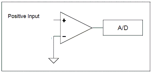
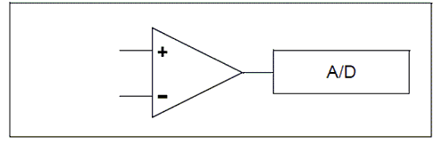
The A/D module on most microcontrollers only supports single-ended mode. Single channel mode uses a single A/D port and the returned Value represents the difference between the voltage on the analog pin and a fixed negative reference which is usually ground or Vss.
The syntax for single-ended A/D is Returned_Value = ReadAD(Port)
Example
Print ReadAD10(AN3)
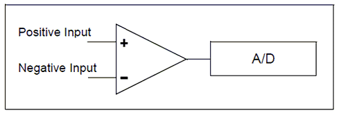
Differential channel measurement mode
Some of the in the Microchip PIC family of devices also support differential analog to digital conversion. With differential conversion, the differential voltage between two channels is measured and converted to a digital value. The returned value can be either positive or negative (therefore an integer value).
When configured to differential channel measurement mode, the positive channel is connected to the defined positive analog pin (ANx), and the negative channel is connected to the defined negative analog pin. These two pins are internally connected (within the microcontroller) to a unity gain differential amplifier and once the amplifier has completed the comparison the result is returned as an integer.
The positive channel Input is selected using the CHSx bits and the negative channel input is selected using the CHSNx bits. These bits are managed by GCBASIC. The programmer only needs to supply the correct analog pin designators in the ReadADx commands.
The 12-bit returned result is available on the ADRESH and ADRESL registers which is returned by the GCBASIC methods as an integer variable.
Some Microchip PIC microcontrollers have differential A/D modules and support differential Mode as well as 12-Bit A/D. With DIfferential mode the returned value can be either a positive or negative number that represents the voltage differential between the two A/D ports.
The syntax for differential A/D is ReadAD( PositiveANPort , NegativeANPort ). Note: if "negative port" is omitted readAd() will perform a single-ended read on the positive AN port.
Example
Print ReadAD12( AN3, An4 )
Using Voltage Reference
Voltage references come in many forms and offer different features across the PICs, AVR and LGTs microcontrollers. But, in the end, accuracy and stability are a voltage reference’s most important features, as the main purpose of the reference is to provide a known output voltage. Variation from this known value is an error. Therefore, it is useful to use the internal voltage reference provided within the microcontroller.
To use a voltage reference source for ADC operation sett the AD_REF_SOURCE constant to your chosen source.
The defaults to the VCC pin, and there for the constant is set by default to AD_REF_AVCC.
The voltage reference is specific to the microcontroller but the options are as follows:
| AD_REF_SOURCEConstant | Reference Voltage |
|---|---|
|
AD_REF_AVCC |
VCC supplied Voltage |
|
AD_REF_1024 |
1.024v internal reference source |
|
AD_REF_2048 |
2.048v internal reference source |
|
AD_REF_4096 |
4.096v internal reference source |
|
AD_REF_AREF |
Extenal voltage reference source |
|
AD_REF_256 |
AD_REF_256 for ATMegas |
Optimising GCBASIC Code
GCBASIC supports a wide range of A/D modules and the supporting library addresses up to 34 channels. To reduce the size of the code produced you can define which channels are specifically supported. See Optimising ADC code for more details.
See also ReadAD, ReadAD10 and ReadAD12
For the latest Microchip PIC microcontrollers that support Differential and 12-bit A/D please refer to Microchip MAPS or the microcontrollers datasheet.
