Using connection mode 3:
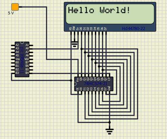
This method uses a Data and a Clock line via a shift register to control the LCD display plus an Enable line. This method is used when the LCD is connected through a shift register IC using a LS74574.
This connection method is also called a 3-wire connection.
The diagram below shows a method to connect the LCD to a microcontroller.
Relevant Constants:
Specific constants are used to control settings for the Liquid Crystal Display routines included with GCBASIC. To set these constants the main program should specific constants to support the connection mode using #define. When using 3-bit mode only three constants must be set.
| Constant Name | Controls | Default Value |
|---|---|---|
|
|
The I/O mode. |
|
|
|
The data pin used in 3-bit mode. |
Mandated |
|
|
The clock pin used in 3- bit mode. |
Mandated |
|
|
The enable pin used in 3- bit mode. |
Mandated |
Example:
    #chip 16f628a, 4
    #option explicit

    ;Setup LCD Parameters
    #define LCD_IO 3

    'Change ports as necessary
    #define LCD_DB     PORTb.3            ; databit
    #define LCD_CB     PORTb.4            ; clockbit
    #define LCD_EB     PORTa.0            ; enable bit

      Dim BV as Byte


    'Program Start

     PRINT "GCBASIC"
     Locate 1,0
     PRINT "@2021"
     Wait 4 s

      DO Forever
           CLS
           WAIT 2 s
           PRINT "Test LCDHex "
           wait 3 s
           CLS
           wait 1 s


       for bv = 0 to 16
         locate 0,0
         Print "DEC " : Print BV
         locate 1,0
         Print "HEX "
         LCDHex BV
         Locate 1, 8
         LCDHEX BV, LeadingZeroActive

         wait 500 ms
       next
           CLS
           wait 1 s
           Print "END TEST"
      LOOP
See the separate sections of the Help file for the specifics of each Connection Mode.
For more help, see LCD_IO 0, LCD_IO 1, LCD_IO 2_74xx164, LCD_IO 2_74xx174, LCD_IO 4, LCD_IO 8, LCD_IO 10 or LCD_IO 12
