Introduction
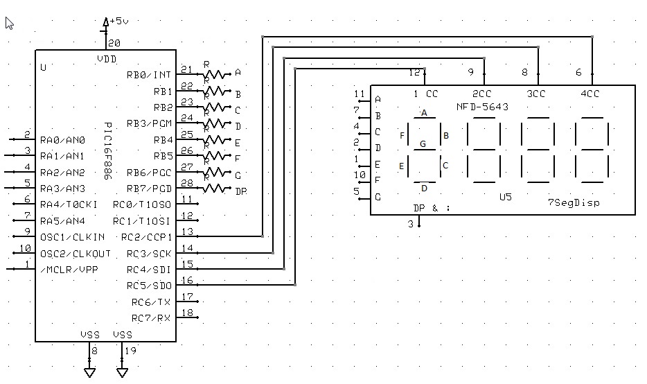
The GCBASIC 7 segment display methods make it easier for GCBASIC programs to display numbers and letters on 7 segment LED displays.
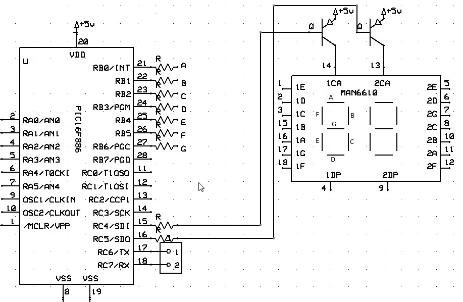
The GCBASIC methods support up to four digit 7 segment display devices, common anode/cathode and inversion of the port logic to support driving the device(s) via a transistor.
There are three ways that the 7 segment display routines can be set up.
| Method | Description |
|---|---|
|
1 |
Connect the microcontroller to the 7 segment display (via suitable resistors) using any eight output bits. Use |
|
2 |
Connect the microcontroller to the 7 segment display (via suitable resistors) using whole port (8 bits) of the microcontroller. This implies the connections are consectutive in terms of the 8 output bits of the port. Use the This method will generate the most efficient code. |
|
3 |
Connect the microcontroller to the 7 segment display (via suitable resistors) using whole port (8 bits) of the microcontroller. This implies the connections are consectutive in terms of the 8 output bits of the port. Use the |
The GCBASIC methods assume the 7 segment display(s) is to be connected to a common parallel bus with a Common Cathode. See the sections Common Cathode and Common Anode for examples of using GCBASIC code to control these different configurations
Shown below are the differing constants that must be set for the three connectivity options.
| Index | Method | Description | Constants | Default Value |
|---|---|---|---|---|
|
1 |
|
|||
|
|
Specifies the output pin (output bit) used to control a specific segment of the 7 segment display. There are seven constants that must be specified.
Typical commands are:
|
Must be specified to use this connectivity option. |
||
|
|
Specifies the output pin (output bit) used to control the decimal point on the 7 segment display. Typical commands are:
|
Optional. |
||
|
|
Specifies the output pin (output bit) used to control a specific 7 segment display. These constants are used to control the specific 7 segment display being addresses. Typical commands are:
|
A valid output pin (output bit) must be specified. Must be specified to use this connectivity option. |
||
|
2 |
|
|||
|
|
Specifies the output port used to control the 7 segment display. Port.bit >> Segment port.0 >> A port.1 >> B port.2 >> C port.3 >> D port.4 >> E port.5 >> F port.6 >> G |
Can be Where Must be specified to use this connectivity option. |
||
|
|
Specifies the output command used to select a specific 7 segment display addressed by Used to control output pin (output bit) when several displays are multiplexed. Typical commands are:
|
Can be Must be specified to use this connectivity option. |
||
|
|
An optional command to specify the output command used to deselect a specific 7 segment display addressed by Used to control output pin (output bit) when several displays are multiplexed. Typical commands are: |
Can be |
||
|
3 |
|
|||
|
|
Specifies the output port used to control the 7 segment display. Port.bit >> Segment port.0 >> A port.1 >> B port.2 >> C port.3 >> D port.4 >> E port.5 >> F port.6 >> G |
Can be Where Must be specified to use this connectivity option. |
||
|
|
Specifies the output command used to select a specific 7 segment display addressed by Typical commands are: |
Must be specified to use this connectivity option. Can be specified as |
Example 1:
        'A Common Cathode 7 Segment display  2 digit example
        #chip 16F886, 8

        'support for Common Anode
        '#DEFINE 7SEG_COMMONANODE

        'support for pfet or pnp high side drivers
        '#DEFINE 7SEG_HIGHSIDE

        ' ----- Constants
        'You need to specify the port settings
        'by one of the following three methods
        'The Directions of the ports are automaically set according to the defines

        'METHOD 1
        'Define individual port pins for segments and selects

        #DEFINE DISP_SEG_A PORTB.0
        #DEFINE DISP_SEG_B PORTB.1
        #DEFINE DISP_SEG_C PORTB.2
        #DEFINE DISP_SEG_D PORTB.3
        #DEFINE DISP_SEG_E PORTB.4
        #DEFINE DISP_SEG_F PORTB.5
        #DEFINE DISP_SEG_G PORTB.6
        #DEFINE DISP_SEG_DOT PORTB.7 '' available on some displays as dp or colon

        #DEFINE DISP_SEL_1 PORTC.5
        #DEFINE DISP_SEL_2 PORTC.4

        'METHOD 2  Define DISPLAYPORTA (B,C,D) for up to 4 digit display segments
        'Define DISPSELECTA (B,C,D) for up to 4 digit display selects

        '#DEFINE DISPLAYPORTA PORTB   ' same port name can be assigned
        '#DEFINE DISPLAYPORTB PORTB

        '#DEFINE DispSelectA Set portC.5 off
        '#DEFINE DispSelectB Set portC.4 off
        '#DEFINE DispDeSelectA Set portC.5 on
        '#DEFINE DispDeSelectB Set portC.4 on

        'METHOD 3  Define DISPLAYPORTA (B,C,D) for up to 4 digit display segments
        'Define port pins for the digit display  selects

        '#DEFINE DISPLAYPORTA PORTB
        '#DEFINE DISPLAYPORTB PORTB

        '#DEFINE DISP_SEL_1 PORTC.5
        '#DEFINE DISP_SEL_2 PORTC.4


        Dim Message As String
        Message = " HAPPY HOLIDAYS  "
        Do
            For Counter = 1 to len(Message)-1
            Repeat 50
                Displaychar 1, Message(Counter)
                wait 3 ms
                DisplayChar 2, Message(Counter+1)
                wait 3 ms

            End Repeat
            Wait 100 ms
            Next
        Loop

Also, see DisplayChar, DisplayValue

