Introducing GCBASIC
Hello, and welcome to GCBASIC help. This help file is intended to provide you insights and knowledge to use GCBASIC.
For information on installing GCBASIC and several other programs that may be helpful, please see Getting Started with GCBASIC
http://gcbasic.sourceforge.net/starting.html
If you are new to programming, you should try the GCBASIC demonstration programs these explains everything in a step-by-step manner, and assumes no prior knowledge.
If you have programmed in another language, then the demonstration files on GitHub ( or within your installation ) and this command reference may be the best place to start.
If there is anything else that you need help on, please visit the GCBASIC forum
http://sourceforge.net/forum/?group_id=169286
Using GCBASIC
Need to compile a program with GCBASIC, but don’t know where to begin? Try these simple instructions:
- Complete the installation using the default values - select all the programmers but not the portable mode.
- The installer will automatically start the IDE.
- When a GCBASIC source file is opened, check out the “GCB tools” menu ( IDE Tools / GCB tools ) - through this menu you can access the oneclick commands. Or try the right mouse button - this will access the same options.
- The IDE Tools… commands (function keys F5 - F8) starts a GCBASIC utility which calls the batchfiles for compiling sourcecode and programming
("flashing")(1) the target microcontroller. You have to select the appropriate programmer in “Edit Programmer Preferences” ( IDE Tools / GCB tools / Edit Programmer Preferences or by pressing Ctrl+Alt+E ). Find your programmer in the list and drag it to the top beneath the heading “Programmers to use (in order)”. GCBASIC will now attempt to flash the microcontroller with that programmer first when you click on "Make HEX and FLASH" ( F5 ) or "FLASH previous made hexfile" ( F8 ).
- In the unlikely event that your programmer is not listed you can add it by pressing “Add…” in “Edit Programmer Preferences”. You would have to know the working directory and command line options etc. for the programmer. See the help tips at the bottom by clicking on the fields.
- For project-specific flashing you can edit the current programmers in “Edit Programmer Preferences” to suit your needs by clicking on “Edit…”. Use the “Use If:” parameter to choose programmer preferences. See the help tips. The chip model is autodetected by the IDE for use in “Use IF:” or in command line options etc.
- Some programmers use a .hex file to "flash" the microcontroller. By selecting "Make HEX" ( F5 ), GCBASIC will compile the program and make a .hex file in the same directory as the GCBASIC file. This method can also be used to check for errors in the GCBASIC program before flashing.
- Included programmer software is:
— Avrdude for AVR,
— PICPgm for PIC,
— PicKit2 and PicKit3
— TinyBootLoader+
— Arduino
— Northern Software Programmer
— Microchip Xpress Board and many, many more.
(1) You need a suitable programmer to do this, and instructions should be
included with the programmer on how to download and connect the hardware to the microcontroller.
Programmer Preferences
The “Programmer Preferences” is a software tool to control and set-up the different programmers. See below:
When using GC Code at the IDE
Select Terminal/Run Task or press function <F4> to see the menu
Or, when using GC Code at the IDE
Select the drop down menu to see the menu
When using SynWrite at the IDE
PIC users and Beginners: Start Here
Welcome to GCBASIC. This document is especially important for experienced PIC users moving from MPASM or C so please spend a few seconds here before you start. It could save you hours of frustration.
As a PIC user most of us are conditioned, regardless of the Assembler or Compiler, to reach for the devices data sheet first and try to work out how to setup the Oscillator, interrupt vectors and Configuration bits.
Do not DO IT. read this document first as it will give you some great insights. For the basic operation the only setup and configuration required for a GCBASIC program is the name of the target Device i.e. #Chip 16f1619. That is it, honestly, GCBASIC will do the rest and will determine the optimal Oscillator settings, interrupt vectors, Configuration bits etc
Next we would start deciding on and including the Device files and libraries that we intend to use. STOP. Let GCBASIC decide. GCBASIC is creating Portable Code, it doesn’t care if you use a PIC12, PIC18 or an ATmega328. You write in BASIC and at compile time GCBASIC will decide which core libraries to include based on the instructions you have used and the target device you specified in the #chip statement.
Finally we would decide on the pins to use, their port names, which register bits are needed to make them inputs or outputs and override any Analog function if a digital function is desired.
Again, I say let GCBASIC DO IT……… Dir PortC.0 In - Will set Pin RC0 to a Digital Input. There is no need to manually set the TRIS register or see if there is an associated ADCON bit to set or clear.
Putting it all together: An example GCBASIC program.
    #Chip 16f1619

    #Define LED PortC.0

    Dir LED Out

    Do
      LED = !LED
      Wait 500 ms
    Loop
That is it. If you have an LED attached to PortC.0 (LED DS1 on the Low Pin Count Board that shipped with the PICKit 2 or PICKit 3 programmer). It will start to Blink confirming that you have a working microcontroller and hardware.
To change target device or family just change the #Chip Entry along with the Pin you have the LED on and recompile. it Really IS as Simple as that to get started in GCBASIC.
You can manually override GCBASIC and set every register, every flag, every BIT, every Configuration ‘Fuse’ and every vector if you wish, but why bother doing it upfront? Rather get your code working with the default settings and then adjust from there, if needed, as your confidence grows.
One final bit of advice, the IDE tool bar has a “View Demos” button, use it, there are examples of all of the most common programming challenges and many different devices which, along with the Help files, will answer most of your questions. The Forum is a friendly place too, so do not be shy to introduce yourself and ask for help.
Changes
Formal Release of GCBASIC Compiler v1.xx.xx
| Reference | Time Stamp |
|---|---|
ASCIIDOCs rendered |
2026-03-07 |
Master ToC information |
2026-02-26 |
Command Line Parameters
About the Command Line Parameters
    GCBASIC [/O:output.asm] [/A:assembler] [/P:programmer] [/K:{C|A}] [/H:[Y/1 | N/0]] [/V] [/L] [/NP] [/M:[Y/1 | N/0]]  filename

    GCBASIC [/O:output.asm] [/A:assembler] [/P:programmer] [/K:{C|A}] [/H:[Y/1 | N/0]] [/V] [/L] [/WX] [/M:[Y/1 | N/0]] [/NP] filename

    GCBASIC [/O:output.asm] [/A:assembler] [/P:programmer] [/K:{C|A}] [/H:[Y/1 | N/0]] [/V] [/L] [/WX] [/M:[Y/1 | N/0]] [/S:Use.ini] [/NP] filename

    GCBASIC [/O:output.asm] [/A:assembler] [/P:programmer] [/K:{C|A}] [/H:[Y/1 | N/0]] [/V] [/L] [/WX] [/M:[Y/1 | N/0]]  [/S:Use.ini] [/F[O]] [/NP] filename

    GCBASIC [/O:output.asm] [/A:assembler] [/P:programmer] [/K:{C|A}] [/H:[Y/1 | N/0]] [/V] [/L] [/WX] [/M:[Y/1 | N/0]]  [/S:Use.ini] [/F[O]] [/NP] filename /DO

    GCBASIC [/O:output.asm] [/A:assembler] [/P:programmer] [/K:{C|A}] [/H:[Y/1 | N/0]] [/V] [/L] [/WX] [/M:[Y/1 | N/0]]  [/S:Use.ini] [/F[O]] [/NP] filename /AO


    GCBASIC /version
| Switch | Description | Default |
|---|---|---|
|
Batch file used to call assembler(1). If |
The program will not be assembled |
|
Use .build folder for assembly operations. |
This is the Assembly Only switch. |
|
Exports the config bits automatically selected by the compiler to an output file called |
None |
|
Use .build folder for debugger operations. |
This is the DirectoryOutput switch. |
|
Used to bypass compilation when not needed, compiler will verify that config settings in the already compiled file match those required for the programmer. If not, a recompilation will be forced. Skip compilation if the hex file is up to date and has correct config. /F:x ( F or 0) to force a fresh compile regardless of what ini specifies. |
|
|
Used to bypass compilation and program only. Compiler will verify that config settings in the already compiled file match those required for the programmer. If not, a recompilation will be forced. |
|
|
Set the production, or not, of the hex output file. /H:1 is the default. To prevent production of the hex output file - use /H:0 |
The default is to produce the hex output file |
|
Keep original code in assembly output. |
No original code left in output. |
|
Show license and exit. |
- |
|
Mute the banner messages, or not. |
The default is to output banner messages |
|
Do not pause on errors. Use with IDEs. |
Pause when an error occurs, and wait for the user to press a key. |
|
Sets the name of the assembly file generated to |
Same name as the input file, but with a |
|
Batch file used to call programmer(1). This parameter is ignored if the program is not assembled. |
The program will not be downloaded. |
|
Load the settings from a specified file, rather than use the defaults. |
/S:use.ini |
|
Verbose mode — compiler gives more detailed information about its activities. |
- |
|
Force compiler to ensure all include files are valid. |
|
|
Show build date and version of the compiler. |
|
|
The file to compile. |
- |
(1) For the /A: and /P: switches, there are special options available. If
%FILENAME% is present, it will be replaced by the name of the .asm file.
%FN_NOEXT% will be replaced by the name of the .asm file but without an
extension, and %CHIPMODEL% will be replaced with the name of the chip.
The name of the chip will be the same as that on the chip data file.
A batch file to load the ASM from GCBASIC into MPASM. Command line should be like this:
C:\progra~1\microc~1\mpasms~1\MPASMWIN /c- /o- /q+ /l- /x- /w1 %code%.asm
A batch file to compile in GCBASIC then load the ASM from GCBASIC into GPASM. Command line should be like this:
gcbasic.exe %1 /NP /K:A /A:"..\gputils\bin\gpasm.exe %~d1%~p1%~n1.asm"
To instruct MAKEHEX.BAT to use GPASM. You have GPUTILS installed. The batch file should be edited as follows:
    REM Create the ASM
    gcbasic.exe /NP /K:A %1
    REM Use GPASM piping to the GCB error log
    gpasm.exe "%~d1%~p1%~n1.asm" -k -i -w1 >> errors.txt
To summarise, you can use any of the following:
gcbasic.exe filetocompile.gcb /A:GCASM /P:"icprog -L%FILENAME%" /V /O:compiled.asm
GCBASIC will compile the file, then assemble the program, and run this command:
`icprog -Lcompiled.hex`
You can also create/edit the gcbasic.ini file :
Assembler settings
    Assembler = C:\Program Files\Microchip\MPASM Suite\mpasmwin
    AssemblerParams = /c- /o- /q+ /l+ /x- /w1 "%FileName%"

Programmer settings
    Programmer = C:\Program Files\WinPic\Winpic.exe
    ProgrammerParams = /device=PIC%ChipModel% /p "%FileName%"
This example will use MPASM to assemble the program. It will run the program specified in the assembler = line, and give it these parameters:
`/c- /o- /q+ /l+ /x- /w1 "compiled.asm"`
Then, it will run the programmer, and give it these parameters when it calls it:
`/device=PIC16F88 /p "compiled.hex"`
%ChipModel% will get replaced with the chip you are using, so this the chip GCBASIC will pass to WinPIC.
Errors.txt
The compiler only produces the file errors.txt if there is an error. The creation of the errors.txt file makes it easier for IDEs to detect if the program compiled successfully - if the file was not produced then the IDE would be unalbe to present the error message to the user.
The file error.txt is always produced in the same folder as the compiler. Typically: C:\GCStudio\GCBASIC\Errors.txt
USE.INI
USE.INI is the provided setup file for the compiler. The name of use.ini is historic and of no relevance.
USE.INI is generally updated by using the PREFERENCES EDITOR.
USE.INI is self documenting and open use.ini in an editor will shown the full capabilities of setting file.
The details below show the self documentation in a typical use.ini
Preferences file for GC BASIC
Location: GCB install (or custom) dir

Documentation for the [gcbasic] section of the use.ini file
    programmer = arduinouno   - the currently selected available programmers
    showprogresscounters = n  - show percent values as compiler runs. requires Verbose = y
    verbose = y               - show verbose compiler information
    preserve = n              - preservice source program in ASM
    warningsaserrors = n      - treat Warnings from scripts as errors.
    pauseaftercompile = n     - pause after compiler. Do not do this with IDEs
    flashonly = n             - Flash the chip is source older that hex file
    assembler = GCASM         - currently selected Assembler
    hexappendgcbmessage = n   - appends a message in the HEX file
    laxsyntax = n             - use lax syntax when Y, the compiler will not check that reserved words
    mutebanners = n           - mutes the post compilation messages
    evbs = n                  - show extra verbose compiler information, requires Verbose = y
    nosummary = n             - mutes almost all messages psot compilation
    extendedverbosemessages = n  - show even more verbose compiler information, requires Verbose = y
    conditionaldebugfile =    - creates CDF file
    columnwidth = 180         - ASM width before wrapping
    picasdebug = n            - adds PIC-AS preprocessor message to .S file
    datfileinspection = y     - inspects DAT for memory validation
    methodstructuredebug  = n - show method structure start & end for validation
    floatcapability =  1      - 1 = singles
                             - 2 = doubles
                             - 4 = longint
                             - 8 = uLongINT
    compilerdebug =  0       - 1 = COMPILECALCADD
                             - 2 = VAR SET
                             - 4 = CALCOPS
                             - 8 = COMPILECALCMULT
                             - 16 = AUTOPINDIR
                             - 32 = ADRDX
                             - 64 = GCASM
Frequent errors
Frequent errors that may happen, from the initial creation of a program and onwards.
Strange timings: You declared an oscillator frequency, different from the oscillator actually attached to the micrcontroller.
No oscillator: Keep in mind that, besides the frequency, you must also set the type of oscillator, internal or external.
No GCBASIC frequency stated: If not declared in your source program - GCBASIC uses a preset frequency suitable for operating the microcontroller as the fastest practical.
External oscillators: It must be explicitly stated, if not stated GCBASIC will attempt to setup the internal oscillator.
Ports: GCBASIC will set the ports automatically but you may need to set the ports outputs or inputs when needed.
Analog levels: When applied on the ports defined as digital inputs. can cause current consumption in the input buffer, which is outside the device specifications. Beware.
Current drawn: Current taken from the microcontroller outputs, exceeding the maximum allowed (not all pins supply the same current). Beware of drawing to much current.
Watchdog Timer (WDT): The WDT is a useful timer. Enable to reset the microcontroller when processing can get stuck in a loop.
Interrupts: A badly controlled interrupt (in some cases) will prevent the execution of the entire program.
No action: The circuit is not powered.
Still no action: The microcontroller is not present or different from the device you expected.
Still no action: The microcontroller inserted incorrectly in the appropriate socket.
Cannot program: Incorrect programmer, Incorrect programmer parameters or circuit connections are incorrect.
Still Cannot program: Values of excessively incorrect circuit resistances.
Serial Communcations: The TX and RX pins of the serial port are exchanged, and/or the connections with the level converter, ttl / rs232 or ttl / usb.
Stlll no Serial Communcations: Serial speed, different from the one set in the circuit with which it is intended to communicate or vice versa.
No I2C/TWI: SDL and/or SCL pin exchanged on the I2C/TWI bus connection, and/or no pull-up resistors, and/or no common 0 voltage.
Incorrect timing: Calculation of any timings related to the frequency of the external oscillator, without taking into account the division by 4.
Strange Numeric Values: The variables declared are insufficient to contain the values to be processed.
A Glossary
ADC: analogue digital converter.
Negative power supply: reference to the common point of the circuit power supply, called circuit ground.
Alias: alternative name assigned to a pre-existing entity.
Array: variable able to handle numbers from 0 to 255.
ASCII: acronym for the American Standard Code for information interchange. ASCII is a code for the representation of English characters as numbers.
Assembler: PC software application that converts assembly language into machine language.
Binary: numeric system with base 2, in which there are only two possible values for each digit#0 and 1.
Bit: the smallest element of computer memory. It is a single digit in a binary number (0 or 1). Bit is also a type of variable in GCBASIC.
Bitwise: dealing with bits and binary states instead of numbers or logic.
Byte: 8-bit variable, value from 0 to 255 (2^ 8-1). Is also a type of variable in GCBASIC.
Boolean: related to a combinatorial system designed by George Boole, which combines propositions with the logical operators AND, OR and IF THEN, except NOT.
CC: direct current.
Machine cycle: oscillator frequency / 4, for PIC (do not forget the PLL where present).
Code: the memory area in a PIC MCU or AVR that contains the program code.
Comment: reminder notes placed in the program.
Compiler: PC software application, which converts a high level language like BASIC into assembly language. In this guide "Compiler" refers to GCBASIC.
Compile-Time: acts during compilation, and is not executed as a command when the program is running on the microcontroller.
Constant: a name that stands for a value defined in the program. The value is replaced instead of the name when the program is compiled and assembled. It is not stored in RAM and cannot be changed during program execution.
D: Digital.
Data Space: is a memory space in a PIC or AVR that is intended for the storage of values (EEPROM memory on chip). Data is accessible in GCBASIC using the EpRead and EpWrite commands for reading and writing.
Dw: referring to a button or actions for the variation of any value, is intended as "decrease".
Debug: used to locate errors, to solve problems encountered when the program is run.
Decimal: numerical system with base 10, composed of 10 numbers from 0 to 9 inclusive. The "point" in a number with base 10 separates the whole part from the bottom to 1.
Device programmer: it is a tool that "writes" the code in machine language in the PIC or AVR microcontroller.
Directive: instruction intended for the compiler or assembler. It is not a command or a compiler statement.
Emdedded System: device controlled by a program, able to independently perform even complex functions, communicate with other similar devices and different architecture, with the personal computer, with a local network and directly via the web.
EPROM: erasable programmable read only memory.
EEPROM: a type of memory that stores data even in the absence of voltage, can be deleted and rewritten about 100,000 times.
Expression: a variable, constant, or combination that represents a stored or calculated value.
Firmware: program compiled and assembled, suitable to be loaded into the program memory, of a programmable device.
Fosc: oscillator frequency.
f.s.: full scale.
Hex: extension of the assembled file.
IDE: integrated development environment, software environment that acts as a code editor, and controls the various programming tools to implement software development.
Set: write in a register or variable, the condition required by the function to be performed.
I / O: input / output.
Integer: 32-bit variable, whose value varies from -32768 to 32767. Is also a type of variable in GCBASIC.
Interrupt: the use of a predefined signal or condition that interrupts normal execution, in favor of a special procedure with high priority.
Kbit / s: one thousand bits per second.
Keywords: keywords for GCBASIC.
Label: word that marks a position in a program.
Least-significant: in reference to binary numbers, a bit or groups of bits that include the "proper" bit. The rightmost bit or bit group, when a number is written in binary.
Assembly language: the programming language that corresponds more closely with machine language codes.
Voltage levels: in this guide we refer to TTL levels, so about 0 Volts for the low level and about 5 Volts or the Vcc of the microcontroller for the high level.
Level 0: equivalent to the low level.
Level 1: equivalent to the high level.
High level: presence of voltage, referring to the particular one is talking about.
Low level: no voltage, voltage close to zero.
Long: numeric entity composed of 32 binary bits, value from 0 to 4294967295 (2^32-1).Is also a type of variable in GCBASIC.
FLASH MEMORY: non-volatile memory, electrically rewritable numerous times, also called flash / rom.
Microchip: company that produces PIC microcontrollers, now also AVR
Mips: Mega instructions per second.
ms: milliseconds.
Modifier: keyword that somehow changes the interpretation or behavior associated with a command or variable that is written before or after the modifier.
Most-significant: in reference to binary numbers, the bit or group of bits that include the bit that indicates the maximum power of two. The leftmost bit or group of bits when a number is written in binary.
Nibble: a 4-bit binary quantity, can often be used to refer to the 4 most significant or least significant bits of 8-bit bytes. A single hexadecimal digit represents a binary nibble. It is not a variable type in GCBASIC.
ns: nanoseconds.
NC: not connected or, normally closed (depending on the context).
Overflow: the event that occurs when a value in a variable is increased beyond the capacity of the variable type, resulting in an incorrect result.
PC or pc: program counter.
Port: microcontroller port
Porta: Port a.
Portb: Port b.
Portc: Port c.
Portd: Port d.
Porte: Port e.
Pos or pos: postscaler.
Ps or ps: Prescaler
Programmer: you. The person who writes the program.
RAM: the memory area in a PIC MCU that is used to contain the variables. Access to RAM is faster than other memory areas, RAM values are lost when the power is turned off.
Register: an 8-bit memory location that performs a special function in a microcontroller. Registers that (Microchip calls SFR) are integrated in the microcontroller and their functions are described in the technical data sheet published for the device.
ROM: Read Only Memory (read-only memory, can only be written once).
Run-time: executed by the microcontroller when the program is executed (when it is running).
Save to context: save and restore in the context of the interrupt, important variables in the SFR registers.
SFR: registers with special function. Able to represent or process negative and positive numbers.
String: able to deal with number, letters and symbols. Is also a type of variable in GCBASIC.
TMR or tmr: timer.
TWI: I²C Bus.
Two’complement: (complement of 2) a system that allows negative numbers to be represented in binary.
Typecasting: specify a type of variable for the compiler.
Tp: test point.
Up: referred to a button or actions to change any value, it is intended as "increase".
Underflow: the event that occurs when a value in an unsigned variable decreases below zero (negative number), or when a variable is decreased below the limit value in a negative sense, resulting in an incorrect result.
Unsigned: only able to represent or transform positive numbers. Negative numbers are not valid in integer variables.
Variable: a name that is a synonym of a value that is stored in RAM and can be read and modified during program execution.
Word: a numeric entity composed of 16 binary bits. Value from 0 to 65535 (2^16-1)
V / I: voltage / current.
µs or us: microseconds.
Frequently Asked Questions
Why doesn’t anything come up when I run GCBASIC.exe?
GCBASIC IS a command line compiler. To compile a file, you can drag and drop it onto the GCBASIC.exe icon.
If you use an Integrated Development Environment (IDE) you can edit your program and press an ICON to send the program to the chip. Several are listed on the GCBASIC website.
The recommended IDE for Windows is GCCODE.
What Microchip PIC, Atmel AVR or LGT microcontrollers does GCBASIC support?
Hopefully, all 8 bit Microchip PIC, Atmel AVR and LGT microcontrollers and (those in the PIC10, PIC12, PIC16 and PIC18 families). If you find one that GCBASIC does not work with
properly, please post about it in the Compiler Problems section of the
GCBASIC forum.
Is GCBASIC case sensitive?
No! For example, Set, SET, set, SeT, etc are all treated exactly the
same way by GCBASIC.
Can I specify the bit of a variable to alter using another variable?
GCBASIC support bitwise assignments. As follows:
portc.0 = !porta.1
You can also use a shift function. As in other languages, by using the Shift Function FnLSL. AN example is:
MyVar = FnLSL( 1, BitNum)` is Equivalent to `MyVar = 1<<BitNum`
To set a bit of a port and to prevent glitches during operations, use #option volatile as folllows.
    'add this option for a specific port.
    #option volatile portc.0

    'then in your code
    portc.0 = !porta.1
To set a bit of a port or variable. Encapsulate it in the SetWith method, this also eliminates any glitches during the update, use this method.
SetWith(MyPORT, MyPORT OR FnLSL( 1, BitNum))
To clear a bit of a port, use this method.
MyPORT = MyPORT AND NOT FnLSL( 1, BitNum))
To set a bit within an array, use this method.
video_buffer_A1(video_adress) = video_buffer_A1(video_adress) OR FnLSL( 1, BitNum)
To set a bit within a variable, use this method.
    Dim my_variable as byte
    Dim my_bit_address_variable as byte

    'example
    my_variable = 0
    my_bit_address_variable = 7

    my_variable.my_bit_address_variable = 1   ' where 1 or 0 or any bit address is valid

    'Sets bit 7 of my_variable therefore 128
Because it has not been thought of, or no-one has been able to implement it!
If there are any features that you would like to see in GCBASIC, please post them in the "Open Discussion" section of the GCBASIC forum. Or, if you can, have a go at adding the feature yourself!
When using an include file does this use lots of memory?
When using include files, for instance the <ds3231.h> include, if you are not using all the functions of the include file, GCBASIC knows not to include the unused functions within the user program when compiling.
If I am using the hardware I2C, does all the code related to hardware I2C still get compiled in the code?
GCBASIC only compiles functions and subroutines if they are called.
GCBASIC starts by compiling the main routine, then anything called from
there. Each time it finds a new subroutine that is called, it compiles
it and anything that it calls. If a subroutine is not needed, it does
not get compiled.
My LCD will not operate as expected?
Try adding. #define LCD_SPEED SLOW
This will slow the writing to the LCD.
Atmel AVR memory usage displayed is incorrect?
Atmel AVR memory values are specified in WORDS in GCBASIC. The GCBASIC compiler uses words, not bytes, for consistency between Microchip PIC and Atmel AVR microcontrollers. This keeps parts of the compiler simpler.
I cannot open the Window Help File?
See http://digital.ni.com/public.nsf/allkb/B59D2B24D624B823862575FC0056F3D0
How do I revert the FOR-NEXT loop to the Legacy FOR-NEXT method ?
Some background. In 2021 the GCBASIC compiler was updated to improve the operation of the FOR-NEXT loop. The improvement did increase the size of the ASM generated. The legacy FOR-NEXT loop had some major issues that included never ending loops, incorrect end loop and unexpected operations. This was all caused by the compiler, not the user, and in 2021 the compiler was updated to resolve these issues.
However, there is a risk that the new FOR-NEXT method causes 1) larger ASM that will not fit in small microcontrollers or 2) the new code does not operate as expected. In either case you can disable the new FOR-NEXT method by adding a constant as shown below. Adding this constant will revert the FOR-NEXT loop asm generated to the legacy method.
#DEFINE USELEGACYFORNEXT
Troubleshooting
| Problem | Common Causes | More Assistance |
|---|---|---|
Cannot compile a program |
There is an error in the program. Is GCBASIC complaining about a particular line of code? |
GCBASIC Forums |
GCBASIC has not been installed correctly - reinstall it. |
GCBASIC Forums |
|
There is a bug in GCBASIC |
Post on the GCBASIC Forums. Ensure you state the version of your compiler and attach your code as a ZIP. |
|
A program compiles and downloads fine, but will not run |
Oscillator not selected. |
GCBASIC Compiler Insights
This is the GCBASIC compiler insights section of the Help file. Please refer the sub-sections for details using the contents/folder view.
Compiler Insights
This section will provide some insights into what the compiler does
How does the compiler cope with read only registers in the Chip Family 12 range?
Within this chip range the Option register is a write only register. Reading the register is not permitted.
GCBASIC needs to update this when the user wants to change the configuration - the Sleep process is an example of a user change.
The compiler handles this by the creation of the Option_reg byte variable. This byte is created by the compiler to manage the required write process.
The Option_reg variable is a cache that compiler will create if any bits of option_reg have been set manually.
If the user changes any of the bits in a program, then the compiler will find any uses of the option instruction and insert a "movwf OPTION_REG" immediately before the option instruction to cache the value in the buffer.
If Option_reg bits aren’t set individually anywhere, then option_reg doesn’t get created, and nothing special is done with the option instruction.
Essentially the compiler maintains a special variable and manages the whole process without the user being aware.
How does the compiler cope with the TRIS register in the 10f products?
The compiler ensures that a TRIS cache matches the actual TRIS register. The TRIS cache is a byte variable called TRISIO. The TRISIO cache is required as TRIS is a write-only register.
All ports default to input ( where all TRIS bits to 1) on reset. Therefore, this is assumed to be the value 255.
TRISIO is updated when required by the user code and then used in the writing to the correct register.
The example user code and the associated assembly shows TRISIO cache in use. This method complies with datasheet.
User Code
'set as input
dir gpio.0 in
gpio0State = gpio.0
'set as output this will require TRIS GPIO to be set using the TRISIO cache.
dir gpio.0 out
gpio.0 = 1
ASM
;dir gpio.0 in
  bsf TRISIO,0
  movf  TRISIO,W
  tris  GPIO
;gpio0State = gpio.0
  clrf  GPIO0STATE
  btfsc GPIO,0
  incf  GPIO0STATE,F
;dir gpio.0 out
  bcf TRISIO,0
  movf  TRISIO,W
  tris  GPIO
;gpio.0 = 1
  bsf GPIO,0
Anywhere that an individual TRIS bit is set/cleared by change the port direction, the bit in the cache is changed and then that gets written to the TRIS register.
Forcing the ASM to contain comments
It may be useful to force comments into the ASM file. The verbose mode of creating the ASM will include ALL the source program as comments but it may be useful to have specific comments in the ASM to aid the understanding of code or to support debugging.
To force an assembly comment use the following:
asm showdebug `comment`
Where the comment will be placed into the ASM file.
Example.
The source file contains the following, where the comment text is OSCCON type is 100
    asm showdebug OSCCON type is 100
    OSCCON1 = 0x60
The generated assembly will be as following - this assumes verbose mode is not selected.
    INITSYS
    ;osccon type is 100
      movlw 96
      banksel OSCCON1
Constants, variables, subs and function and labels
GCBASIC uses a single namespace. A namespace is the set of names used to identify and refer to objects of various kinds. In GCBASIC these can be constants, variables, methods, and labels. Wwhere a label is a true label like the start of sub, function or macro. A namespace ensures that all of a given set of objects have unique names so that they can be identified. This organises constants, variables, methods, labels etc into a single list - the single namespace.
The namespace includes all libraries and source GCBASIC source files. If using MPASM this expands to chip specific INF file. If using PICAS then all of the PICAS toolchain including non-chip specific files. There are changes already in place to resolve this issue for PICAS as HEX and LINE are reserved with PICAS toolchain and these conflict with GCBASIC methods. These are automatically resolved by the GCBASIC compiler.
So, given that a constants, variables, methods, labels etc are number, the compiler does not know if that is a constant, a variable, a method, or a call to a label. Some are use cases using a constant called NORMAL follow.
NORMAL is defined as a constant with 0.
#1. Code segment
  #DEFINE NORMAL 0
  CALL Normal
The compiler will issue no error. The compiler will assume the following and will do as instructed. Call normal - this calls normal which has a value of 0
Resulting ASM
  ;CALL Normal
  call 0
#2. Code segment
  #DEFINE NORMAL 0
  CALL Normal()
The compiler will issue no error. The compiler will assume the following and will do as instructed. Call normal() - this calls normal which has a value of 0
Resulting ASM
    ;CALL Normal()
    call 0
#3. Code segment
  #DEFINE NORMAL 0
  Normal
The compiler will issue an error message. The compiler will try to resolve the constant normal to a sub but it cannot as it is a value of 0.
Resulting ASM
    ;Normal
    0 ;?F1L8S0I8?
#4. Code segment
  #DEFINE NORMAL 0
  Normal()
The compiler will issue an error message. The compiler will try to resolve the constant normal to a sub but it cannot as it is a value of 0.
Resulting ASM
    ;Normal()
    0() ;?F1L8S0I8?
#5. Code segment
  #DEFINE NORMAL 0
  Normal = 1
The compiler will issue an error message. This tries to assign a value to the object.
Resulting ASM
  ;Normal = 1
  0 = 1
#6. Code segment
  #DEFINE NORMAL 0
  Goto normal
The compiler will not issue an error message.
The compiler will goto (same for jmp) to the value of the object.
Resulting ASM
    ;goto Normal
    goto 0
Compiler Control
The compiler can be controlled, in terms of the default startup library routines. This may be required to implement a specific control function, or, to disable a default startup behaviour.
Scenario #1:
You have a new LCD. The GCBASIC LCD routines fail to initialise. You want to write your own LCD initialise routine, but you want to ensure the GCBASIC standard INITLCD() does not operate before your own LCD initialise routine. How to do this?
Scenerio #2:
You want to write your own INITSYS routine. You can add your own routine to initialise the microntroller but the default INITSYS would always be called in the ASM.
In the first sceneria the approach would be to redirect the GCBASIC standard INITLCD() to myInitLCD using #define INITLCD myINITLCD. However, prior to the latest build, this would fail to work. The reason for the failure to redirect to your new routine is the #startup INITLCD directive. The #startup directive was essentially hard coded and all the #startup(s) could not be changed.
In the second scenerio the ASM call to INITSYS is also hard coded. And, you could trick the compiler to call your own initialisation routine but this was not easy and not intuitive.
The new build now supports the updating of the #startup(s) with your own routines, or even to cancel #startup(s).
Examples:
The compiler will search for all #startup(s) and update across all sources (libraries and includes). LCD.H is just an example.
#DEFINE INITLCD myINITLCD // This will change any reference in the LCD.h #startup INITLCD to #startup myINITLCD.
#DEFINE INITLCD // With no second parameter would cancel any #startup in LCD.h.
#DEFINE INITSYS myINITSYS // This will change the default INITSYS to myINITSYS.
#DEFINE INITSYS // This will remove the INITSYS from the initialisation of the microcontroller.
Example to change LCD initialisation
    #DEFINE INITLCD myINITLCD

    Sub myInitLCD
        // do stuff
    End Sub
Example to replace INITSYS
    #DEFINE INITSYS                      // Cancel call
    #STARTUP myInitSYS, 1               // New init routines, and set as highest priority

    Sub myInitSYS
        // do stuff
    End Sub
Scripts can now change the #startup. You can add a script to change the behaviour dependent on a specific condition ( the existant of another constant).
In user program
#DEFINE LCD_OCULAR_OM1614
Supported within LCD.H
    #SCRIPT
        If Def( LCD_OCULAR_OM1614 ) Then
            'Change INITLCD to specific Initialisation sub
            INITLCD = INIT_OCULAR_OM1614_LCD
        End if
    #ENDSCRIPT

    ......

    Sub INIT_OCULAR_OM1614_LCD
        .. lots of code
    End Sub
will generate ASM like this…
    ;Program_memory_page: 0
        ORG	5
    BASPROGRAMSTART
    ;Call initialisation routines
        call	INITSYS
        call	INIT_OCULAR_OM1614_LCD

    ;Start_of_the_main_program
This new capability to give you more control of the compiler.
For more help, see: #define, #startup
Libraries Overview
About Libraries
GCBASIC (as with most other microcontroller programming languages) supports libraries.
You can create you own device specific library, you are not limited to those shown below. If you create a new device specific library - please submit for inclusion in the next release via the GCBASIC forum.
Maintenance of these libraries is completed by the GCBASIC development team. If you wish to adapt these libraries you should create a local copy, edit and save within your development file structure. The development team may update these libraries as part of a release and we do not want you to lose your local changes.
To use a library, simple inlcude the following in your user code
#include <3PI.H> 'this will include the 3PI capabilities within your program
To use a local copy of a library, simple inlcude the following in your user code
#include "C:\mydev\library\3pi.h" 'this will include a local copy of the the 3PI capabilities within your program
GCBASIC supports the following device libraries.
| Library | Class | Usage |
|---|---|---|
3PI |
Polulu 3pi robot |
A library that interfaces the switch and the motors. |
47XXX_EERAM.H |
I2C EERAM memory |
A device specific library for the Microchip EERAM device classs |
ALPS-EC11 |
Rotary Encoder |
A device specific library for a rotary encoder. |
ADS7843 |
Touch Shield |
A library that interfaces with the ADS7843 touch screen. |
BME280 |
Temp, Humidity and Pressure sensor |
A library that interfaces with the BME280 and the BMP280 sensor. |
CHIPINO |
Shield |
A library that interfaces the Chipino board with Arduino like port addresses. |
DHT |
Temperature and Humidity |
A library that supports the DHT22 and the DHT11 Temperature and Humidity sensors. |
DS1307 |
Clock |
A library that supports the timer clock and NVRAM functions. |
DS1672 |
Clock |
A library that supports the timer clock and NVRAM functions. |
DS18B20 |
Temperature |
A library that supports the temperature functions. |
DS18SB0MultiPort |
Temperature |
A library that supports the temperature functions with devices attached to multiple ports. |
DS18S20 |
Temperature |
A library that supports the temperature functions. |
DS2482 |
Clock |
A library that supports the I2C to Dallas OneWire functions. |
DS3231 |
Clock |
A library that supports the timer clock and NVRAM functions. |
DUEMILANOVE |
Shield |
A library that interfaces the Duemilanove board with Arduino like port addresses. |
EMC1001 |
Temperature |
A library that supports the temperature functions and the other device capabilities. |
FRAM |
I2C Eeprom |
A library that supports memory functions. |
GETUSERID |
Microchip read ID |
A library that supports the identification of Microchip microcontrollers. |
EPD_EPD2In13 |
Graphical e-Paper display |
A core library for Graphical LCD support. |
EPD_EPD7in5 |
Graphical e-Paper display |
A core library for Graphical LCD support. |
GLCD_ |
Graphical LCD |
A device specific library for an Graphical LCD. |
GLCD_HX8347 |
Graphical LCD |
A device specific library for an Graphical LCD. |
GLCD_ILI9340 |
Graphical LCD |
A device specific library for an Graphical LCD. |
GLCD_ILI9341 |
Graphical LCD |
A device specific library for an Graphical LCD. |
GLCD_ILI9481 |
Graphical LCD |
A device specific library for an Graphical LCD. |
GLCD_ILI9486L |
Graphical LCD |
A device specific library for an Graphical LCD. |
GLCD_NT7108C |
Graphical LCD |
A device specific library for an Graphical LCD. |
GLCD_IMAGESANDFONTS_ADDIN3 |
Graphical LCD |
A library to increase the capabilities of the Graphical LCDs. |
GLCD_KS0108 |
Graphical LCD |
A device specific library for an Graphical LCD. |
GLCD_NEXTION |
Graphical LCD |
A device specific library for an Graphical LCD. |
GLCD_PCD8544 |
Graphical LCD |
A device specific library for an Graphical LCD. |
GLCD_SH1106 |
Graphical LCD |
A device specific library for an Graphical LCD. |
GLCD_SSD1289 |
Graphical LCD |
A device specific library for an Graphical LCD. |
GLCD_SSD1306 |
Graphical LCD |
A device specific library for an Graphical LCD. |
GLCD_SSD1331 |
Graphical LCD |
A device specific library for an Graphical LCD. |
GLCD_ST7735 |
Graphical LCD |
A device specific library for an Graphical LCD. |
GLCD_ST7920 |
Graphical LCD |
A device specific library for an Graphical LCD. |
GLCD_T6963_64 |
Graphical T6963 LCD with 240 x 64 pixels |
A device specific library for an Graphical LCD. |
GLCD_T6963_128 |
Graphical T6963 LCD with 240 x 64 pixels |
A device specific library for an Graphical LCD. |
HEFLASH |
HEF Memory Driver |
A library that supports the HEF memory functions. |
HMC5883L |
Triple-axis Magnetometer |
A library that supports the magnetometer functions. |
HWI2C_ISR_HANDLER |
I2C Slave Driver |
A library that supports the use of a Microchip microcontroller as an I2C slave. |
HWI2C_MESSAGEINTERFACE |
I2C Slave |
A support library that supports the use of a Microchip microcontroller as an I2C slave. |
HWI2C_ISR_HANDLERKMODE |
I2C Slave Driver |
A library that supports the use of a Microchip microcontroller as an I2C slave. |
HWI2C_MESSAGEINTERFACEKMODE |
I2C Slave |
A support library that supports the use of a Microchip microcontroller as an I2C slave. |
I2CEEPROM |
I2C EEProm memory |
A library that supports memory functions. |
LCD2SERIALREDIRECT |
LCD to Serial Handler |
A library that supports the use of a serial and PC terminal as a psuedo LCD. |
LEGO-PF |
Lego Mindstorms shield |
A library that supports the Lego Mindstorms robot |
LEGO |
Lego Mindstorms shield |
A library that supports the Lego Mindstorms robot |
MATHS |
Maths routines |
A library that supports maths functions such as logs, power and atan. |
MAX6675 |
Temperature |
A library that supports the temperature functions. |
MAX7219_ledmatrix_driver |
LED 8*8 Matrix driver |
A library that supports the MAX7219 8*8 LED matrixes |
MCP23008 |
i2C to serial |
A library that supports the I2C to serial functions. |
MCP23017 |
i2C to serial |
A library that supports the I2C to serial functions. |
MCP4XXXDIGITALPOT |
Digital Pot |
A library that supports the MCPxxxx range of digital potentiometers. |
MCP7940N |
Clock |
A library that supports the timer clock and NVRAM functions. |
MILLIS |
Clock |
A library that supports the 1000ms timer event cycle. |
NUNCHUCK |
Game controller |
A library that supports the NunChuck game controller. |
PCA9685 |
PWM |
A device specific library for the 16channel PWM driver. See the demonstrations for example on usage. Support up to four devices via the I2C bus. |
PCF8574 |
GLCD |
A device specific library for an Graphical LCD. |
PCF85X3 |
Clock |
A library that supports the timer clock and alarms. |
SD |
SD Card |
A device specific library for an SD Card. |
SMT_Timers |
Signal Measurment Timer |
A library for Signal Measurment Timer for specific Microchip microcontrollers. |
SOFTSERIAL |
Serial |
A library for software serial. |
SOFTSERIALCH1 |
Serial |
A library for software serial. |
SOFTSERIALCH2 |
Serial |
A library for software serial. |
SOFTSERIALCH3 |
Serial |
A library for software serial. |
SONGLAY |
Music |
A library for play music. Supports QBASIC and RTTTL format. |
SONYREMOTE |
Infrared |
A library that supports the functions of a Sony remote control. |
SRF02 |
Distance Sensor |
A library that supports the SRF02 ultrasonic sensor. |
SRAM |
Memory devices |
A library that supports 23LC1024, 23LCV1024, 23LC1024, 23A1024, 23LCV512, 23LC512, 23A512, 23K256, 23A256, 23A640 or 23K640 devices |
SRF04 |
Distance Sensor |
A library that supports the SRF04 ultrasonic sensor. See GitHub demos here |
TEA5767 |
I2C Radio |
A library that supports the TEA5767 radio. |
TM1637 |
7 Segment LED display |
A library that supports the TM1637 7-Segment LED displays |
TRIG2PLACES |
Maths functions |
A maths library that supports trignometry to two places. |
TRIG3PLACES |
Maths functions |
A maths library that supports trignometry to three places |
TRIG4PLACES |
Maths functions |
A maths library that supports trignometry to four places |
UNO_MEGA328P |
Shield |
A library that interfaces the shield with Arduino like port addresses. |
USB |
USB Supoort |
A library that interfaces the USB for 16f and 18f microcontrollers. |
GCBASIC supports the following core libraries. These libraries are automatically included in your user program therefore you do not need to use '#include' to access the libraries capabilities.
| Library | Class | Usage |
|---|---|---|
7SEGMENT |
7 Segment LED display |
A library that interfaces the device. See also TM1637a library. |
A-D |
Analog to Digital |
A library that supports the ADC functionality. |
EEPROM |
EEProm |
A library that supports I2C eeprom devices. |
HWI2C |
I2C |
A library that supports the MSSP and TWI hardware modules of I2C |
HWI2C2 |
I2C |
A library that supports the MSSP and TWI hardware modules of I2C on channel two |
HWSPI |
SPI |
A library that supports the MSSP and TWI hardware modules of SPI |
I2C |
I2C |
A library that supports software I2C |
KEYPAD |
KeyPad |
A library that supports a keypad. |
PS2 |
I2C |
A library that supports keyboard functionality |
LCD |
LCD |
A library that supports LCD functionality, library supports many different communications methods. |
PWM |
Pulse Width Modulation |
A library supports PWM functionality. |
RANDOM |
Random Numbers |
A library supports random number functionality. |
REMOTE |
Infrared |
A library that supports the functions of a NEC remote control. |
RS232 |
Serial |
A library for serial communications. |
SOUND |
Tones |
A library for sound and tone generation |
STDBASIC |
Utility Functions |
The library that contains many of the utility methods. |
STRING |
String |
The library that contains the string methods. |
SYSTEM |
System |
The library that contains the system methods. |
TIMER |
Timers |
The library that contains the timer methods. |
USART |
Serial |
The library that contains the hardware serial methods that use the MSSP or AVR equivilent hardware module. |
XPT2046 |
Touch Shield |
A library that interfaces with the APT2026 and the ADS7843 touch sensors. |
Acknowledgements
Developers and Contributors:
Hugh Considine - Main developer of GCBASIC
Stefano Bonomi - Two-wire LCD subroutines
Geordie Millar - Swap and Swap4 subroutines
Jacques Nilo - HEFM and help file conversion to asciidoc
Finn Stokes - 8-bit multiply routine, program memory access code
Evan Venn - Utilities, revised I2C routines, this help file and generally everything else!
Translation Contributors:
Stefano Delfiore - Italian
Pablo Curvelo - Spanish
Murat Inceer - Turkish
Other Contributors:
Russ Hensel - GCBASIC Notes.
Chuck Hellebuyck - His documentation for the GLCD and other pieces, see http://www.elproducts.com.
Frank Steinberg - GCode IDE for GCBASIC.
Alexy T. - SynWrite IDE used for GCB IDE, see http://www.uvviewsoft.com/synwrite
Thomas Henry for the Select Case and the Sine Table examples.
William Roth for the LCD code and supporting diagrams.
Theo Loermans for the revised LCD sections and the serial library.
Chris Roper for the bitwise methods including the library including FnEquBit, FnNotBit, FnlslBit, FnlsrBit, SetWith and 47xxx.
Jberg2024 for the adaption of the Software Serial routines to improve usage.
Angel Mier for the USB driver installation
Conversion of asciidoctor documentation files:
See the asciidoctor Web site and the support forum.
Tricks and Tips
This is a collation of tricks and tips that may be useful to you.
RAM, variables and resets
TIP: RAM, variables and resets
When you define a variable it will be mapped to a RAM location. As you develop your solution your should always do the following to ensure the variable are initialised correctly.
-
Always initialise variables to a known state
A variable will not show up in the ASM source code unless it is used somewhere in code.
Adding Variable = 0 will assure that the variable is initialised and will show up in the ASM.
This is very useful for troubleshooting.
This is essential when debugging ASM to look at variables that are defined using "EQU".
If you do not initialise or use the variable then the variable will not be shown in the EQU list of variables.
So, initialise all your variables.
-
Always power cycle the microcontroller after programming
A soft reset when debugging/testing/programming will not reset the RAM to a known state.
This is essential when debugging ASM to look at variables that are defined using "EQU".
A soft reset does not change the contents of RAM.
Where a hard reset reverts ram back to an undefined /random state!
So, a power cycle is good practice.
TRICK: Reverting the FOR-NEXT loop to the Legacy FOR-NEXT method ?
Why do this? To reduce the PROGMEM size. But, you must assure yourself that the loop variable cannot overflow as the legacy FOR-NEXT does not prevent an overflow of the loop variable.
Some background. In 2021 the GCBASIC compiler was updated to improve the operation of the FOR-NEXT loop. The improvement did increase the size of the ASM generated. The legacy FOR-NEXT loop had some major issues that included never ending loops, incorrect end loop and unexpected operations. This was all caused by the compiler, not the user, and in 2021 the compiler was updated to resolve these issues.
However, there is a risk that the new FOR-NEXT method causes 1) larger ASM that will not fit in small microcontrollers or 2) the new code does not operate as expected. In either case you can disable the new FOR-NEXT method by adding a constant as shown below. Adding this constant will revert the FOR-NEXT loop asm generated to the legacy method.
#DEFINE USELEGACYFORNEXT
TRICK: How to change the compilers behaviour when the compiler states a capability is not available when I know it is ?
The compiler is issuing an error message that a EEPROM, HEF, SAF, PWM16 or hardware USART is not available… but, it is.
This is caused by the microcontroller DAT file. The microcontroller DAT file is missing key information that informs the compiler that a specific capability is available. This information was added to prevent silent failures where you could use a capability when it is not available.
The compiler thinks your microcontroller does not have the selected capability. Simply use the table below to resolve. Adding the constant defined to your source program.
Then, let us know via the Forum so we can correct the source microcontroller DAT file.
| EEPROM |
|
| HEF |
|
| SAF |
|
| PWM16 |
|
| USART hardware |
|
TRICK: How do I create a minimal ASM source with no config and/or initsys?
Very easy.
Simple add two #OPTION statements.
#OPTION USERCODEONLY ENTERBOOTLOADER: This will instruct the compiler to NOT call the INITSYS() method.
And, to jump to a label.
The label is mandated. The label specified will be included in the ASM generated.
#OPTION NOCONFIG This will instruct the compiler to NOT add the microcontroller specific config statements.
#OPTION STARTUPMETHODSDISABLED This will instruct the compiler to disable all library startup methods. Examination of the generated ASM will show the disabled methods as comments. The calls to these methods can be added into the user program at a suitable place ( if required ).
Example:
    #chip 16f877a, 4
    #OPTION Explicit

    #OPTION USERCODEONLY ENTERBOOTLOADER:
    #OPTION NOCONFIG
    #OPTION STARTUPMETHODSDISABLED

    ENTERBOOTLOADER:
    HI2CSTOP // Just to show the startup method
The example above yields the following asm. Comment lines have been removed for clarity.
     LIST p=16F877A, r=DEC
    #include <P16F877A.inc>

    ;Vectors
      ORG 0
      pagesel ENTERBOOTLOADER
      goto  ENTERBOOTLOADER

    ;ORG 5


    ;! Prepocessor Disabled Calls
    ;!  call HI2CINIT

    ENTERBOOTLOADER
    ;HI2CSTOP // Just to show the startup method being disabled above
    call	HI2CSTOP

    ...code

    ;ORG 2048
    ;ORG 4096
    ;ORG 6144

     END
TIP: PPS and multiple USARTs
You can set up multiple pins to simultaneously operate as a peripheral output on microcontrollers with Peripheral Pin Select (PPS).
PPS microcontrollers can set up to simultaneously output specific modules.
The example below shows the method to output two TX ports.
Hardware Serial (TX1) data will now be output on both B.6 and C.6
    Sub InitPPS
            'Module: UART pin directions
            Dir PORTC.6 Out    ' Make TX1 pin an output
            Dir PORTB.6 Out    ' Make TX1 pin an output
            'Module: UART1 to two ports
            RC6PPS = 0x0020    'TX1 > RC6
            RB6PPS = 0x0020    'TX1 > RB6

    End Sub
UNO as ISP programmer
So, you have brought some ATtiny88 breakout boards online. They are advertised as Nano equivalents but are inferior to the Nano in having low RAM (512 bytes vs 2048) and missing some other features. Specifically the lack of a USB comport for programming.
The ATtiny88 USB interface only works in Arduino IDE with some tweaking, and, you are not in the mood for learning how to write sketches after being in the GCB environment for years.
This is an all-in-one tutorial for programming the ATtiny88 via AVRdude using GCB.
|
Note
|
The only baud rate that works is 19200. Every other baud rate failed in testing |
The process described will create a new programmer entry in the GCB Programmer Options to fully automate the compile & program progress.
|
Note
|
This refers to an ATtiny88 but you can use this method for many AVRs which used in conjunction with AvrDude. |
The Process
-
Obtain an Arduino UNO or mega. Upload this hex file to convert the UNO into an ISP programmer or follow steps 2 -5 below.
-
Download the Arduino IDE software. This is used to upload a sketch to the UNO that converts it into an ISP programmer.
-
Connect the UNO to your PC via USB. In Arduino IDE goto Tools → Set board and select "Arduino UNO". Select the correct com port for the Arduino Uno as show in device manager.
-
Goto file → examples → ArduinoISP to select the sketch that will convert the UNO to an ISP programmer. I found a better(?) working version at adafruit. Simply copy all the text from this link into a new sketch https://raw.githubusercontent.com/adafruit/ArduinoISP/master/ArduinoISP.ino (or download the ino file attached and open it in Arduino IDE) and goto step 5
-
Click upload and confirm the sketch uploaded correctly by checking the status window at the bottom of the Arduino IDE
-
Build a cable to connect the ISP headers on the UNO and target (ATtiny88) board as described below. Search online for the UNO ISP header pinout, the ISP header happens to be labelled underneath the ATtiny88 breakout board.
-
Connect pin 10 of the UNO to the reset pin on target ISP header
-
Connect VCC to VCC, MOSI to MOSI, MISO to MISO, GND to GND, SCK to SCK.
-
Open Synwrite → "IDE tools" → "GCB tools" → "Edit Programmer preferences", or, in GCStudio "Edit Programmer preferences"
-
Click "add" and a program editor window opens
-
Enter name Arduino as ISP or similar
-
In the "Use if" box paste DEF(AVR)
-
In the "File" box paste %instdir%..\avrdude\avrdude.exe
-
In the "command line parameters" paste -c avrisp -p t88 -P %Port% -b 19200 -U flash:w:"%FileName%":a
-
Select the com port that corresponds to the connected UNO port
-
Click ok
Enter the sample code here into GCB IDE
    #chip tiny88, 12

    dir portd.0 out

    Do
      set portd.0 on
      wait 500 ms
      set portd.0 off
      wait 500 ms
    Loop
Now you can select "Hex/Flash" to upload the code to the Attiny88. If all goes well the LED should blink on and off every second
Microcontroller Fundamentals
Inputs/Outputs
About Inputs and Outputs
Most general purpose pins on a microcontroller can function in one of two modes: input mode, or output mode.
When acting as an input, the general purpose input/output pin will be placed in a high impedance state. The microcontroller will then sense the general purpose input/output pin, and the program can read the state of the general purpose input/output pin and make decisions based on it.
When in output mode, the microcontroller will connect the general purpose input/output pin to either Vcc (the positive supply), or Vss (ground, or the negative supply). The program can then set the state of the general purpose input/output pin to either high or low.
GCBASIC will attempt to determine the direction of each general purpose input/output pin, and set it appropriately, when possible. GCBASIC will try to set the direction of the general purpose input/output pin. However, if the general purpose input/output pin is read from and written to in your program, then the general purpose input/output pin must be configured to input or output mode by the program, using the appropriate Dir commands.
Example of dir commands.
    'The port address is microcontroller specific.  Portx.x is a general case for PICs and AVRs
    dir portb.0 in
    dir portb.1 out

    'The port address is microcontroller specific.  gpiox.x is a general case for some PICs
    dir gpio.0 in
    dir gpio.1 Out

    'Set the whole port as an output
    dir portb out
    dir gpio out

    'Set the whole port as an input
    dir portc in
    dir gpio in
Microchip specifics for read/write operations
For the specific ports and general purpose input/output pins available for a specific microcontroller please refer to the datasheet.
| Port | Purpose | Example |
|---|---|---|
PORTx maps to the microcontrollers digital pins 0 to 7. Where x can be a,b,c,d,e,f or g |
Read: PORTx the port data register for a read operation. |
uservar=PORTA uservar=PORTA.1 |
PORTx maps to microcontrollers digital pins 0 to 7. Where x can be a,b,c,d,e,f or g |
Write: PORTx the port data register for a write operation, and, where LATx is not required as GCBASIC will implement LATx when needed. See Option NoLatch for more information on LAT registers and how to disable this automatic function. |
PORTA=255 PORTA.1=1 |
To read a general purpose input/output pin, you need to ensure the direction is correct DIR Portx IN is set (default is IN) or a specific set of port bits.
Where uservar = PORTx.n can be used.
Examples:
    uservar = PORTb.0
    uservar = PORTb
To write to a general purpose input/output pin, you need to ensure the direction is correct DIR Portx OUT for port or a specific set of port bits.
Where PORTx.n = uservar can be used.
Examples:
    PORTb.0 = uservar
    PORTb = uservar
ATMEL specifics for read/write operations
Using a Mega328p as a general the following provides insights for the AVR devices. For the specific ports and general purpose input/output pins available for a specific microcontroller please refer to the datasheet.
| Port | Write operation | Read operation |
|---|---|---|
PORTD maps to Mega328p (and, the AVR microcontrollers) digital pins 0 to 7 |
PORTD - The Port D Data Register - write operation (a read operation to a port will provide the pull-up status) |
PIND - The Port D Input Pins Register - read only |
PORTB maps to Mega328p (and, the AVR microcontrollers) digital pins 8 to 13. The two high bits (6 & 7) map to the crystal pins and are not usable |
PORTB - The Port B Data Register - write operation (a read operation to a port will provide the pull-up status) |
PINB - The Port B Input Pins Register - read only |
PORTC maps to Mega328p (and, the AVR microcontrollers) analog pins 0 to 5. Pins 6 & 7 are only accessible on the Mega328p (and, the AVR microcontrollers) Mini |
PORTC - The Port C Data Register - write operation (a read operation to a port will provide the pull-up status) |
PINC - The Port C Input Pins Register - read only |
To read a general purpose input/output pin, you need to ensure the direction is correct DIR Portx IN is set (default is IN) or a specific set of port bits.
Where uservar = PINx.n can be used and therefore to read data port use uservar = PINx.
Examples:
    uservar = PINb.0
    uservar = PINb
To write to a general purpose input/output pin you need to ensure the direction is correct DIR Portx OUT for port or a specific set of port bits.
Where PORTx.n = uservar can be used and therefore to write to a data port use PORTx = uservar.
Examples:
    PORTb.0 = uservar
    PORTb = uservar
Setting Ports and Port.bit
You can set a port as shown above with a variable, or, you can set with a constant or any combination using the bitwise and logical operators.
    #define InitStateofPort 0b11110000
    PORTb = InitStateofPort               'will unconditionally set bits 4:7

    PORTb = 0b11110000                    'will unconditionally set bits 4:7

    PORTb = uservar OR 0b11110000         'will OR bits 4:7 to ensure bits 4:7 are set
The following is also valid - read a port.bit and then set port.bit with a variable or port value. As shown below.
    dir portb out

    portb.0 = NOT  portb.0
The user code above may cause issues with glitches when the read and write operations occurs. Let us look at the generated assembler.
    ;portb.0 = NOT  portb.0
      banksel SYSTEMP1
      clrf  SysTemp1
      btfsc PORTB,0
      incf  SysTemp1,F
      comf  SysTemp1,F
      bcf PORTB,0
      btfsc SysTemp1,0
      bsf PORTB,0
To resolve any glitches add #option Volatile to your user code.
    #option Volatile portb.0

    dir portb out

    portb.0 = NOT  portb.0
This option provides the following assembler resolving the glitch issue.
    ;portb.0 = NOT  portb.0
      banksel SYSTEMP1
      clrf  SysTemp1
      btfsc PORTB,0
      incf  SysTemp1,F
      comf  SysTemp1,F
      btfsc SysTemp1,0
      bsf PORTB,0
      btfss SysTemp1,0
      bcf PORTB,0
See also Dir, #Option Volatile
Configuration
About Microcontroller Configuration
For PICs
This section applies to Microchip PIC microcontrollers. For AVR and LGT microcontrollers see the sections below.
Every Microchip PIC has a CONFIG word. This is an area of memory on the chip that stores settings which govern the operation of the chip.
The following asects of the chip are governed by the CONFIG word:
-
Oscillator selection - will the chip run from an internal oscillator, or is an external one attached?
-
Automatic resets - should the chip reset if the power drops too low? If it detects it is running the same piece of code over and over?
-
Code protection - what areas of memory must be kept hidden once written to?
-
Pin usage - which pins are available for programming, resetting the chip, or emitting PWM signals?
The exact configuration settings vary amongst chips. To find out a list of valid settings, please consult the datasheet for the microcontrollers that you wish to use.
This can all be rather confusing - hence, GCBASIC will automatically set some config settings, unless told otherwise:
-
Low Voltage Programming (LVP) is turned off. This enables the PGM pin (usually B3 or B4) to be used as a normal I/O pin.
-
Watchdog Timer (WDT) is turned off. The WDT resets the chip if it runs the same piece of code over and over - this can cause trouble with some of the longer delay routines in GCBASIC.
-
Master Clear (MCLR) is disabled where possible. On many newer chips this allows the MCLR pin (often PORTA.5) to be used as a standard input port. It also removes the need for a pull-up resistor on the MCLR pin.
-
An oscillator mode will be selected, based on the following rules:
-
If the microcontroller has an internal oscillator, and the internal oscillator is capable of generating the speed specified in the #chip line, then the internal oscillator will be used.
-
If the clock speed is over 4 Mhz, the external HS oscillator is selected
-
If the clock speed is 4 MHz or less, then the external XT oscillator mode is selected.
-
Note that these settings can easily be individually overridden whenever needed. For example, if the Watchdog Timer is needed, adding the line
#config WDT = ON
This will enable the watchdog timer, without affecting any other configuration settings.
For AVR
This section applies to Atmel AVR microcontrollers. Generally, Atmel AVR microcontrollers do have a similar configuration settings, but they are controlled through "Configuration Fuses". GCBASIC cannot set these - you MUST use the programmer software.
The exception to the general case are the ATTiny4-5-9-10 and ATTiny102-104. These microcontrollers have software selectable frequencies for the following frequencies:
ChipMHz 8
ChipMHz 4
ChipMHz 2
ChipMHz 1
ChipMHz 0.5
ChipMHz 0.25
ChipMHz 0.125
ChipMHz 0.0625
ChipMHz 0.03125
Therefore, you can use ( an example )
#chip tiny10, 0.25
For LGT
This section applies to LGT microcontrollers.
All LGT microcontroller have software selectable frequencies for the following frequencies:
ChipMHz 8
ChipMHz 4
ChipMHz 2
ChipMHz 1
ChipMHz 0.5
ChipMHz 0.25
ChipMHz 0.125
ChipMHz 0.0625
ChipMHz 0.03125
Therefore, you can use ( an example )
#chip #chip LGT8F328P, 0.25
Using Configuration
For PICs only.
Once the necessary CONFIG options have been determined, adding them to the program is easy. On a new line type "#config" and then list the desired options separated by commas, such as in this line:
#config OSC = RC, BODEN = OFF
GCBASIC also supports this format on 10/12/16 series chips:
#config INTOSC_OSC_NOCLKOUT, BODEN_OFF
However, for upwards compatibility with 18F chips, you should use the = style config settings.
It is possible to have several #config lines in a program - for instance, one in the main program, and one in each of several #include files. However, care must then be taken to ensure that the settings in one file do not conflict with those in another.
For more help, see #config Directive
USB Drivers Installer
|
Warning
|
Installing the USB driver is only required when using the GCBASIC USB library. |
Description:
The drivers for windows x86 and x64 correspond to the USB LIBKWIN capability of GCBasic for supported PIC microcontrollers.
For security reasons, in Microsoft windows for a driver to be installed, it is necessary that it be digitally signed by Microsoft.
Microsoft did make a special “Test” mode for developers to install MANUALLY unsigned drivers for debug and testing, being a technical advanced and not user-friendly procedure; at the same time the windows developers make efforts to disable the capability of doing this in an automated fashion by the concerns of being used as a vulnerability of the operating system.
This scenario will make installing test drivers difficult and frustrating for the uninitiated, at the same time for a useful Hobby project it will be not practical to make end users to take all this drama.
This driver installer method resolves the constraints imposed by the Windows operating system, and, therefore will allow you to install the drivers in the easiest way possible, almost like any driver of a well-known company.
Usage:
|
Warning
|
The installer will reboot the system without notice. Please close all programs and save any work you have open before begin whit the driver install. |
1 - Open the installer, it will request admin rights.
2 - Navigate thru the wizard to automatically extract the driver files (there aren’t any options to select).
3 - At the end of the wizard, after you click the exit button, the system will restart automatically
|
Warning
|
In the case where your computer has Secure Boot enabled, the installer will advise you of extra steps needed after reboot, at the end of this page you will find a graphic reflecting those steeps and what elements you need to select. |
4 - After restart and login in to your user account, a window will inform you that the driver is not signed and you will be asked if you want to install the driver, please allow it.
5 - when the driver has been installed, the computer will restart automatically.
Secure Boot Enabled, Boot menu steps
USB Driver details
The driver uses the following USB flags.
    USB_VID 0x1209
    USB_PID 0x2006
    USB_REV 0x0000
For others, need to modify and recompile the USB library.
USB_PRODUCT_NAME and USB_VENDOR_NAME can change without problem (windows device manager will show the name reported by the hardware not the driver
Tested on (but not limited to)
    Windows 11 pro x64 secureboot disabled, os build Dev 21H2 22000.194
    Windows 11 pro x64 secureboot enabled, os build Dev rs_prerelease 22458.1000
    Windows 10 pro x64 secureboot disabled, os build stable 20H2 19042.867
    Windows 7 pro x86 secureboot disabled, os service pack 1 build 6.1.7601
Variables
Data Types
This section discusses the different types and sizes of data variables used by GCBASIC, and how they are interpreted or handled by GCBASIC methods.
The section also provides an insight of which type of variable to use and when.
What variable sizes are suported by GCBASIC?
GCBASIC implements support for Bit, Byte, Word, Integer and Long Variable Types, all of which are described below.
Supported variables are Bit (1 Bit), Byte (8 Bit), Word (16 Bit), Long (32 Bit). GCBASIC does not support decimal numbers.
Bit is used as a Flag or a Port Pin and has two states which may be:
    ON or OFF
    TRUE or FALSE
    HIGH or LOW
    1 or 0
    SET or RESET
other complementary states depending on how your application interprets and handles the data.
Byte is the most common size in 8 Bit devices and could represent a Number, an ASCII Character, a Port, two Nibbles (as used by Hex or BCD number systems), an Internal Register, an 8 bit Variable or any user defined collection of to eight Bits such as a group of flags.
Word is normally used for its Numeric value. 16 Bits will allow it to store Numbers from Zero to 65535 which is large enough to store the product of any two 8 bit Bytes without overflowing. However, it is not confined to being used as a numeric value. A Word may be used in any manner that your application needs depending on how it interprets the 16 Bits of data. Examples may be a memory address or a data pointer.
-
Note: The Word size of a device (as opposed to the Word Type above) is a representation of the number of Bits that it can manipulate simultaneously by the chip. The number of Bits for PIC and AVR Microcontrolers supported by GCBASIC are 8 Bits and so they are considered to have an 8 Bit Word.*
Long is for situations where Values exceeding 65535 have to be handled and has a range of zero to 4294967295 (2^32-1). It is rarely used in 8 Bit devices but is invaluable on the rare occasions that it is needed. The Millis() is an example that uses the Long Data Type to handle time periods of up to 50 days.
All of the above can be considered to be Integer Values of varying magnitude as they can hold non Fractional Positive Whole Numbers, but try not to confuse Integer Values with the Integer Variable Type, they are complementary but separate concepts as you will see below.
An integer is a whole number (not a fractional number) that can be Positive, Negative, or Zero.
In your application there may be a need to be able represent Negative Numbers in our variables and that is where the GCBASIC Integer Variable Type is useful. An Integer Variable is similar to the Word Variable as they are both 16 bits. The difference how the GCBASIC compiler interprets the data bits that it contains.
The compiler will treat a Word Variable Type as a Variable that can store the values 0 < 65535 but it will see the Integer Variable Type as a Variable that can store values of -32768 < 0 <32767.
Variable size
Each type of variable is defined in various bit lengths, in this case GCBASIC these are:
    Byte                 8 Bit
    Integer             16 Bit
    Word                16 Bit
    Long                32 Bit
All four of the above are number types are true Integers. In that they are representations of a integer non fractional number as follows:
    8  Bit - an 8 Bit number can be in the range of 0 to 255
    16 Bit - a 16 Bit number can be in the range of 0 to 65535
    32 Bit - a 32 Bit number can be in the range of 0 to 4294967295 (2^32-1)
But, they can only represent positive numbers. In Mathematics there is a need for an Integer that can be Positive, Negative, or Zero. Note that Zero is always a Positive Whole Number.
Two’s Complement
To take the Two’s Complement of a number it is inverted then incremented:
MyVar = NOT MyVar + 1
The increment, of adding 1, has two effects, it avoids the possible creation of a negative zero as a value of 1000000 would be seen as -128 and it allows subtraction to be achieved through addition.
If MyVar contained a value of 1 the 8 Bit representation would be:
00000001
The NOT will make it
11111110
Note that the Most significant Bit is now 1 so as a signed value it is negative.
The increment will result in a value of:
11111111
So Minus one using an 8 Bit representation in Two’s Complement notation is 11111111
Let’s test it by adding -1 to plus 3
    11111111    -1
    00000011 +   3
    ==============
    00000010     2
We have successfully subtracted 1 from 3 by adding Minus 1 to 3 and obtaining a result of 2.
Notice that while a Byte is normally used to represent 0 < 255 by making the MSB (Most Significant Bit) into a sign bit the maximum value is now 127. A signed 8 Bit integer can represent numbers in the range -128 < 0 < 127. That is still 256 values including Zero but they can now be Negative or Positive numbers.
The benefit of the two’s complement method is that it works for any size of variable:
    MyByte = NOT MyByte +1
    MyWord = NOT MyWord +1
    MyLong = NOT MyLong +1
All of the above will result in a Negated version of the original contents.
But not all, in fact relatively few, methods of a microcontroller require negative values so in situations where negative values are not required the loss of half of the magnitude of a Byte or Word can be significant. That is why it is necessary to be able to specify if a value is Signed or Unsigned, that is if the MSB is the sign bit or part of the value.
It is obviously important from the above that the user program ds need to know what sort of data to expect as a value of 0xFF could be considered to be both 255 and -1 depending on the interpretation of the variable. That is why it is important to have Signed and Unsigned Data Types so that the compiler can decide how to handle or interpret the contents. As show above in GCBASIC those types are referred to as Integer and Word respectively.
Summary
GCBASIC implements support for Bit, Byte, Word, Integer and Long Variable Types, all of which are described above.
And, that negative numbers are represented as two’s complement.
Variable Types
About Variables and Variable Types
A variable is an area of memory on the microcontroller that can be used to store a number or a series of letters. This is useful for many purposes, such as taking a sensor reading and acting on it, or counting the number of times the microcontroller has performed a particular task.
Each variable must be given a name, such as "MyVariable" or "PieCounter". Choosing a name for a variable is easy - just don’t include spaces or any symbols (other than _), and make sure that the name is at least 2 characters (letters and/or numbers) long.
Variable Types
There are several different types of variable, and each type can store a different sort of information. These are the variable types that GCBASIC can currently use:
| Variable type | Information that this variable can store | Example uses for this type of variable |
|---|---|---|
Bit |
A bit (0 or 1) |
Flags to track whether or not a piece of code has run |
Byte |
A whole number between 0 and 255 |
General purpose storage of data, such as counters |
Word |
A whole number between 0 and 65535 |
Storage of extra large numbers |
Integer |
A whole number between -32768 and 32767 |
Anything where a negative number will occur |
Long |
A whole number between 0 and 2^32-1 (4.29 billion) |
Storing very, very big numbers |
Array |
A list of whole numbers, each of which may be a byte, word, integer, or long |
Logs of sensor readings |
String |
A series of letters, numbers and symbols. |
Messages that are to be shown on a screen |
Using Variables
Byte variables do not need any special commands to set them up - just
put the name of the variable in to the command where the variable is
needed. However, it is good practice to "dimension" all byte variables and to use #OPTION EXPLICIT. #OPTION EXPLICIT mandates the "dimensioning" of all variables in the user program. Using #OPTION EXPLICIT will improve the quality of the program.
Other types of variable can be used in a very similar way, except that they must be "dimensioned" first. This involves using the DIM command, to tell GCBASIC that it is dealing with something other than a byte variable.
A key feature of variables is that it is possible the have the microcontroller check a variable, and only run a section of code if it is a given value. This can be done with the IF command.
Number Variables
You can assign values to number variables using  `=`.
A simple, but typical example follows. This is the typical for numeric variable assignment.
    #OPTION EXPLICIT

    dim myByteVarible as Byte
    myByteVarible = 127       'assign the value of 127
GCBASIC support bitwise assignments s follows:
portc.0 = !porta.1 'set a single bit to the value of another bit
The function FnLSL performs the shift operation found in other languages. Here is an example:
MyVar = FnLSL( 1, BitNum)` is Equivalent to `MyVar = 1<<BitNum`
To set a bit of a port and to prevent glitches during operations, use #option volatile as folllows:
    'add this option for a specific port.
    #option volatile portc.0

    'then in your code
    portc.0 = !porta.1
To set a bit of a port or variable, encapsulate it in the SetWith method. Using this method also eliminates any glitches during the update.
SetWith(MyPORT, MyPORT OR FnLSL( 1, BitNum))
To clear a bit of a port, use this method:
MyPORT = MyPORT AND NOT FnLSL( 1, BitNum))
To set a bit within an array, use this method:
video_buffer_A1(video_adress) = video_buffer_A1(video_adress) OR FnLSL( 1, BitNum)
To set a bit within a variable, use this method:
    Dim my_variable as byte
    Dim my_bit_address_variable as byte

    'example
    my_variable = 0
    my_bit_address_variable = 7

    my_variable.my_bit_address_variable = 1   ' where 1 or 0 or any bit address is valid

    'Sets bit 7 of my_variable therefore 128
String Variables
Strings are defined as follows:
    'Create buffer variables to store received messages

    Dim Buffer As String
String variables default to the following rules and the RAM constraints of a specific chip.
-
10 bytes for chips with less than 16 bytes of RAM.
-
20 bytes for chips with 16 to 367 bytes of RAM.
-
40 bytes for devices with more RAM than 367 bytes.
-
For chips that have less RAM then the required RAM to support the user define strings the strings (and therefore the RAM) will be NOT be allocated. Please reduce string size.
You cannot store a string 20 characters long in a chip with 16 bytes of RAM.
You can change the default string size handled internally by the GCBASIC compiler by changing the STRINGSIZE constant:
    'set the default string to 24 bytes
    #define STRINGSIZE 24
Defining a length for the string is the best way to limit memory usage. It is good practice if you need a string of a certain size to set the length of a strings, since the default length for a string variable changes depending on the amount of memory in the microcontroller (see above).
To set the length of a string, see the example below:
    'Create buffer variables to store received messages as 16 bytes long
    Dim OutBuffer As String * 16
To place quotation marks (" ") in a string of text. For example:
She said, "You deserve a treat!"
To place quotation marks (") in a string of text, use two quotation marks in a row instead of one for each quote mark. The following example shows two ways of printing She said, "You deserve a treat!". This technique works for all output methods (HSerPrint, Print, etc.)
    HSerPrint "She said, ""You deserve a treat!"" "

    Dim myString As String * 39
    myString = "She said, ""You deserve another treat!"" "
    HSerPrint myString
Variable Aliases
Some variables are aliases, which are used to refer to memory locations used by other variables. These are useful for joining predefined byte variables together to form a word variable.
Aliases are not like pointers in many languages - they must always refer to the same variable or variables and cannot be changed.
When setting a register/variable bit ( i.e my_variable.my_bit_address_variable ) and using a alias for the variable then you must ensure the bytes that construct the variable are consective.
The coding approach should be to DIMension the variable (word, integer, or long) first, then create the byte aliases:
    Dim my_variable as LONG
    Dim ByteOne   as Byte alias my_variable_E
    Dim ByteTwo   as Byte alias my_variable_U
    Dim ByteThree as Byte alias my_variable_H
    Dim ByteFour  as Byte alias my_variable

    Dim my_bit_address_variable as Byte
    my_bit_address_variable = 23

    'set the bit in the variable
    my_variable.my_bit_address_variable = 1

    'then, use the four byte variables as you need to.
To set a series of registers that are not consecutive, it is recommended to use a mask variable then apply it to the registers:
    Dim my_variable as LONG
    Dim my_bit_address_variable as Byte
    my_bit_address_variable = 23

    'set the bit in the variable
    my_variable.my_bit_address_variable = 1

    porta =  my_variable_E
    portb =  my_variable_E
    portc =  my_variable_E
    portd =  my_variable_E
Casting
Casting changes the type of a variable or value. To tell the compiler to perform a type conversion, put the desired type in square brackets before the variable. The following example will cause two byte variables added together to be treated as a word variable.
    Dim MyWord As Word
    MyWord = [word]ByteVar + AnotherByteVar
Why do this? Suppose that ByteVar is 150, and AnotherByteVar is 231. When added, this will come to 381 - which will overflow, leaving 125 in the result. However, when the cast is added, GCBASIC will treat ByteVar as if it were a word, and so will use the word addition code. This will cause the correct result to be calculated.
It is good practice to cast when calculating an average:
MyAverage = ([word]Value1 + Value2) / 2
It’s also possible to cast the second value instead of the first:
MyAverage = (Value1 + [word]Value2) / 2
The result will be exactly the same.
To check variables and apply logic based on their value, see
If, Do, For, Conditions
For more help, see: Declaring variables with DIM, Setting Variables
Advanced VariableTypes
About Advanced Variable Types
A variable is an area of memory on the microcontroller that can be used to store a number or other data. This is useful for many purposes, such as taking a sensor reading and acting on it, or counting the number of times the microcontroller has performed a particular task.
Each variable must be given a name, such as "MyVariable" or "PieCounter". Choosing a name for a variable is easy - do not include spaces or any symbols (other than _), and make sure that the name is at least 2 characters (letters and/or numbers) long.
Advanced Types
There are a number different types of advanced variable types, and each type can store a different range of numeric information.
With respect to advanced variables GCBASIC supports:
-
single floats which can be signed and unsigned.
With respect to used advanced variables - please use Singles in your program as these have been tested. The other types are documented for completeness and should be used by developers in libraries.
-
double floats, and the large integers which can be signed & unsigned
Using advanced variable type maths is also much slower than integer maths when performing calculations and loops, therefore should be avoided if.
You should convert float calculations to integer maths to increase operation of your solution.
The example program (shown below) shows how use a float maths and you shuld try to do the same with integers and time the overall time for comparison. Typically, floats are 18%-20% slower than similar integer maths operations.
The advanced variable types that GCBASIC supports are:
| Advanced Variable type | Supported | Information that this variable can store | Example uses for this type of variable |
|---|---|---|---|
Single |
Yes |
A numeric floating point values that range from -3.4x10 ^ 38 and +3.4x10 ^ 38 with up to seven significant digits. |
Storing decimal numbers that could be a negative number and positive. |
Developers Only |
Developers Only |
Developers Only |
Developers Only |
LongINT |
Libraries only |
A list of whole numbers between - (2 ^ 63) and 2 ^ 63 - 1 |
Storing very, very big integer numbers that could be a negative number. The GCBASIC range is -9999999999999990 to 9999999999999990. This range is an implementation constraint with the GCBASIC compiler. |
uLongINT |
Libraries only |
A whole number between 0 and 2 ^ 64 - 1 |
Storing very, very, very big integer numbers |
Double |
Libraries only |
A numeric floating point values that range from -1.7x10 ^ 308 and +1.7x10 ^ 308 with up to 15 significant digits. |
Storing decimal numbers that could be a negative number and positive. |
The format for single and double floats is defined by the IEEE 754 standard.
Sign, exponent and mantissa are all in the positions described here: https://www.geeksforgeeks.org/ieee-standard-754-floating-point-numbers/
Organisation of advanced variables
GCBASIC stores advanced variables in bytes. The format of these bytes is:
_ D, _C, _B, _A, _E, _U, _H, variable_name ( from high to Low)
You can access the bytes within advanced variables using the following as a guide using the suffixes _A, _B, _C etc.
Example of accessing the lowest byte, the _H, _U and the _A bytes.
    Dim workvariable as Single
    workvariable = 21845
    Dim lowb as byte
    Dim highb as byte
    Dim upperb as byte
    Dim lastb as byte


    lowb = workvariable
    highb = workvariable_H
    upperb = workvariable_U
    lastb = workvariable_A
Using the Byte components of Advanced Variables
This is strict. Accessing BYTE values of advanced variables requires the use cast. Failure to use cast will cause issue with the low byte ( the low byte will tranformed into a Long integer and you will provide the low byte of the Long integer).
Example. Mandated use of cast for single/float
    Dim sNumC as Single

    HserPrint "Hex with [CAST] / "
    HSerPrint "0x"
    HserPrint Hex([BYTE]sNumC_E)
    HserPrint Hex([BYTE]sNumC_U)
    HserPrint Hex([BYTE]sNumC_H)
    HserPrint Hex([BYTE]sNumC)
    HserPrintCRLF
Example assigning a HEX value to a single/float
  //  Assing 0x3F19999A equates to 0.6

    [BYTE]mySingle  = 0x9A      // Strict usage of BYTE cast to ensure the correct value is assinged the low byte of the single variable.
    mySingle_H= 0x99            // Assign _H byte
    mySingle_U= 0x19            // Assign _U byte
    mySingle_E= 0x3f            // Assign _E byte
Working example of assigning d0.5 or 0x3F000000 ( which is the IEEE574 hex value for d0.5 )
    // Decimal assignement
      mySingle = 0.5

    // Hex assignment
        [BYTE]mySingle  = [single]0x00
        mySingle_H      = 0x00
        mySingle_U      = 0x00
        mySingle_E      = 0x3f
Using Advanced Variables
Advanced variables must be "DIMensioned" first. This involves using the DIM command, to tell GCBASIC that it is dealing with an advanced variable.
    Dim mySingle as Single
    mySingle= 1.1

    // The following types are for Libraries only

    Dim myLongInt as LongInt
    myLongInt = 9999999999999990          'see the Help for constraints

    Dim myuLongInt as uLongInt
    myuLongInt = 0xFFFFFFFFFFFFF          'see the Help for constraints

    Dim myDouble as Double
    myDouble=3.141592
Using Advanced Variables
Advanced variables are only supported by a subset of the functions of GCBASIC.
The functional characteristics are:
-
Dimensioning of longInt, ulongInt, single and double advanced variable types.
-
Assigning advanced variables creation of values from constants.
-
Assigning a single to double and double to single.
-
Assigning single to long and long to single.
-
Assigning double to long and long to double.
-
The assignment of a single or a double to a long also deals with byte and word. This is very inefficient.
-
Copying between variables of the same type (so double to double, and single to single and other advanced variables).
-
Extract of the unit value of a single or double variable to a long variable.
-
Setting of advanced variable bits.
-
Addition and subtraction of advanced variables.
-
Rotate of longInt & ulongInt advanced variables.
-
Negate of longInt & ulongInt advanced variables.
-
Boolean operators working on advanced variables.
-
Use of float variable(s) as global variables. Passing float variable(s) as parameters to methods ( sub, function and macro) not supported.
-
Support for conditional statements
-
Support for overload subs/functions
-
Passing float variable(s) as parameters to methods ( sub, function and macro)
-
Extraction of mantissa value
-
Multiplication
-
Division
-
Modulo
-
SingleToString
-
StringToSingle
-
Advanced variable(s) to string functions
-
Math functions for float variable(s) ( plus pseudo functions shown below)
Assigning Values to Advanced Variables
You can assign values to advanced variables using `=`.
A simple, but typical example follows. This is the typical for numeric variable assignment.
    Dim mySingle as Single
    mySingle = 123.4567       'assign the value
Another example is bitwise assignments as follows:
mySingle.16 = 1 'set the single bit to 1
+
INT() and SINGLRROUND()
Floating point numbers are not exact, and may yield unexpected results when compared using conditions (IF etc).
For example 6.0 / 3.0 may not equal 2.0.
Users should instead check that the absolute value of the difference between the numbers is less than some small number.
These techniques can replace the INT() and SINGLEROUND() functions.
Alternative to INT()
Assignment of a Single variable to an Interger variable is supported.
So, use the conversion from floating point to integer as this results in integer truncation.
        dim mySingleVar as Single
        mySingleVar = 2.9  'A float type variable

        dim myLongVar as Long
        myLongVar = mySingleVar ' will set myLongVar to 2
Alterntive tp ROUNDSSINGLE()
As an alternative to using the ROUNDSSINGLE() function.
Create your own round conversion, add 0.5 to return the nearest integer. As follows:
        'Add 0.5 to a single or double and then assign to an integer variable

        dim mySingleVar as Single
        mySingleVar = 2.9

        dim myLongVar as Long
        myLongVar= mySingleVar + [single]0.5
Example Program
This program shows the values of calculation of 4.5 * multiplied by a number ( 4.5 x a range of 0 to 40,000). The program shows setting up the advanced variables, assigned a value and completing the multiplication of the initial value using a for-next loop.
    HSerPrintCRLF 2
    HSerPrint "Maths test "
    HSerPrintCRLF 2

    DIM multiplier as Word
    DIM ccount as Single
    Dim result as Single

    HSerPrint "Use floats with multiplier maths"
    HSerPrintCRLF

    'Assign a value to the variable
    ccount   = 4.5

      'Do some maths... multiplier x ccount
      For  multiplier = 0 to 40000 step 2500

        HSerPrint SingleToString(ccount)
        HSerPrint " x "
        HSerPrint left(WordToString(multiplier)+"        ", 10 )
        HSerPrint " = "

        'Calculate the result
        result = multiplier * ccount
        HSerPrint left(SingleToString(result)+"          ", 10 )
        HSerPrintCRLF
      next

      Do Forever
      Loop
To check variables and apply logic based on their value, see
If, Do, For, Conditions
For more help, see: Declaring variables with DIM, Setting Variables
Variable Memory Allocation, Addressing & Control
This section discusses the allocation of variables to RAM ( GPR, SRAM or other TLA).
Variables in GCBASIC can be bits, bytes, words, integers, longs, arrays or reals. This section will NOT address reals as these are developmental variables only.
Variables can also be defined as Aliases - this is discussed later in this section.
Basic variable allocation
Variables of type byte, word, integer, longs are placed in RAM using the following simple rules.
-
A RAM memory location is automatically assigned starting at the first available memory location.
-
The first memory location is first RAM location as defined in the chip datasheet.
-
Once a variable is allocated the RAM location is marked as used and this specific location can be reviewed in the ASM source.
-
Bytes use a single RAM location, words two RAM locations, integer and longs four RAM locations.
-
Subsequent variables of type byte, word, integer, longs are placed in RAM at the next available RAM location.
Variables of array and strings type are placed in RAM using the following simple rules.
-
A RAM memory location is automatically assigned from the end of RAM less the ( size of the array + 1 byte ).
-
The last memory location is last RAM location as defined in the chip datasheet.
-
Once an array is allocated the RAM location is marked as used and the start of the array RAM location can be reviewed in the ASM source.
-
Subsequent variables of type array in RAM at the next available RAM location subtracted from the start the of previous RAM location minus the size of this next array.
Variables of bit type are placed in RAM using the following simple rules.
-
Bit memory location is automatically assigned to the first bit with the creation of a BYTE variable at a RAM memory location that is automatically assigned starting at the first available memory location. This byte can handle 8 bits.
-
Once a bit is allocated the byte is marked as used and this specific location can be reviewed in the ASM source.
-
Subsequent bits are allocation either to an existing byte variable, or when 8 bits are allocated to an existing byte variable another byte variable will be created.
Addressing Variables
Addressing a variable memory address can be achieved by using the @ prefix. This will return the address of the variable ( @ applies to table data and any data block).
The following example shows registers DMAnSSAU, DMAnSSAH, DMAnSSAL being loaded with the address of the array WaveArray.
    ' Source start address
    Dim addressdummy as byte
    Dim DMAnSS as long ALIAS addressdummy, DMAnSSAU, DMAnSSAH, DMAnSSAL
    DMAnSS = @WaveArray
AT allocation
The Dim variable command can be used to instruct GCBASIC to allocate variables at a specific memory location using the parameter AT.
The compiler will inspect the provided AT memory location and if the memory location is already used ( by an existing variable), lower than the minimum memory location or greater than the maximum memory location an error will be issued.
Variable Aliases
Alias creates a variable that shares the same memory location as another variable: These are useful for joining predefined byte variables together to form a word/long variable. When reading or writing to this variable, it is effectively the aliases that are being read or written to. Aliases are used to refer to existing memory locations SFR or RAM and aliases can be used to construct other variables. Constructed variables can be a mix ( or not ) of SFR or RAM. These are useful for joining predefined byte variables together to form a word/long variable.
Aliases are not like pointers in many languages - they must always refer to an existing variable or register.
When setting a register/variable bit ( i.e my_variable.my_bit_address_variable ) and using a alias for the variable then you must ensure the bytes that construct the variable are consecutive.
Alias and At cannot be used together on the same declaration line. Alias does not support Bit variables. For bit‑level aliasing, use constants or #Define macros.
Aliases are alaways shown in the ASM source in the ;ALIAS VARIABLES section.
The coding approach should be to DIMension the variable (word, integer, or long) first, then create the byte aliases:
Example 1:
    Dim my_variable as LONG
    Dim ByteOne   as Byte alias my_variable_E
    Dim ByteTwo   as Byte alias my_variable_U
    Dim ByteThree as Byte alias my_variable_H
    Dim ByteFour  as Byte alias my_variable

    Dim my_bit_address_variable as Byte
    my_bit_address_variable = 23

    'set the bit in the variable
    my_variable.my_bit_address_variable = 1

    'then, use the four byte variables as you need to.
To set a series of registers that are not consecutive, it is recommended to use a mask variable then apply it to the registers:
Example 2:
    Dim my_variable as LONG
    Dim my_bit_address_variable as Byte
    my_bit_address_variable = 23

    'set the bit in the variable
    my_variable.my_bit_address_variable = 1

    porta =  my_variable_E
    portb =  my_variable_E
    portc =  my_variable_E
    portd =  my_variable_E
Example 3:
        Dim MyADResult As Word Alias ADRESH, ADRESL
        //MyADResult reads the A/D values stored in registers ADRESH, ADRESL
Example4:
    dim Myhibyte, Mylobyte as Byte
    dim Myvariable As Word Alias Myhibyte, Mylobyte
    Myvariable=294
    //294 is stored here: Myhibyte=1 Mylowbyte=38.
Memory Specification
All memory specifics like RAM size, lower and upper RAM addresses are specified in the chip specific dat file.
The dat file details should be reviewed in PICINFO application. See the PICINFO/CHIPDATA tab for RAM and MaxAddress etc.
A simple calculation is MaxAddress - RAM +1 = the 'first memory address'. And, 'first memory address' + RAM -1 = 'the last memory address.
This can be confirmed by review the DAT file. See the section [FreeRAM] for the start and end of RAM.
The dat file also has a [NoBankRAM]. NoBankRAM is somewhat misnamed - it is used for the defintion of (any) access bank locations. If a memory location is defined in both NoBankRAM and FreeRAM, then the compiler knows that it is access bank RAM. If an SFR location is in one of the NoBankRAM ranges, then the compiler knows not to do any bank selection when accessing that register.
The [NoBankRAM] section includes two ranges, one for access bank RAM, one for access bank SFRs. The first range MUST be the ACCESS RAM range The first range is the FAST SFR range
If there are no ranges defined in NoBankRAM, the compiler will try to guess them. On 18Fs, it will guess based on where the lowest SFR is, and from what the total RAM on the chip is. If there’s only one range defined. in the NoBankRAM locations, the compiler will assume that is the range for the RAM, and then will guess where the range for the access bank SFRs is.
    'GCBASIC/GCGB Chip Data File
    'Chip: 18F27Q43

    [ChipData]

    .... many other data rows

    'This constant is exposed as ChipRAM
    RAM=8192             'Dec values

    .... many other data rows

    'This constant is exposed as ChipMaxAddress
    MaxAddress=9471      'Dec values

    .... many other data rows

    [FreeRAM]
    500:24FF             'Hex value

    [NoBankRAM]
    500:55F              'Hex value
    460:4FF              'Hex value

    .... many other data rows
In the example shown above the following can be extracted.
-
RAM size: RAM = 8192d
-
Minimum RAM address: FREERAM = 0x500
-
Maximum RAM address: FREERAM = 0x24FF
-
Maximum RAM address: MAXADDRESS=9471d or 0x24FF
-
ACCESS RAM: NOBANKRAM = 0x500-0x55F
-
BANKED SFR: NOBANKRAM = 0x460-0x4FF
AVR R Register Usage
Overview
GCBASIC uses a set of system variables for internal calculations, temporary storage, division/multiplication results, delays, string handling, and more. These are mapped to General Purpose Registers (GPRs) on AVR targets to avoid RAM access overhead where possible.
The mapping is determined by the GCBASIC source code function GetRegisterLoc(RegName As String), which returns the register number (0–31) or -1 if not found (falling back to RAM).
Key points:
-
On chips with only 16 GPRs (
ChipGPR = 16, e.g., ATtiny4/5/9/10 — physically mapped as R16–R31), system variables are placed in R16–R31. -
On chips with full 32 GPRs (
ChipGPR != 16, most AVRs), system variables use a mix of low (R0–R5) and high (R21–R31) registers. -
R6–R20 are typically unused for system variables in full mode (available for user code).
-
X, Y, Z pointers (R26:R27, R28:R29, R30:R31) are not allocated as system variables — reserved for addressing.
-
If DestLoc = -1 (e.g., SysSignByte on 16-GPR chips), the variable uses SRAM (RAM) instead of GPR.
GPR16 Allocation (ChipGPR = 16)
Allocation for low-GPR chips (only R16–R31 available).
| Register | Primary System Variable(s) | Aliases / Shared With | Notes |
|---|---|---|---|
R16 |
SysCalcTempX, SysByteTempX, SysWordTempX, SysIntegerTempX, SysLongTempX |
- |
Multi-precision calculation temp (low byte) |
R17 |
SysCalcTempX_H, SysWordTempX_H, SysIntegerTempX_H, SysLongTempX_H |
- |
High byte of above |
R18 |
SysCalcTempX_U, SysLongTempX_U, SysDivMultX |
- |
Upper byte (for 32-bit ops) or division/multiplication temp |
R19 |
SysCalcTempX_E, SysLongTempX_E, SysDivMultX_H |
- |
Extra/remainder byte |
R20 |
SysDivLoop, SysBitTest |
- |
Division loop counter or bit test temp |
R21 |
SysValueCopy |
- |
Temporary copy for value transfers (e.g. stack/out ops) |
R22 |
SysCalcTempA, SysByteTempA, SysWordTempA, SysIntegerTempA, SysLongTempA |
- |
Primary calculation temp A (low) |
R23 |
SysCalcTempA_H, SysWordTempA_H, SysIntegerTempA_H, SysLongTempA_H |
- |
High byte |
R24 |
SysCalcTempA_U, SysLongTempA_U, SysDivMultA |
- |
Upper byte |
R25 |
DelayTemp, SysCalcTempA_E, SysLongTempA_E, SysDivMultA_H, SysStringLength |
DelayTemp2 (partial) |
Delay counters + string length |
R26 |
DelayTemp2, SysStringA |
- |
Secondary delay or string pointer low |
R27 |
SysWaitTempUS, SysWaitTemp10US, SysWaitTempM, SysStringA_H |
- |
Microsecond delay temps + string high |
R28 |
SysWaitTempUS_H, SysWaitTempH, SysCalcTempB, SysByteTempB, SysWordTempB, SysIntegerTempB, SysLongTempB, SysStringB |
- |
Byte/word/long temp B (low) + millisecond delay high |
R29 |
SysWaitTempMS, SysCalcTempB_H, SysWordTempB_H, SysIntegerTempB_H, SysLongTempB_H, SysStringB_H |
- |
High bytes |
R30 |
SysWaitTempMS_H, SysCalcTempB_U, SysLongTempB_U, SysDivMultB, SysReadA |
- |
Upper bytes or read temp |
R31 |
SysWaitTemp10MS, SysWaitTemps, SysCalcTempB_E, SysLongTempB_E, SysDivMultB_H, SysReadA_H |
- |
Extra temps / high bytes |
Full Register Set Allocation (ChipGPR != 16)
Allocation for full 32-GPR chips (R0–R31 available).
| Register | Primary / Common System Variable(s) | When ChipGPR=16 (shifted to) | Notes / Conflicts |
|---|---|---|---|
R0 |
SysCalcTempX, SysByteTempX, SysWordTempX, SysIntegerTempX, SysLongTempX |
R16 |
Low byte of multi-byte calc temp X |
R1 |
SysCalcTempX_H, SysWordTempX_H, SysIntegerTempX_H, SysLongTempX_H |
R17 |
High byte |
R2 |
SysCalcTempX_U, SysLongTempX_U, SysDivMultX |
R18 |
Upper / division temp |
R3 |
SysCalcTempX_E, SysLongTempX_E, SysDivMultX_H |
R19 |
Extra byte |
R4 |
SysSignByte |
RAM |
Sign byte for signed operations |
R5 |
SysDivLoop, SysBitTest |
R20 |
Loop / bit temp |
R6–R20 |
(unused for system vars) |
- |
Available for user variables or scratch |
R21 |
SysValueCopy |
R21 |
Value copy register (used in stack init, etc.) |
R22 |
SysCalcTempA, SysByteTempA, SysWordTempA, SysIntegerTempA, SysLongTempA |
R22 |
Primary calculation temp A (low) |
R23 |
SysCalcTempA_H, SysWordTempA_H, SysIntegerTempA_H, SysLongTempA_H |
R23 |
High byte |
R24 |
SysCalcTempA_U, SysLongTempA_U, SysDivMultA |
R24 |
Upper byte |
R25 |
DelayTemp, SysCalcTempA_E, SysLongTempA_E, SysDivMultA_H, SysStringLength |
R25 |
Delay + string length |
R26 |
DelayTemp2, SysStringA |
R26 |
Secondary delay / string low |
R27 |
SysWaitTempUS etc., SysStringA_H |
R27 |
Microsecond delays + string high |
R28 |
SysWaitTempUS_H, SysWaitTempH, SysCalcTempB etc. |
R28 |
Temp B low + delays |
R29 |
SysWaitTempMS, SysCalcTempB_H etc. |
R29 |
High bytes |
R30 |
SysWaitTempMS_H, SysCalcTempB_U etc. |
R30 |
Upper bytes |
R31 |
SysWaitTemp10MS, SysWaitTemps, SysCalcTempB_E etc. |
R31 |
Extra temps |
R26:R27 (X) |
Not used as system vars |
- |
Reserved for pointer operations |
R28:R29 (Y) |
Not used as system vars |
- |
Reserved for pointer / stack frame |
R30:R31 (Z) |
Not used as system vars |
- |
Reserved for program memory / indirect jumps |
Alphabetical Variable Mapping for GPR16 Mode (ChipGPR = 16)
Variables sorted alphabetically, with their assigned register (or RAM if -1).
| Variable Name | Register | Notes |
|---|---|---|
delaytemp |
R25 |
Delay counter |
delaytemp2 |
R26 |
Secondary delay counter |
sysbittest |
R20 |
Bit test temp |
sysbytetempa |
R22 |
Byte temp A |
sysbytetempb |
R28 |
Byte temp B |
sysbytetempx |
R16 |
Byte temp X |
syscalctempa |
R22 |
Calc temp A (low) |
syscalctempa_e |
R25 |
Extra byte A |
syscalctempa_h |
R23 |
High byte A |
syscalctempa_u |
R24 |
Upper byte A |
syscalctempb |
R28 |
Calc temp B (low) |
syscalctempb_e |
R31 |
Extra byte B |
syscalctempb_h |
R29 |
High byte B |
syscalctempb_u |
R30 |
Upper byte B |
syscalctempx |
R16 |
Calc temp X (low) |
syscalctempx_e |
R19 |
Extra byte X |
syscalctempx_h |
R17 |
High byte X |
syscalctempx_u |
R18 |
Upper byte X |
sysdivloop |
R20 |
Division loop counter |
sysdivmulta |
R24 |
Division/multiplication temp A |
sysdivmulta_h |
R25 |
High byte |
sysdivmultb |
R30 |
Division/multiplication temp B |
sysdivmultb_h |
R31 |
High byte |
sysdivmultx |
R18 |
Division/multiplication temp X |
sysdivmultx_h |
R19 |
High byte |
sysintegertempa |
R22 |
Integer temp A (low) |
sysintegertempa_h |
R23 |
High byte |
sysintegertempb |
R28 |
Integer temp B (low) |
sysintegertempb_h |
R29 |
High byte |
sysintegertempx |
R16 |
Integer temp X (low) |
sysintegertempx_h |
R17 |
High byte |
syslongtempa |
R22 |
Long temp A (low) |
syslongtempa_e |
R25 |
Extra byte |
syslongtempa_h |
R23 |
High byte |
syslongtempa_u |
R24 |
Upper byte |
syslongtempb |
R28 |
Long temp B (low) |
syslongtempb_e |
R31 |
Extra byte |
syslongtempb_h |
R29 |
High byte |
syslongtempb_u |
R30 |
Upper byte |
syslongtempx |
R16 |
Long temp X (low) |
syslongtempx_e |
R19 |
Extra byte |
syslongtempx_h |
R17 |
High byte |
syslongtempx_u |
R18 |
Upper byte |
sysreada |
R30 |
Read temp A |
sysreada_h |
R31 |
High byte |
syssignbyte |
RAM |
Sign byte (uses RAM on 16-GPR chips) |
sysstringa |
R26 |
String pointer A (low) |
sysstringa_h |
R27 |
High byte |
sysstringb |
R28 |
String pointer B (low) |
sysstringb_h |
R29 |
High byte |
sysstringlength |
R25 |
String length |
sysvaluecopy |
R21 |
Value copy temp |
syswaittemp10ms |
R31 |
10ms wait temp |
syswaittemp10us |
R27 |
10us wait temp |
syswaittemph |
R28 |
Hour wait temp |
syswaittempm |
R27 |
Minute wait temp |
syswaittempms |
R29 |
ms wait temp |
syswaittempms_h |
R30 |
High byte |
syswaittemps |
R31 |
Second wait temp |
syswaittempus |
R27 |
us wait temp |
syswaittempus_h |
R28 |
High byte |
syswordtempa |
R22 |
Word temp A (low) |
syswordtempa_h |
R23 |
High byte |
syswordtempb |
R28 |
Word temp B (low) |
syswordtempb_h |
R29 |
High byte |
syswordtempx |
R16 |
Word temp X (low) |
syswordtempx_h |
R17 |
High byte |
Alphabetical Variable Mapping for Full Mode (ChipGPR != 16)
Variables sorted alphabetically, with their assigned register.
| Variable Name | Register | Notes |
|---|---|---|
delaytemp |
R25 |
Delay counter |
delaytemp2 |
R26 |
Secondary delay counter |
sysbittest |
R5 |
Bit test temp |
sysbytetempa |
R22 |
Byte temp A |
sysbytetempb |
R28 |
Byte temp B |
sysbytetempx |
R0 |
Byte temp X |
syscalctempa |
R22 |
Calc temp A (low) |
syscalctempa_e |
R25 |
Extra byte A |
syscalctempa_h |
R23 |
High byte A |
syscalctempa_u |
R24 |
Upper byte A |
syscalctempb |
R28 |
Calc temp B (low) |
syscalctempb_e |
R31 |
Extra byte B |
syscalctempb_h |
R29 |
High byte B |
syscalctempb_u |
R30 |
Upper byte B |
syscalctempx |
R0 |
Calc temp X (low) |
syscalctempx_e |
R3 |
Extra byte X |
syscalctempx_h |
R1 |
High byte X |
syscalctempx_u |
R2 |
Upper byte X |
sysdivloop |
R5 |
Division loop counter |
sysdivmulta |
R24 |
Division/multiplication temp A |
sysdivmulta_h |
R25 |
High byte |
sysdivmultb |
R30 |
Division/multiplication temp B |
sysdivmultb_h |
R31 |
High byte |
sysdivmultx |
R2 |
Division/multiplication temp X |
sysdivmultx_h |
R3 |
High byte |
sysintegertempa |
R22 |
Integer temp A (low) |
sysintegertempa_h |
R23 |
High byte |
sysintegertempb |
R28 |
Integer temp B (low) |
sysintegertempb_h |
R29 |
High byte |
sysintegertempx |
R0 |
Integer temp X (low) |
sysintegertempx_h |
R1 |
High byte |
syslongtempa |
R22 |
Long temp A (low) |
syslongtempa_e |
R25 |
Extra byte |
syslongtempa_h |
R23 |
High byte |
syslongtempa_u |
R24 |
Upper byte |
syslongtempb |
R28 |
Long temp B (low) |
syslongtempb_e |
R31 |
Extra byte |
syslongtempb_h |
R29 |
High byte |
syslongtempb_u |
R30 |
Upper byte |
syslongtempx |
R0 |
Long temp X (low) |
syslongtempx_e |
R3 |
Extra byte |
syslongtempx_h |
R1 |
High byte |
syslongtempx_u |
R2 |
Upper byte |
sysreada |
R30 |
Read temp A |
sysreada_h |
R31 |
High byte |
syssignbyte |
R4 |
Sign byte |
sysstringa |
R26 |
String pointer A (low) |
sysstringa_h |
R27 |
High byte |
sysstringb |
R28 |
String pointer B (low) |
sysstringb_h |
R29 |
High byte |
sysstringlength |
R25 |
String length |
sysvaluecopy |
R21 |
Value copy temp |
syswaittemp10ms |
R31 |
10ms wait temp |
syswaittemp10us |
R27 |
10us wait temp |
syswaittemph |
R28 |
Hour wait temp |
syswaittempm |
R27 |
Minute wait temp |
syswaittempms |
R29 |
ms wait temp |
syswaittempms_h |
R30 |
High byte |
syswaittemps |
R31 |
Second wait temp |
syswaittempus |
R27 |
us wait temp |
syswaittempus_h |
R28 |
High byte |
syswordtempa |
R22 |
Word temp A (low) |
syswordtempa_h |
R23 |
High byte |
syswordtempb |
R28 |
Word temp B (low) |
syswordtempb_h |
R29 |
High byte |
syswordtempx |
R0 |
Word temp X (low) |
syswordtempx_h |
R1 |
High byte |
Additional Notes
-
SysValueCopy (R21) — Frequently used for temporary value transfers, especially during stack pointer setup (
out SPH/SPL) or register copies. -
Delay registers —
DelayTemp,DelayTemp2, and wait temps (SysWaitTempUS,SysWaitTempMS, etc.) are reused across delay routines. -
Division/Multiplication — Remainder and intermediate results use
SysDivMultX,SysDivMultA, etc. -
String handling —
SysStringA,SysStringB,SysStringLengthfor string operations. -
No overlap with X/Y/Z — GCBASIC preserves these for
ld,st,lpm,elpm,ijmp, etc. -
UserCodeOnlyEnabled mode — May reduce usage of some temps if init code is skipped, but mappings remain the same.
-
ChipGPR detection — Determined from chip definition files; affects only low-GPR chips (e.g., ATtiny4/5/9/10 series).
This mapping is derived directly from the GetRegisterLoc function in GCBASIC source code.
Reference Data
Efficient Implementation of Lookup Reference Tables in GCBASIC
Introduction
This section explores the efficient implementation of lookup reference tables in embedded systems, specificially GCBASIC, focusing on the use of PROGMEM memory to store fixed data sets. It addresses common misconceptions about data storage and initialization, compares different methods of data handling, and provides advanced techniques for optimizing memory usage.
Lookup reference tables are essential in embedded systems for storing fixed data sets that can be accessed during runtime. This section aims to clarify the correct implementation of these tables, debunking common myths and providing practical solutions for efficient data management.
Conventional Misconceptions
A common misconception is that the data required by a fixed lookup table is defined by its content and declared in a Dim statement, with its data filled at runtime. This implies that an array ( in RAM memory ) is empty initially and populated during initialization, leading to data duplication and wasted memory resources.
Correct Implementation
A fixed lookup table is a set of data (bytes, words, etc.) stored in the PROGMEM memory. The correct implementation involves using the TABLE and READTABLE commands:
* Definition: TABLE tablename… data… END TABLE
* Reading: READTABLE
There is no DIM in the definition process, and the data is part of the hex file, not filled at runtime.
Memory Efficiency
Storing data in PROGMEM ensures that there is only one copy of the data, avoiding duplication. Copying data to an array is redundant as reading the table can replace the array.
Practical Solutions
Using TABLE - END TABLE is the simplest way to handle data. For data sets smaller than the EEPROM in the chip, load the table directly to EEPROM and use READTABLE to read the data.
Advanced Techniques
-
PROGMEM Page Size Constraint: On the 16F,
TABLE-END TABLEis constrained by PROGMEM page size (2048 items). -
EEPROM Storage: Use
EEPROM .. END EEPROMand a direct method likePROGREAD. Data is stored in EEPROM, constrained by its size and typically byte values. -
Direct PROGMEM Storage: Use
DATA .. END DATAandPROGREAD. Data is stored in PROGMEM, constrained by unused PROGMEM size and typically word values (max 0x3FFF for 16F chips).
Arrays in Embedded Systems
An array is a special type of variable that can store multiple values, addressed individually using an index. Arrays can be bytes, longs, integers, or words, and are held in RAM. Loading an array can be done element by element or all at once.
Comparison of Methods
Using arrays can be costly in terms of RAM and PROGMEM. The following examples illustrate the difference:
Using an Array
64 words Progmem / 13 bytes RAM
        #CHIP 18F2550
        #option Explicit

        Dim myResult, myIndex as Byte

        // Using an array 64 words Progmem / 13 bytes RAM
        Dim myArray(10)
            myArray = 1, 2, 3, 4, 5, 6, 7, 8, 9, 10
        For myIndex = 1 to 10
            myResult =  myArray(myIndex)
        Next
Using a Table
56 words Progmem / 2 bytes RAM
        #CHIP 18F2550
        #option Explicit

        Dim myResult, myIndex as Byte

        // Using a table 56 words Progmem / 2 bytes RAM
        For myIndex = 1 to 10
            ReadTable myTable, myIndex, myResult
        Next

        Table myTable
            1, 2, 3, 4, 5, 6, 7, 8, 9, 10
        End Table
Usage
The ReadTable method provides data set capabilities to chips with limited RAM, using fewer resources and offering faster performance. Advanced techniques and proper understanding of memory usage can significantly optimize embedded system performance.
Notes
-
A byte array is handled similarly to a string, which can be resource-intensive.
By following these guidelines, developers can efficiently implement lookup reference tables in embedded systems, optimizing memory usage and performance.
Syntax
Arrays
About Arrays
An array is a special type of variable - one which can store several values at once. It is essentially a list of numbers in which each one can be addressed individually through the use of an "index".
The numbers can be bytes (the default), longs, integers, or words. The index is a value in brackets immediately after the name of the array.
All the numbers stored in an array must be of the same type. For instance, you cannot store bytes and words in the same array.
Array are are 1-based. The first element is element zero.
Examples of array names are:
| Array/Index | Meaning |
|---|---|
|
Definition of an array containing bytes with 10 elements called |
|
Definition of an array containing words with 5 elements called |
|
The second element in an array named |
|
An element in the array |
Defining an array
Use the DIM command to define an array.
DIM array_title ( number_of_elements ) [As _type_]
The number of elements can be number or a constant - not a variable.
The value for the number elements in an array must be a number or constant. The compiler allocates RAM for arrays at compile time, and therefore you cannot use a variable because during compilation the value of a variable cannot be determined.
Assigning values to an array
It is possible to set several elements of a byte array with a single line of code. This short example shows how:
    Dim TestVar(10)
    TestVar = 1, 2, 3, 4, 5, 6, 7, 8, 9
When using this method above element 0 of the array TestVar will be set to the number of items in the list, which in this case is 9. Each element of the array will then be loaded with the corresponding value in the list - so in the example, TestVar(1) will be set to 1, TestVar(2) to 2, and so on. Element 0 will only be set to number of items in the array when using this method. For microcontrollers with less than 2048 bytes of RAM the limit is 250 elements or the array cannot exceed the microcontrollers RAM size. For microcontrollers with more than 2048 bytes of RAM the limit is 255 elements.
This only works for byte arrays, however. For arrays of type integer, word, or long, each element must be set separately:
    Dim TestVar(5) As Word
    TestVar(1) = 20
    TestVar(2) = 50
    TestVar(3) = 60
    TestVar(4) = 80
    TestVar(5) = 100
If each element has the same value, this can be shortened using a loop:
    Dim TestVar(5) As Word
    For i = 1 to 5
        TestVar(i) = 0
    Next
Array Length
Element 0 should not be used to obtain the length of the array. Element 0 will only be a consistent with respect to the length of the array when the array is set as shown above.
The correct method is to use a constant to set the array size and use the constant within your code to obtain the array length.
    #Define ArraySizeConstant 500
    Dim TestVar( ArraySizeConstant )

    SerPrint ArraySizeConstant     'or, other usage
Using Arrays
To use an array, its name is specified, then the index. Arrays can be used everywhere that a normal variable can be used.
Maximum Array Size
The limit on the array size is dependent on the chip type, the amount of RAM, and the number of other variable you use in your program.
Use the following simple program to determine the maximum array size. Set CHIP to your device, MAXSCOPE to a value which is less the total RAM, and the data type of test_array to the data type to be stored in the array.
The data type of imaxscope must be set to match the size of the constant MAXSCOPE. If MAXSCOPE ⇐ 255, imaxscope should be a byte. If MAXSCOPE > 255, imaxscope should be a word.
If the array is too large to fit, the compiler will issue an error message. Reduce MAXSCOPE until the error message is not issued. The largest MAXSCOPE value without an error message is the largest useable array of this type for this chip.
    #CHIP   12f1571
    #OPTION Explicit

    #DEFINE MAXSCOPE  111
    DIM     imaxscope As Byte
    DIM     test_array( MAXSCOPE ) As Byte


    For imaxscope = 0 to MAXSCOPE
      test_array( imaxscope ) = imaxscope
    Next
For the Atmel AVR, LGT 328p or an 18F array sizes are limited to 10,000 elements.
If a memory limit is reached, the compiler will issue an error message.
Get the most from the available memory
Array RAM usage is determined by the architecture of the chip type. Getting most out of the available memory is determined by the allocation of the array within the available banks of memory.
An example is an array of 6 or 7 bytes when there is only 24 bytes of RAM and the 24 bytes is split across multiple memory banks. Assume in this example that 18 bytes have allocated to other variables and there is 29 bytes total available. An array of 6 bytes will fit into the free space in one bank, but the array of 7 will not.
GCBASIC currently cannot split an array over banks, so if there are 6 bytes free in one bank and 5 in another, you cannot have an array of 7 bytes. This would be very hard to do efficiently on 12F/16F as there would be a series of special function registers in the middle of the array when using a 12F or 16F. This constraint is not the case on 16F1/18F as linear addressing makes it easy to span banks because the SFRs are not making the problem (as with 12F/16F).
Using Tables as an alternative.
If there are many items in the array, it may be better to use a Lookup Table to store the items, and then copy some of the data items into a smaller array as needed.
For more help, see Declaring arrays with DIM,Declaring memory with ALLOC
Comments
About Comments
Adding comments to your GCBASIC program can be done using a number of methods. Explanatory notes embedded within the code. Comments are used to remind yourself and to inform others about the function of your program. Comments are ignored by the compiler
You can comment out sections of code if you want just by placing an apostrophe at
the beginning of each line. The GCBASIC IDE has a feature to do this automatically.
You can also use a REM (for REMark statement), a semi-colon or two forward slashes.
Multiline comments are support for large text descriptions of code or to comment out chunks of code while debugging applications.
Syntax:
    /*
      block comment
    */
Warning: Graphical GCBASIC uses semi-colons to mark comments that it has inserted automatically. It does not read these comments when opening a file, so any comments in a GCBASIC program starting with a semi-colon will be deleted if the program is opened using Graphical GCBASIC.
Example:
    ' The number of pins to flash
    #define FlashPins 2

    REM You can create a header using an apostrophe before each line
    REM This is a great way to describe your program
    REM You can also use it to describe the hardware connections.

    ' You can place comments above the command or on the same line
    Dir PORTB Out ' Initialise PORTB to all Outputs

    ; The Main loop
    do
    PORTB = 0 ' All Pins off
    Wait 1 S ' Delay 1 second
    PORTB = 0xFF ' All pins on
    Wait 1 s ' Delay 1 second
    Loop
Line Continuation
About Line Continuation
A single _ (underscore) character at the end of a line of code tells the compiler that the line continues in the next line. This allows a single statement (line of code) to be spread across multiple lines in the input file, which can provide nice formatting.
Be careful when adding the _ line continuation character right behind an identifier or keyword. It MUST be separated with at least one space character, otherwise it would be treated as part of the identifier or keyword.
Example 1:
    #CHIP 18f27k42

    Dim sMyString As String
        sMyString ="one _
                   two _
                   three _
                   four _
                   five _
                   six _
                   seven _
                   eight _
                   nine _
                   ten _
                   eleven _
                   twelve _
                   thirteen _
                   fourteen _
                   fifteen _
                   sixteen _
                   seventeen _
                   eighteen _
                   nineteen _
                   twenty _
                   twentyOne _
                   twentyTwo _
                   twentyThree _
                   twentyFour _
                   twentyFive"

    HSerPrint sMyString
This example will print on the serial terminal the string "one two three four five six seven eight nine ten eleven twelve thirteen fourteen fifteen sixteen seventeen eighteen nineteen twenty twentyOne twentyTwo twentyThree twentyFour twentyFive"
Example 2:
    Sub Aiguillages (In voie_principale As Byte, _
                     In voie_marchandises As Byte, _
                     In voie_gravier As Byte)

        ' code segment
        ' code segment
        ' code segment

    End Sub
This example improves the layout of definition of the sub-routine.
Example 3:
 #DEFINE Ouvrir_voie_marchandises Aiguillages _
              (0, Marche_avant, Marche_arriere)
This example creates a constants over two lines. This improves readability.
Conditions
About Conditions
In GCBASIC (and most other programming languages) a condition is a statement that can be either true or false. Conditions are used when the program must make a decision. A condition is generally given as a value or variable, a relative operator (such as = or >), and another value or variable. Several conditions can be combined to form one condition through the use of logical operators such as AND and OR.
GCBASIC supports these relative operators:
| Symbol | Meaning |
|---|---|
|
Equal |
|
Not Equal |
|
Less Than |
|
Greater Than |
|
Less than or equal to |
|
Greater than or equal to |
In addition, these logical operators can be used to combine several conditions into one:
| Name | Abbreviation | Condition true if |
|---|---|---|
|
|
both conditions are true |
|
|
at least one condition is true |
|
|
one condition is true |
|
|
the condition is not true |
NOT is slightly different to the other logical operators, in that it only needs one other condition. Other arithmetic operators may be combined in conditions, to change values before they are compared, for example.
GCBASIC has two built in conditions - TRUE, which is always true, and FALSE, which is always false. These can be used to create Conditional tests and infinite loops.
The condition bit_variable = TRUE is treated as TRUE if the bit is on. Any non-zero value will be treated as equal to a high bit. The condition bit_variable = other_type_of_variable generates a warning. If the byte_variable is set to TRUE and then compared to the bit, it will always be FALSE because the high bit will be treated as a 1. But the new warning will be generated, "Comparison will fail if %nonbit% is any value other than 0 or 1"
It is also possible to test individual bits in conditions. To do this, specify the bit to test, then 1 or 0 (or ON and OFF respectively). Presently there is no way to combine bit tests with other conditions - NOT, AND, OR and XOR will not work.
Example conditions:
| Condition | Comments |
|---|---|
Temp = 0 |
Condition is true if Temp = 0 |
Sensor <> 0 |
Condition is true if Sensor is not 0 |
Reading1 > Reading2 |
True if Reading1 is more than Reading2 |
Mode = 1 AND Time > 10 |
True if Mode is 1 and Time is more than 10 |
Heat > 5 OR Smoke > 2 |
True if Heat is more than 5 or Smoke is more than 2 |
Light >= 10 AND (NOT Time > 7) |
True if Light is 10 or more, and Time is 7 or less |
Temp.0 ON |
True if Temp bit 0 is on |
Constraints when using Conditional Test
As GCBASIC is very flexible with the use of variables type this can cause issues when testing constants and/or functions.
A few simple rules. Always put the function or constant first, or, always call the function with the addition of the braces.
The example code below shows the correct method and an example that does compile but will not work as expected.
    'Example A - works
    'Call the function by adding the braces
    '
    Do
    Loop While HSerReceive() <> 62

    'Example B - works
    'Please the constant first - this is the general rule - put the constant first.
    '
    Do
    Loop While 62 <> HSerReceive
This fails as the function will not be called
    'Example C - compiles but does not operate as expected
    Do
    Loop While HSerReceive <> 62
Constants
About Constants
A constant tells the compiler to find a given
string, and replace it with another string. The #Define directive create constants.
Constants are useful for situations where a routine needs to be easily altered. For example, a define could be used to specify the amount of time to run an alarm for once triggered.
It is also possible to use defines to specify port.pin(s) - thus defines can be used to aid in the creation of code that can easily be adapted to run on a different microcontroller with different ports.
GCBASIC makes considerable use of defines internally. For instance, the LCD code uses defines to set the ports that it must use to communicate with the LCD.
About Defines
To create a constant is a matter of using the #define directive. Here are some examples of defines:
    #define LINE 34
    #define LIGHT PORTB.0
    #define LIGHTON Set PORTB.0 ON
LINE is a simple constant - GCBASIC will find LINE in the program, and
replace it with the number 34. This could be used in a line following
program, to make it easier to calibrate the program for different
lighting conditions.
LIGHT is a port.pin - it represents a particular pin on the microcontroller. This
would be of use if the program had many lines of code that controlled
the light, and there was a possibility that the port the light was
attached to would need to change in the future.
LIGHTON is a define used to make the program more readable. Rather than
typing Set PORTB.0 ON over and over, it would then be made possible to
type LIGHTON, and have the compiler do the hard work.
GCBASIC Defined constants
The are many GCBASIC standard constants, some are show below.
    #define ON 1
    #define OFF 0
    #define TRUE 255
    #define FALSE 0

    'Names for symbols
    #define AND &
    #define OR |
    #define XOR #
    #define NOT !
    #define MOD %
A GCBASIC special constant
FOREVER is a special constant. For Graphical GCBASIC users think of this as 'false'. For those not using Graphical GCBASIC think of this as a non numeric value that has no value. You can use FOREVER in a DO-LOOP but not in a REPEAT-END REPEAT loop, as the in the later case the REPEAT will have no value and you will create an error condition.
Precedence of Constants within GCBASIC.
The #define command creates constants, and, scripts also creates constants. See the #script section of ths Help.
The precedence is as follows:
-
Constants defined in the main user program is read first,
-
then, the constants defined in the include files. Constants defined in the include files are ignored if they conflict or are different to a constant, with the same title, in the main program.
-
then, the scripts are processed. Scripts that create constants can therefore override any constant value previously defined.
All constants are listed in the Constant Debug File ( CDF ). The CDF shows all constants and the end state of the constants.
See #define
Functions
    Function identifier  [( arg1 [ as Type ], arg2... argx) ] [As return_type]
        statements
        ...
        identifier = return_value
        ...
    End Function
About Functions
Functions are a special type of subroutine that can return a value. This means that when the name of the function is used in the place of a variable, GCBASIC will call the function, get a value from it, and then put the value into the line of code in the place of the variable.
Functions are strict. The function MUST be assigned to an appropiate variable or passed to another subroutine. Calling a function with no assignment or returned value usage will raise an error condition.
Functions may have parameters - these are treated in exactly the same way as parameters for subroutines. The only exception is that brackets are required around any parameters when calling a function. The argument’s type is given by "As type" following the parameter. If a parameter in the declaration is given a default value, the parameter is optional. Array parameters are specified by following an identifier with an empty parenthesis.
Returning values : return_type specifies the data type returned by a function upon exit. If no data type is specified, then the function will return the default data type which is a byte.
Functions return values by assigning the Function keyword or the function’s identifier to the desired return value, this method do not cause the function to exit, however.
Exit Function keyword in a same function is unsupported when returning objects with constructors. Since functions return values, function calls evaluate to expressions. Thus, function calls can be made wherever an expression is expected, like in Assignments or If statements. Parentheses surrounding the argument list are required on function calls in expressions and even highly recommended if there are no arguments.
Using Functions
This program uses a function called AverageAD to take two analog
readings, and then make a decision based on the average:
    'Select chip
    #chip 16F88, 20

    'Define ports
    #define LED PORTB.0
    #define Sensor AN0

    'Set port directions
    dir LED out
    dir PORTA.0 in

    'Main code
    Do
        Set PORTB.0 Off
        If AverageAD > 128 Then Set PORTB.0 On
        wait 10 ms
    Loop

    Function AverageAD
        'Get 2 readings, divide by 2, store in AverageAD
        'Note the cast, the result of ReadAD needs to be converted to
        'a word before adding, or the result may overflow.
        AverageAD = ([word]ReadAD(Sensor) + ReadAD(Sensor)) / 2
    end function
See Also Subroutines, Exit
Labels
About Labels
Labels are used as markers throughout the program. Labels are used to mark a position in the program to ‘jump to’ from another position using a goto, gosub or other command.
Labels can be any word (that is not already a reserved keyword) and may contain digits and the underscore character. Labels must start with a letter or underscore (not digit), and are followed directly by a colon (:) at the marker position. The colon is not required within the actual commands.
The compiler is not case sensitive. Lower and/or upper case may be used at any time.
Example:
    'This program will flash the light until the button is pressed
    'off. Notice the label named SWITCH_OFF.

    #chip 16F628A, 4

    #define BUTTON PORTB.0
    #define LIGHT PORTB.1
    Dir BUTTON In
    Dir LIGHT Out

    Do
    PulseOut LIGHT, 500 ms
    If BUTTON = 1 Then Goto SWITCH_OFF
    Wait 500 ms
    If BUTTON = 1 Then Goto SWITCH_OFF
    Loop

    SWITCH_OFF:
    Set LIGHT Off
    'Chip will enter low power mode when program ends
Lookup Tables
Overview
A lookup table is a list of values stored in the microcontroller’s memory and accessed using ReadTable.
Key Features
-
Efficient memory usage
-
Supports
byte,word,long, andintegertypes -
ASCII string definitions supported
-
Constants and inline calculations permitted
-
External data sources allowed
Note: Decimal values are not supported
Contents
Defining Tables
Single Values
Table TestDataSource
    12
    24
    36
    48
    60
    72
End Table
Multiple Values
Table TestDataSource
    12, 24, 36
    48, 60, 72
End Table
Constants & Calculations
#define calculation_constant 2

Table TestDataSource
    1 * calculation_constant
    2 * calculation_constant
    3 * calculation_constant
    8 * calculation_constant
    4 * calculation_constant
    5 * calculation_constant
End Table
String Tables
Simple Examples
Table Test_1
    "ABCDEFGHIJ"
End Table
Table MnuTxt_1
" Display_1 Display_2 Display_3 "
End Table
Table MnuTxt_2
"1: Display"
"2: System Setup"
"3: Config 1"
"4: Config 2"
"5: Data Log"
"6: Diagnostic"
"7: Help+"
End TableEquivalent Representations
-
"String1", "String2", "String3" -
"String1String2String3" -
"String1""String2""String3"
ASCII Escape Sequences
| Escape | Meaning |
|---|---|
\a |
Beep |
\b |
Backspace |
\f |
Formfeed |
\n or \l |
Newline |
\r |
Carriage Return |
\t |
Tab |
\0 |
Null value (ASCII 0) |
\&nnn |
ASCII character (decimal) |
\\ |
Backslash |
\" |
Double quote |
\' |
Single quote |
Reading Lookup Tables
Basic Reading
Dim TableCounter, Invalue as byte

CLS
For TableCounter = 1 to 6
  ReadTable TestDataSource, TableCounter, Invalue
  Print InValue
  Print ","
Next
Reading Table Length
Dim lengthoftable as word
ReadTable TestDataSource, 0, lengthoftable
Print lengthoftable
Importing from External File
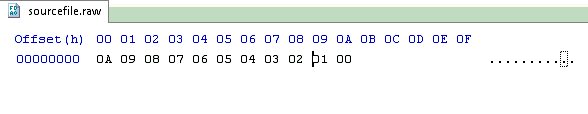
#chip 16f877a
Table TestDataSource from "sourcefile.raw"

For nn = 1 to 10
  ReadTable TestDataSource, nn, inc
  Print inc
Next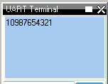
EEPROM Table Storage
#chip 16F628

TableLoc = 2
ReadTable TestDataSource, TableLoc, SomeVar

EPWrite 1, 45  'Optional write

Table TestDataSource Store Data
    12
    24
    36
    48
    60
    72
End Table
EEPROM Limitations
-
Only
BYTEvalues are supported -
WORD,INTEGER, orLONGare not compatible with EEPROM tables
Reference
See: ReadTable
Miscellaneous
About Miscellaneous things….
It is possible to combine multiple instructions on a single line, by separating them with a colon. For example, this code:
    Set PORTB.0 On
    Set PORTB.1 On
    Wait 1 sec
    Set PORTB.0 Off
    Set PORTB.0 Off
could also be written as:
    Set PORTB.0 On: Set PORTB.1 On
    Wait 1 sec
    Set PORTB.0 Off: Set PORTB.0 Off
In most cases, it will make no difference if commands share a line or not. However, special care should be taken with If commands, as this code:
    Set PORTB.0 Off
    Set PORTB.1 Off
    If Temp > 10 Then Set PORTB.0 On: Set PORTB.1 On
    Wait 1 s
Will be equivalent to this:
    Set PORTB.0 Off
    Set PORTB.1 Off
    If Temp > 10 Then
    Set PORTB.0 On
    Set PORTB.1 On
    End If
    Wait 1 s
Also, the commands used to start and end subroutines, data tables and functions must be alone on a line. For example, this is WRONG:
Sub Something: Set PORTB.0 Off: End Sub
ReadTable
About ReadTable
The ReadTable command is used to read information from lookup tables.
TableName is the name of the table that is to be read, Item is the
line of the table to read, and Output is the variable to write the
retrieved value in to.
Syntax:
ReadTable TableName, Item, Output
Command Availability:
Available on all microcontrollers.
Explanation:
Item is 1 for the first line of the table, 2 for the second, and so on.
If the Table is more than 256 elements then Item must be WORD variable.
Care must be taken to ensure that the program is not instructed to read beyond the end of the table as Zero will be returned.
The type of Output should match the type of data stored in the table.
For example, if the table contains Word values then Output should be a
Word variable. If the type does not match, GCBASIC will attempt to
convert the value.
Example:
    'Chip Settings
    #chip 16F88, 20

    'Hardware Settings
    #define LED PORTB.0
    Dir LED Out

    'Main Routine
    ReadTable TimesTwelve, 4, Temp
    Set LED Off
    If Temp = 48 Then Set LED On

    'Lookup table named "TimesTwelve"
    Table TimesTwelve
    12
    24
    36
    48
    60
    72
    84
    96
    108
    120
    132
    144
    End Table
For more help, see Lookup Tables
Scripts
About Scripts
A script is a small section of code that GCBASIC runs when it starts to compile a program. Uses include performing calculations that are required to adjust the program for different chip frequencies.
Scripts are not compiled or downloaded to the microcontroller - GCBASIC reads them, executes them, then removes them from the program and then the results calculated can be used as constants in the user program.
Inside a script, constants are treated like variables. Scripts can read the values of constants, and set them to contain new values.
Using Scripts
Scripts start with #script and end with #endscript. Inside, they can
consist of the following commands:
    If
    Assignment (=)
    Error
    Warning
    Int()
If is similar to the If command in normal GCBASIC code, except that it does not have an Else clause.
It is used to compare the values of the script constants.
The = sign is identical to that in GCBASIC programs.
The constant that is to be set goes on the left side of the = and the new value goes to the right of the =.
Error is used to display an error message.
Anything after the Error command is displayed at the end of compilation, and is saved in the error log for the program.
Warning is used to display a warning message. Anything after the Warning command is displayed at the end of compilation but warning does not halt compilation.
Int() will calculate the integer value of a calculation. Using Int() is critical to set the constant to the integer component of the calculation.
Notes:
Use Warning to display constant values when creating and debugging scripts.
Scripts have a limited syntax and limited error checking when compiling. The compiler may halt if you get something wrong.
Scripts that are incorrectly formatted may also halt the compiler or return unrelated error.
Scripts used for calculations should use the Int( expression ) where you may have a floating point numbers returned.
Scripts do use floating point for all calculations and a failure to use Int() may set the script constant and the resulting constant to 0.
Scripts may require that complex math expressions may require definition in multiple steps/line to simplify the calculation.
The returned value could be incorrect if simplification is not implemented.
Scripts can only access existing constants both user and system defined.
User defines variables are not accessible within the scope of a script.
Scripts has precendence over #define. A #define constant statements are read first, then scripts run. So, a script will always overwrite a constant that was set with #define.
Use Warning to display constants values when creating and debugging scripts.
Example Script
This script is used in the pwm.h file. It takes the values of the user defined constants PWM_Freq, PWM_Duty and system constant ChipMHz and calculates the results using the equations. These calculation are based on information from a Microchip PIC datasheet to calculate the correct values to setup Pulse Width Modulation (PWM).
    #script
        PR2Temp = INT((1/PWM_Freq)/(4*(1/(ChipMHz*1000))))
        T2PR = 1
        If PR2Temp > 255 Then
            PR2Temp = INT((1 / PWM_Freq) / (16 * (1 / (ChipMHz * 1000))))
            T2PR = 4
            If PR2Temp > 255 Then
                PR2Temp = INT(( 1 / PWM_Freq) / (64 * (1 / (ChipMHz * 1000))))
                T2PR = 16
                If PR2Temp > 255 Then
                    Error Invalid PWM Frequency value
                End If
            End If
        End If

        DutyCycle = (PWM_Duty * 10.24) * PR2Temp / 1024
        DutyCycleH = (DutyCycle AND 1020) / 4
        DutyCycleL = DutyCycle AND 3
    #endscript
During the execution of the script the calculations and assignment uses the constants in the script.
After this script has completed the constants PR2Temp, DutyCycleH and DutyCycleL are set using the constants and/or the calculations.
The constants assigned in this script, PR2Temp, DutyCycleH and DutyCycleL, are made available as constants in the user program.
Subroutines
About Subroutines
A subroutine is a small program inside of the main program. Subroutines are typically used when a task needs to be repeated several times in different parts of the main program.
There are two main uses for subroutines:
-
Keeping programs neat and easy to read
-
Reducing the size of programs by allowing common sections of code to be reused.
When the microcontroller comes to a subroutine it saves its location in the current program before jumping to the start of, or calling, the subroutine. Once it reaches the end of the subroutine it returns to the main program, and continues to run the code where it left off previously.
Normally, it is possible for subroutines to call other subroutines. There are limits to the number of times that a subroutine can call another sub, which vary from chip to chip:
| Microcontroller Family | Instruction Width | Number of subs called |
|---|---|---|
10F*, 12C5*, 12F5*, 16C5*, 16F5* |
12 |
1 |
12C*, 12F*, 16C*, 16F*, except those above |
14 |
7 |
18F*, 18C* |
16 |
31 |
These limits are due to the amount of memory on the microcontroller which saves its location before it jumps to a new subroutine. Some GCBASIC commands are subroutines, so you should always allow for 2 or 3 subroutine calls more than your program has.
On 16F chips, the program memory is divided into pages. Each page holds 2048 instructions.
If the program jumps from code on one page to code on another, the compiler has to select the new page. Having to do this makes the program bigger, so try to avoid this.
To keep jumps between pages down, GCBASIC imposes a rule that each subroutine must be entirely within one page, so that only jumps to other subroutines require the page selection.
As an example, say you have two pages of memory, each 2048 instructions (words) long.
If you have a main sub that is 1500 words, and four other subroutines each 600 words long, your total program size would be 3900 words and you might expect it to fit into the 4096 words available.
The problem though is that once the main routine takes 1500 words from page 1, nothing else will fit after it. Three of the 600 word subroutines would fit onto page 2, but that leaves one 600 word subroutine that will not fit into the 500 left on page 1 or the 200 left on page 2.
If you want to reduce the chance of this happening, the best option is to keep your subroutines smaller - move anything out of the main routine and into another one - this will resolve memory page constraints.
Atmel AVR microcontrollers have no fixed limit on how many subroutines can be called at a time, but if too many are called then some variables on the chip may be corrupted. To check if there are too many subroutines, work out the most that will be called at once, then multiply that number by 2 and create an array of that size. If an out of memory error message comes up, there are too many calls.
Another feature of subroutines is that they are able to accept parameters. These are values that are passed from the main program to the subroutine when it is called, and then passed back when the subroutine ends.
Using Subroutines
To call a subroutine is very simple - all that is needed is the name of the sub, and then a list of parameters. This code will call a subroutine named "Buzz" that has no parameters:
Buzz
If the sub has parameters, then they should be listed after the name of the subroutine. This would be the command to call a subroutine named "MoveArm" that has three parameters:
MoveArm NewX, NewY, 10
Or, you may choose to put brackets around the parameters, like so:
MoveArm (NewX, NewY, 10)
All that this does is change the appearance of the code - it doesn’t make any difference to what the code does. Decide which one meets your own personal preference, and then stick with it.
Creating subroutines
To create a subroutine is almost as simple as using one. There must be a
line at the start which has sub, and then the name of the subroutine.
Also, there needs to be a line at the end of the subroutine which reads
end sub. To create a subroutine called Buzz, this is the required
code:
    sub Buzz

    'code for the subroutine goes here

    end sub
If the subroutine has parameters, then they need to be listed after the
name. For example, to define the MoveArm sub used above, use this
code:
    sub MoveArm(ArmX, ArmY, ArmZ)

    'code for the subroutine goes here

    end sub
In the above sub, ArmX, ArmY and ArmZ are all variables. If the call
from above is used, the variables will have these values at the start of
the subroutine:
    ArmX = NewX
    ArmY = NewY
    ArmZ = 10
When the subroutine has finished running, GCBASIC will copy the values
back where possible. NewX will be assigned to ArmX, and NewY will be
assigned to ArmY. GCBASIC will not attempt to set the number 10 to ArmZ.
Controlling the direction data moves in
It is possible to instruct GCBASIC not to copy the value back after the subroutine is called. If a subroutine is defined like this:
    sub MoveArm(In ArmX, In ArmY, In ArmZ)
    'code for the subroutine goes here

    end sub
Then GCBASIC will copy the values to the subroutine, but will not copy them back.
GCBASIC can also be prevented from copying the values back, by adding
Out before the parameter name. This is used in the EEPROM reading
routines - there is no point copying a data value into the read
subroutine, so Out has been used to avoid wasting time and memory. The
EPRead routine is defined as Sub EPRead(In Address, Out Data).
Many older sections of code use #NR at the end of the line where the
parameters are specified. The #NR means "No Return", and when used has
the same effect as adding In before every parameter. Use of #NR is
not recommended, as it does not give the same level of control.
Using different data types for parameters
It is possible to use any type of variable a as parameter for a
subroutine. Just add As and then the data type to the end of the
parameter name. For example, to make all of the parameters for the
MoveArm subroutine word variables, use this code:
    sub MoveArm(ArmX As Word, ArmY As Word, ArmZ As Word)
    ...
    end sub
Optional parameters
Sometimes, the same value may be used over and over again for a parameter, except in a particular case. If this occurs, a default value may be specified for the parameter, and then a value for that parameter only needs to be given in a call if it is different to the default.
For example, suppose a subroutine to create an error beep is required. Normally it emits ! 440 Hz tone, but sometimes a different tone is required. To create the sub, this code would be use:
    Sub ErrorBeep(Optional OutTone As Word = 440)
      Tone OutTone, 100
    End Sub
Note the Optional before the parameter, and the = 440 after it.
This tells GCBASIC that if no parameter is supplied, then set the
OutTone parameter to 440.
If called using this line:
ErrorBeep
then a 440 Hz beep will be emitted. If called using this line:
ErrorBeep 1000
then the sub will produce a 1000 Hz tone.
When using several parameters, it is possible to make any number of them optional. If the optional parameter/s are at the end of the call, then no value needs to be specified. If they are at the start or in the middle, then you must insert commas to allow GCBASIC to tell where the optional parameters are.
Overloading
It is possible to have 2 subroutines with the same name, but different parameters. This is known as overloading, and GCBASIC will automatically select the most appropriate subroutine for each call.
An example of this is the Print routine in the LCD routines. There are actually several Print subroutines; for example, one has a byte parameter, one a word parameter, and one a string parameter. If this command is used:
Print 100
Then the Print (byte) subroutine will be called. However, if this command is used:
Print 30112
Then the Print (word) subroutine will be called. If there is no exact match for a particular call, GCBASIC will use the option that requires the least conversion of variable types. For example, if this command is used:
Print PORTB.0
The byte print will be used. This is because byte is the closest type to the single bit parameter.
Converters
About Converters
Converters allow GCBASIC to read files that have been created by other programs. A converter can convert these files into GCBASIC libraries or any GCBASIC instruction or a GCBASIC dataset.
A typical use case is when you have a data source file from another computer system and you want to consume the data within your GCBASIC program. The data source file could be database, graphic, reference data or music file. The converter will read these source files and convert them into a format that can be processed by GCBASIC. The conversion process is completed by external application which can be written by the developer or you can use one of the converters provided with the GCBASIC release.
The GCBASIC release includes the converter for BMP files and standard Text files.
With an appropriate Converter installed, and an associated #include to these non-GCBASIC files,
GCBASIC will detect that the file extension and hand the processing to the external converting program.
When the external converting program had complete, GCBASIC will then continue with the converted source file as a GCBASIC source file.
An example of a converter is to read an existing picture file, convert the picture file to a GCB table and then refer to the picture file table to display the picture file on a GLCD.
Conversion is achieved by including a command within the source program to transform external data.
The command used is the instruction #include followed by the data source. An example:
    'Convert ManLooking.BMP to a GCBASIC usable format.

    #include <..\converters\ManLooking.BMP>
The inclusion of the #include line within a GCBASIC program will enable the commencement of the following process:
-
GCBASIC will examine the
..\convertersfolder structure for a configuration file that will handle the file extension specified in the include statement. -
GCBASIC will examine the configuration file(s)
*.INIfor command line instructions. -
GCBASIC will at stage examine the folder structure for the source file and the target transformed file. If the source file is older than the transformed file the next step will not be executed, goto step 6.
-
GCBASIC will execute the command as specified within the configuration file to transform the source file to the target file.
The Conversion program must create the output file extension as specified in the configuration file. If the include statement as an extension of
.TXTand the configuration files states the input file extension as.TXTand the output as.GCBthe converted file must have the extension of.GCB.#include <..\converters\ManLooking.BMP>
Init file is input file as BMP and output as GCB, then the file expected is
..\converters\ManLooking.GCB -
GCBASIC will attempt to include the transformed target file (with the file extension as specified in the configuration file) within the GCBASIC program.
-
GCBASIC will resume normal processing of the GCBASIC program including the transformed target file, therefore, with normal compiling and errors handling.
For example programs see here.
More about Converters
-
The configuration file
The configuration file MUST have the extension of
.INI. No leading spaces are permitted in the configuration file. Specification of the configuration file. The file has four items:desc,in,outandexe. Where:desc : Is the description shown in GCGB in : Is the source file extension to be transformed out : Is the target transformed file extension. exe : Is the executable to be run for this specific configuration file. params : Optional, is the required parameter to be passed from the compiler. Example: params = %filename% %chipmodel% deletetarget : Optional, will always recreate the target transformed file. The default is to retain the target transformed file unless source has changed. Options are Y or N
You can have multiple configuration files within the
..\converters folder structure.GCBASIC will examine all configuration file to match the extension as specified in the
#includecommand.Example 1 :
BMP (Black and White) conversion configuration file is called
BMP2GCBasic.ini. The source extension is.bmp, the transformed file extension is.GCB, and the executable is calledBMP2GCBASIC.exe.desc = BMP file (*.bmp) in = bmp out = GCB exe = BMP2GCBASIC .exe
An example :
#include <..\converters\ManLooking.BMP>
Will be converted by the
BMP2GCBASIC .EXEto..\converters\ManLooking.GCBExample 2 :
Data file conversion configuration file is called
TXT2GCB.ini. The source extension is.TXT, the transformed file extension is.GCB, and the command line calledAWKRUN.BAT.desc = Infrared Patterns (*.txt) in = txt out = GCB exe = awkrun.bat
An example :
#include <..\converters\InfraRedPatterns.TXT>
Will be converted by the
AWKRUN.BATto..\converters\ InfraRedPatterns.GCBThe example would require a supporting batch file and a script process to complete the transformation.
-
Conversion Executable
The conversion executable may be written in any language (compiled or interpreted).
The conversion executable MUST create the converted file with the correct file extension as specified in the configuration file.
The conversion executable will be passed one parameter - the source file name. Using example #1 the conversion executable would be passed
..\converters\ManLooking.BMPThe conversion executable MUST create a GCBASIC compatible source file. Any valid commands/instruction are permitted.
-
Installation
The
INIfile, the source file and the conversion executable MUST be located in the..\converters folder. The converters folder is relative to theGCBASIC.EXEcompiler folder.
Example 3 : Converter Program
This program converts the InfraRedPatterns.TXT into InfraRedPatterns.GCB that will have a GCBASIC table called DataSource.
This example is located in the converter folder of the GCBASIC installation.
  #chip16f877a, 16
  #include <..\converters\InfraRedPatterns.TXT>

  dir portb out

  ' These must be WORDs as this could be large table.
  dim TableReadPosition, TableLen as word

  dir portb out

  ' Read the table length
  TableReadPosition = 0
  ReadTable DataSource, TableReadPosition, TableLen


  Do Forever
      For TableReadPosition = 1 to TableLen step 2
          ReadTable DataSource, TableReadPosition, TransmissionPattern
          ReadTable DataSource, TableReadPosition+1 , PulseDelay
          portb = TransmissionPattern
          wait PulseDelay ms
      next
  Loop
Example 4 : Dynamic Import
This program converts a chip specific configuration file into manifest.GCB that will have a GCBASIC functions called DataIn and DataOut.
This example is located in the converter folder of the GCBASIC installation.
    #chip 16f18326

    #include <..\converters\manifest.mcc>

    DataOut ( TX, RA0 )  'this method is created during the convert process. They do not exist withiut the converter.
    DataIn  ( Rx, RC6 )  'this method is created during the convert process. They do not exist withiut the converter.
This example would use the optional parameters of params and deletetarget in the converter configuration file as follows:
    desc = PPS file (*.PPS)
    params = %filename% %chipmodel%
    in = mcc
    out = GCB
    exe = DataHandler.exe
    deletetarget= y
Example 5 : Add build numbers and time/date details to your programs
This converter is used to expose two string variables as follows:
    GCBBuildStr
    GCBBuildTimeStr
The user code is simple. Using the #include statement specify any filename with an extension must be cnt. As follows:
#include "GCBVersionNumber.cnt"
Complete code would like this - this not optimised - this shows the use of the exposed strings.
    #include "GCBVersionNumber.cnt"

    dim versionString as string * 40
    versionString = "Max7219 build"+GCBBuildStr
    versionString = versionString + "@"+GCBBuildTimeStr
    Print versionString
This outputs the following - where #20 is the current build and the date/time is correct for build time.
    Max7219 build20@01-06-2021 08:00:21
    Commence main program
This works as the support INI file instructs the compiler to call a utility that automatically creates a build number tracker file and the supportting string functions. The utility creates a tracker file and the methods files in the same folder as your source program - so, each tracker is specific to each project. The converter requires the following files - these are included within your Installation.
    GCBVersionStamp.exe - the utility called by the converter capability.
    cnt2gcb.ini - the supporting ini file used by the compiler to handle this converter.
Command References
Analog/Digital conversion
This is the Analog/Digital conversion section of the Help file. Please refer the sub-sections for details using the contents/folder view.
Analog/Digital Conversion Overview
About Analog to Digital Conversion
The analog to digital converter (ADC or A/D) module support is implemented by GCBASIC to provide 8-bit, 10-bit and 12-bit Single channel measurement mode and Differential Channel Measurement mode.
GCBASIC configures the analog to digital converter clock source, the programmed acquisition time and justification of the response byte, word or integer (as defined in the GCBASIC method).
Normal or Single channel measurement mode
The Single channel measurement mode is the default method for reading the ADC port. The positive input is attached to suitable device (a light sensor or adjustable resistor) and the command ReadADC, ReadADC10, ReadADC12 with return a byte, word or word value respectively.
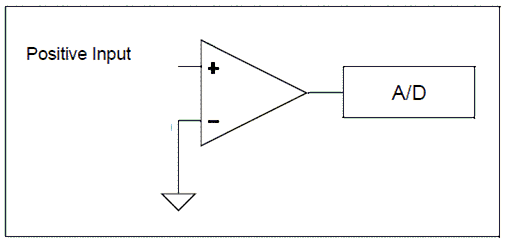
The A/D module on most microcontrollers only supports single-ended mode. Single channel mode uses a single A/D port and the returned Value represents the difference between the voltage on the analog pin and a fixed negative reference which is usually ground or Vss.
The syntax for single-ended A/D is Returned_Value = ReadAD(Port)
Example
Print ReadAD10(AN3)
Differential channel measurement mode
Some of the in the Microchip PIC family of devices also support differential analog to digital conversion. With differential conversion, the differential voltage between two channels is measured and converted to a digital value. The returned value can be either positive or negative (therefore an integer value).
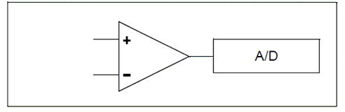
When configured to differential channel measurement mode, the positive channel is connected to the defined positive analog pin (ANx), and the negative channel is connected to the defined negative analog pin. These two pins are internally connected (within the microcontroller) to a unity gain differential amplifier and once the amplifier has completed the comparison the result is returned as an integer.
The positive channel Input is selected using the CHSx bits and the negative channel input is selected using the CHSNx bits. These bits are managed by GCBASIC. The programmer only needs to supply the correct analog pin designators in the ReadADx commands.
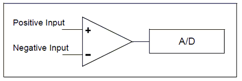
The 12-bit returned result is available on the ADRESH and ADRESL registers which is returned by the GCBASIC methods as an integer variable.
Some Microchip PIC microcontrollers have differential A/D modules and support differential Mode as well as 12-Bit A/D. With DIfferential mode the returned value can be either a positive or negative number that represents the voltage differential between the two A/D ports.
The syntax for differential A/D is ReadAD( PositiveANPort , NegativeANPort ). Note: if "negative port" is omitted readAd() will perform a single-ended read on the positive AN port.
Example
Print ReadAD12( AN3, An4 )
Using Voltage Reference
Voltage references come in many forms and offer different features across the PICs, AVR and LGTs microcontrollers. But, in the end, accuracy and stability are a voltage reference’s most important features, as the main purpose of the reference is to provide a known output voltage. Variation from this known value is an error. Therefore, it is useful to use the internal voltage reference provided within the microcontroller.
To use a voltage reference source for ADC operation sett the AD_REF_SOURCE constant to your chosen source.
The defaults to the VCC pin, and there for the constant is set by default to AD_REF_AVCC.
The voltage reference is specific to the microcontroller but the options are as follows:
| AD_REF_SOURCEConstant | Reference Voltage |
|---|---|
AD_REF_AVCC |
VCC supplied Voltage |
AD_REF_1024 |
1.024v internal reference source |
AD_REF_2048 |
2.048v internal reference source |
AD_REF_4096 |
4.096v internal reference source |
AD_REF_AREF |
Extenal voltage reference source |
AD_REF_256 |
AD_REF_256 for ATMegas |
Optimising GCBASIC Code
GCBASIC supports a wide range of A/D modules and the supporting library addresses up to 34 channels. To reduce the size of the code produced you can define which channels are specifically supported. See Optimising ADC code for more details.
For the latest Microchip PIC microcontrollers that support Differential and 12-bit A/D please refer to Microchip MAPS or the microcontrollers datasheet.
ADFormat (Deprecated - Do not use)
Syntax:
ADFormat ( Format_Left | Format_Right )
Command Availability:
Available only on Microchip PIC microcontrollers.
Explanation:
Left justified means 8 bits in the high byte, 2 in the low. Right justified means 2 in the high byte, and the remaining 8 in the low byte. It’s only supported on Microchip PIC microcontrollers.
ADOff
This command is obsolete. There should be no need to call it. GCBASIC will automatically disable the A/D converter and set all pins to digital mode when starting the program, and after every use of the ReadAD function.
It is recommended that this command be removed from all programs.
ReadAD
Syntax:
For a normal ( also called a Single Channel ) read use.
byte_variable = ReadAD( ANX )
For a Differential Channel read use the following. Where ANpX is the positive port, and ANnY is the negative port.
byte_variable = ReadAD( ANpX , ANnY )
To obtain a byte value from an AD Channel use the following to force an 8 bit AD Channel to respond with a byte value [0 to 255].
byte_variable = ReadAD( ANX , TRUE )
Command Availability:
When using ReadAD ( ANx ) the returned value is an 8 bit number [0- 255]. The byte variable assigned by the function can be a byte, word, integer or long.
When using ReadAD ( ANpX , ANnY ) the returned value is an integer, as negative values can be returned.
When using ReadAD ( ANpX , TRUE ) the returned value is an integer, but you should treat as a byte.
ReadAD is a function that can be used to read the built-in analog to digital converter that many microcontroller chips include. port should be specified as AN0, AN1, AN2, etc., up to the number of analog inputs available on the chip that is in use. Those familiar with Atmel AVR microcontrollers can also refer to the ports as ADC0, ADC1, etc. Refer to the datasheet for the microcontroller chip to find the number of ports available. (Note: it’s perfectly acceptable to use ANx on AVR, or ADCx on the microcontroller)
Other functions that are similar are ReadAD10 and ReadAD12. See the relevant Help page for the specific usage of each function.
The constant AD_Delay controls is the acquisition delay. The default value is 20 us. This can be changed by adding the following constant.
#define AD_Delay 2 10us
ADSpeed controls the source of the clock for the ADC module. It varies from one chip to another. InternalClock is a Microchip PIC microcontroller only option that will drive the ADC from an internal RC oscillator. The default value is 128.
Using ADSPEED
    'default value
    #define ADSpeed MediumSpeed


    'pre-defined constants
    #define HighSpeed 255
    #define MediumSpeed 128
    #define LowSpeed 0
AD_VREF_DELAY controls the charging time for VRef capacitor on Atmel AVR microcontrollers only. This therefore controls the charge from internal VRef. ReadAD will not be accurate for internal reference without this.
AD_Acquisition_Time_Select_bits also controls the Acquisition Time Select bits. Acquisition time is the duration that the AD charge holding capacitor remains connected to AD channel from the instant the read is commenced is set until conversions begins.
The default value of AD_Acquisition_Time_Select_bits is 0b100 or decimal 4, where all three ACQT bits will be set. To change use the following.
    'change the default value
    #define AD_Acquisition_Time_Select_bits 0b001    'this will only set ACQT bit 0, ACQT bits 1 and 2 will be cleared.
Example 1
This example reads the ADC port and writes the output to the EEPROM.
    #chip 16F819, 8

    'Set the input pin direction
    Dir PORTA.0 In

    'Loop to take readings until the EEPROM is full
    For CurrentAddress = 0 to 255

        'Take a reading and log it
        EPWrite CurrentAddress, ReadAD(AN0)

        'Wait 10 minutes before getting another reading
        Wait 10 min
    Next
Example 2
This example reads the ADC port and writes the output to the EEPROM. The output value will be in the range of [0-255].
    #chip 16F1789, 8


    'Set the input pin direction
    Dir PORTA.0 In

    'Loop to take readings until the EEPROM is full
    For CurrentAddress = 0 to 255

        'Take a reading and log it
        EPWrite CurrentAddress, ReadAD(AN0, TRUE)

        'Wait 10 minutes before getting another reading
        Wait 10 min
    Next
Example 3
This example used the diffential capabilities of ADC port and writes the output to the EEPROM. The output value will be in the range of [-255 to 255].
AN0 and AN2 are used for the diffential ADC reading.
    #chip 16F1789, 8


    'Set the input pin direction
    Dir PORTA.0 In
    Dir PORTA.2 In

    'Loop to take readings until the EEPROM is full
    For CurrentAddress = 0 to 255

        'Take a reading and log it
        EPWrite CurrentAddress, ReadAD( AN0, AN2 )

        'Wait 10 minutes before getting another reading
        Wait 10 min
    Next
ReadAD10
Syntax:
For a normal ( also called a Single Channel ) read use.
word_variable = ReadAD10( ANX )
For a Differential Channel read use the following. Where ANpX is the positive port, and ANnY is the negative port.
integer_variable = ReadAD10( ANpX , ANnY )
To obtain a 10-bit value from an AD Channel use the following to force a 10 bit AD Channel to respond with the correct value, in terms of the range [0 to 1023]
integer_variable = ReadAD10( ANX , TRUE )
Command Availability:
ReadAD10 is a function that can be used to read the built-in analog to digital converter that many microcontroller chips include. The port should be specified as AN0, AN1, AN2, etc., up to the number of analog inputs available on the chip that is in use. Those familiar with Atmel AVR microcontrollers can also refer to the ports as ADC0, ADC1, etc. Refer to the datasheet for the microcontroller chip to find the number of ports available. (Note: it’s perfectly acceptable to use ANx on AVR, or ADCx on the microcontroller.)
When using ReadAD10 ( ANX ) the returned value is the full range of the ADC module. Therefore, the method will return an 8 bit value [0-255], or an 10 bit value [0-1023] or an 12 bit value [0-4095]. This is dependent on the microcontrollers capabilities. For a 10 bit value [0-1023] always to be returned use user_variable = ReadAD10( ANX , TRUE ). The user variable can be a byte, word, integer or long but typically a word is recommnended.
When using ReadAD10 ( ANpX , ANnY ), for differential ADC reading, the returned value is an integer as negative values will be returned.
When using ReadAD10 ( ANpX , TRUE ), to force a 10 bit ADC reading, the returned value is an integer.
Other functions that are similar are ReadAD and ReadAD12. See the relevant Help page for the specific usage of each function.
AD_Delay controls is the acquisition delay. The default value is 20 us. This can be changed to a longer acquisition delay by adding the following constant.
#define AD_Delay 4 10us
ADSpeed( controls the source of the clock for the ADC module. It varies from one chip to another. InternalClock is a microcontroller only option that will drive the ADC from an internal RC oscillator. The default value is 128.
    'default value
    #define ADSpeed MediumSpeed


    'pre-defined constants
    #define HighSpeed 255
    #define MediumSpeed 128
    #define LowSpeed 0
AD_Acquisition_Time_Select_bits also controls the Acquisition Time Select bits. Acquisition time is the duration that the AD charge holding capacitor remains connected to AD channel from the instant the read is commenced is set until conversions begins.
The default value of AD_Acquisition_Time_Select_bits is 0b100 or decimal 4, where all three ACQT bits will be set. To change use the following.
    'change the default value
    #define AD_Acquisition_Time_Select_bits 0b001    'this will only set ACQT bit 0, ACQT bits 1 and 2 will be cleared.
Example 1 - Read 10-bit ADC
    #chip 16F819, 8

    'Set the input pin direction
    Dir PORTA.0 In


    'Print 255 reading
    For CurrentAddress = 0 to 255

        'Take a reading and show it
        Print str(ReadAD10(AN0))

        'Wait 10 minutes before getting another reading
        Wait 10 min
    Next
Example 2 - Reading Reference Voltages:
When selecting the reference source for ADC on ATmega328 GCBASIC will overwrite anything that you put into te ADMUX register - but this option allow you change the ADC reference source on Atmel AVR microcontrollers. You can set the AD_REF_SOURCE constant to whatever you want to use. It defaults to the VCC pin, as example you can set the Atmel AVR to use the 1.1V reference with this: #define AD_REF_SOURCE AD_REF_256 where 256 refers to the 2.56V reference on some older AVRs, but the same code will select the 1.1V reference on an ATmega328p
    ' Dynamically switching reference.
    #define AD_REF_SOURCE ADRefSource
    #define AD_VREF_DELAY 5 ms
    AdRefSource = AD_REF_AVCC
    HSerPrint ReadAD10(AN1)
    HSerPrint ", "
    AdRefSource = AD_REF_256
    HSerPrint ReadAD10(AN1)
The example above sets the AD_REF_SOURCE to a variable, and then changes the value of the variable to select the source. With this approach, we also need to allow time to charge the reference capacitor to the correct voltage.
Example 3 - Read 10-bit ADC forcing a 10-bit value to be returned
    #chip 16F1789, 8

    'Set the input pin direction
    Dir PORTA.0 In


    'Print 255 reading
    For CurrentAddress = 0 to 255

        'Take a reading and show it
        Print str(ReadAD10(AN0), TRUE)

        'Wait 10 minutes before getting another reading
        Wait 10 min
    Next
Example 4
This example used the diffential capabilities of ADC port and writes the output to the EEPROM. The output value will be in the range of [-1023 to 1023].
AN0 and AN2 are used for the diffential ADC reading.
    #chip 16F1789, 8

    'USART settings
    #define USART_BAUD_RATE 9600  'Initializes USART port with 9600 baud
    #define USART_TX_BLOCKING ' wait for tx register to be empty
    wait 100 ms

    'Set the input pin direction
    Dir PORTA.0 In
    Dir PORTA.2 In

    'Loop to take readings until the EEPROM is full
    For CurrentAddress = 0 to 255

        'Take a reading and log it
        HSerPrint ReadAD10( AN0, AN2 )
        HserPrintCRLF
        'Wait 10 minutes before getting another reading
        Wait 10 min

    Next
ReadAD12
Syntax:
For a normal ( also called a Single Channel ) read use.
user_variable = ReadAD12( ANX )
For a Differential Channel read use the following. Where ANpX is the positive port, and ANnY is the negative port.
user_variable = ReadAD12( ANpX , ANnY )
To obtain a 12-bit value from an AD Channel use the following to force a 12 bit AD Channel to respond with the correct value, in terms of the range of [0 to 4095]
user_variable = ReadAD12( ANX , TRUE )
Command Availability:
When using ReadAD12 ( ANX ) the returned value is an 12 bit number [0-4095]. The user variable can be a word, integer or long.
When using ReadAD12 ( ANpX , ANnY ) the returned value is an integer as negative values can be returned.
ReadAD12 is a function that can be used to read the built-in analog to digital converter that many microcontroller chips include. Port should be specified as AN0, AN1, AN2, etc., up to the number of analog inputs available on the chip that is in use. Those familiar with Atmel AVR microcontrollers can also refer to the ports as ADC0, ADC1, etc. Refer to the datasheet for the microcontroller chip to find the number of ports available. (Note: it’s perfectly acceptable to use ANx on AVR, or ADCx on the microcontroller.)
Other functions that are similar are ReadAD and ReadAD10. See the relevant Help page for the specific usage of each function.
AD_Delay controls is the acquisition delay. The default value is 20 us. This can be changed to a longer acquisition delay by adding the following constant.
#define AD_Delay 4 10us
ADSpeed( controls the source of the clock for the ADC module. It varies from one microcontroller to another. InternalClock is a Microchip PIC microcontroller only option that will drive the ADC from an internal RC oscillator. The default value is 128.
    'default value
    #define ADSpeed MediumSpeed


    'pre-defined constants
    #define HighSpeed 255
    #define MediumSpeed 128
    #define LowSpeed 0
AD_Acquisition_Time_Select_bits also controls the Acquisition Time Select bits. Acquisition time is the duration that the AD charge holding capacitor remains connected to AD channel from the instant the read is commenced is set until conversions begins.
The default value of AD_Acquisition_Time_Select_bits is 0b100 or decimal 4, where all three ACQT bits will be set. To change use the following.
    'change the default value
    #define AD_Acquisition_Time_Select_bits 0b001    'this will only set ACQT bit 0, ACQT bits 1 and 2 will be cleared.
Example 1 - Read 12-bit ADC
    #chip 16F1788, 8

    'Set the input pin direction
    Dir PORTA.0 In


    'Print 255 readings
    For CurrentAddress = 0 to 255

        'Take a reading and show it
        Print str(ReadAD12(AN0))

        'Wait 10 minutes before getting another reading
        Wait 10 min
    Next
Example 2 - Force a 12-bit value to be returned
    #chip 16F1788, 8


    'Set the input pin direction
    Dir PORTA.0 In


    'Print 255 readings
    For CurrentAddress = 0 to 255

        'Take a reading and show it
        Print str(ReadAD12(AN0), TRUE)

        'Wait 10 minutes before getting another reading
        Wait 10 min
    Next
Example 3
This example used the diffential capabilities of ADC port and writes the output to the EEPROM. The output value will be in the range of [-4095 to 4095].
AN0 and AN2 are used for the diffential ADC reading.
    #chip 16F1789, 8

    'USART settings
    #define USART_BAUD_RATE 9600  'Initializes USART port with 9600 baud
    #define USART_TX_BLOCKING ' wait for tx register to be empty
    wait 100 ms

    'Set the input pin direction
    Dir PORTA.0 In
    Dir PORTA.2 In

    'Loop to take readings until the EEPROM is full
    For CurrentAddress = 0 to 255

        'Take a reading and log it
        HSerPrint ReadAD12( AN0, AN2 )
        HserPrintCRLF
        'Wait 10 minutes before getting another reading
        Wait 10 min

    Next
Analog/Digital Conversion Code Optimisation
About Analog/Digital Conversion Code Optimisation
The analog to digital converter (ADC or A/D) module support is implemented by GCBASIC to provide 8-bit, 10-bit and 12-bit Single channel measurement mode and Differential Channel Measurement with support up to 34 channels. For compatibility all channels are supported.
There are two methods to optimise the code.
-
To mimise the code, use the contstants to disable support for a specfic channels
-
To adapt the ADC configuration by inserting specfic commands to set registers or register bits.
1. Minimise the code
The example below would disable support for ADC port 0 (AD0).
#define USE_AD0 FALSE
The following tables show the #defines that can be used to reduce the code size - these are the defines for the standard microcontrollers. For 16f1688x and similar microcontrollers please see the second table.
| Channel | Optimisation Value | Default Value |
|---|---|---|
|
|
|
|
|
|
|
|
|
|
|
|
|
|
|
|
|
|
|
|
|
|
|
|
|
|
|
|
|
|
|
|
|
|
|
|
|
|
|
|
|
|
|
|
|
|
|
|
|
|
|
|
|
|
|
|
|
|
|
|
|
|
|
|
|
|
|
|
|
|
|
|
|
|
|
|
|
|
|
|
|
|
|
|
|
|
|
|
|
|
|
|
|
|
|
|
|
|
|
|
|
|
|
|
|
For 16f1688x devices see the table below.
| Channel | Optimisation Value | Default Value |
|---|---|---|
|
|
|
|
|
|
|
|
|
|
|
|
|
|
|
|
|
|
|
|
|
|
|
|
|
|
|
|
|
|
|
|
|
|
|
|
|
|
|
|
|
|
|
|
|
|
|
|
|
|
|
|
|
|
|
|
|
|
|
|
|
|
|
|
|
|
|
|
|
|
|
|
|
|
|
|
|
|
|
|
|
This is a example - disables every channel except the specified channel by defining every channel except USE_AD0 as FALSE.
This will save 146 bytes of program memory.
    #chip 16F1939

    'USART settings
    #define USART_BAUD_RATE 9600
    #define USART_TX_BLOCKING

    'Set the input pin direction
    Dir PORTA.0 In

    'Print 255 reading
    For CurrentAddress = 0 to 255

        'Take a reading and show it
        HSerPrint str(ReadAD10(AN0))

        'Wait 10 minutes before getting another reading
        Wait 10 min
    Next

    #define USE_AD0 TRUE
    #define USE_AD1 FALSE
    #define USE_AD2 FALSE
    #define USE_AD2 FALSE
    #define USE_AD3 FALSE
    #define USE_AD4 FALSE
    #define USE_AD5 FALSE
    #define USE_AD6 FALSE
    #define USE_AD7 FALSE
    #define USE_AD8 FALSE
    #define USE_AD9 FALSE
    #define USE_AD10 FALSE
    #define USE_AD11 FALSE
    #define USE_AD12 FALSE
    #define USE_AD13 FALSE
    #define USE_AD14 FALSE
    #define USE_AD15 FALSE
    #define USE_AD16 FALSE
    #define USE_AD17 FALSE
    #define USE_AD18 FALSE
    #define USE_AD19 FALSE
    #define USE_AD20 FALSE
    #define USE_AD21 FALSE
    #define USE_AD22 FALSE
    #define USE_AD23 FALSE
    #define USE_AD24 FALSE
    #define USE_AD25 FALSE
    #define USE_AD26 FALSE
    #define USE_AD27 FALSE
    #define USE_AD28 FALSE
    #define USE_AD29 FALSE
    #define USE_AD30 FALSE
    #define USE_AD31 FALSE
    #define USE_AD32 FALSE
    #define USE_AD33 FALSE
    #define USE_AD34 FALSE
For 16f18855 family of microcontrollers this is a example. This will save 149 bytes of program memory.
    '''  PIC: 16F18855
    '''  Compiler: GCB
    '''  IDE: GCode
    '''
    '''  Board: Xpress Evaluation Board
    '''  Date: 13.3.2021
    '''


        'Chip Settings.
        #CHIP 16F18855,32
        #CONFIG MCLRE_ON
        #OPTION EXPLICIT

        '' -------------------LATA-----------------
        '' Bit#:  -7---6---5---4---3---2---1---0---
        '' LED:   ---------------|D5 |D4 |D3 |D1 |-
        ''-----------------------------------------
        ''

        #define USART_BAUD_RATE 19200
        #define USART_TX_BLOCKING

        #define LEDD2 PORTA.0
        #define LEDD3 PORTA.1
        #define LEDD4 PORTA.2
        #define LEDD5 PORTA.3
        Dir     LEDD2 OUT
        Dir     LEDD3 OUT
        Dir     LEDD4 OUT
        Dir     LEDD5 OUT

        #define SWITCH_DOWN         0
        #define SWITCH_UP           1

        #define SWITCH              PORTA.5


        'Setup an Interrupt event when porta.5 goes negative.
        IOCAN5 = 1
        On Interrupt PORTABChange  Call InterruptHandler

        do

         'Read the value from the EEPROM from register Zero in the EEPROM
          EPRead ( 0, OutValue )

          'Leave the Top Bytes alone and set the lower four bits
          PortA = ( PortA & 0XF0 ) OR ( OutValue / 16 )
          Sleep

        loop


    sub InterruptHandler

        if IOCAF5 = 1 then                         'S2 was just pressed
            IOCAN5 = 0                             'Prevent the event from reentering the InterruptHandler routine
            IOCAF5 = 0                             'We must clear the flag in software

            wait 5 ms                              'debounce by waiting and seeing if still held down
            if ( SWITCH = SWITCH_DOWN ) then
                'Read the ADC
                adc_value = readad ( AN4 )
                'Write the value to register Zero in the EEPROM
                EPWrite ( 0, adc_value )
            end if
            IOCAN5 = 1                              'ReEnable the InterruptHandler routine

        end if

    end sub

    #define USE_ADA0 FALSE
    #define USE_ADA1 FALSE
    #define USE_ADA2 FALSE
    #define USE_ADA3 FALSE
    #define USE_ADA4 TRUE
    #define USE_ADA5 FALSE
    #define USE_ADA6 FALSE
    #define USE_ADA7 FALSE
    #define USE_ADB0 FALSE
    #define USE_ADB1 FALSE
    #define USE_ADB2 FALSE
    #define USE_ADB3 FALSE
    #define USE_ADB4 FALSE
    #define USE_ADB5 FALSE
    #define USE_ADB6 FALSE
    #define USE_ADB7 FALSE
    #define USE_ADC0 FALSE
    #define USE_ADC1 FALSE
    #define USE_ADC2 FALSE
    #define USE_ADC3 FALSE
    #define USE_ADC4 FALSE
    #define USE_ADC5 FALSE
    #define USE_ADC6 FALSE
    #define USE_ADC7 FALSE
    #define USE_ADD0 FALSE
    #define USE_ADD1 FALSE
    #define USE_ADD2 FALSE
    #define USE_ADD3 FALSE
    #define USE_ADD4 FALSE
    #define USE_ADD5 FALSE
    #define USE_ADD6 FALSE
    #define USE_ADD7 FALSE
    #define USE_ADE0 FALSE
    #define USE_ADE1 FALSE
    #define USE_ADE2 FALSE
2. Adapt the ADC configuration
Example 1:
The following example will set the specific register bits. The instruction will be added to the compiled code.
#define ADReadPreReadCommand ADCON.2=0:ANSELA.0=1
The constant ADReadPreReadCommand can be used to adapt the ADC methods. The constant can enable registers or register bit(s) that are required to managed for a specfic solution.
In the example above the following ASM will be added to your code. This WILL be added just before the ADC is enabled and the setting of the acquisition delay.
  ;ADReadPreReadCommand
  banksel ADCON
  bcf ADCON,2
  banksel ANSELA
  bsf ANSELA,0
Example 2:
The following example can be used to change the ADMUX to support a sensor on ADC4.
This supports reading the internal temperature sensor on the ATTINY85. This method will work on other similar chips. Please refer the chip specific datasheet.
This will call a macro to change the ADMUX to read the ATTINY85 internal temperature sensor, set the reference voltage to 1v1 and then wait 100 ms.
#define ADREADPREREADCOMMAND ATTINY85ReadInternalTemperatureSensor
Macro ATTINY85ReadInternalTemperatureSensor
/*
17.12 of the datasheet
The temperature measurement is based on an on-chip temperature sensor that is coupled to a single ended ADC4
channel. Selecting the ADC4 channel by writing the MUX[3:0] bits in ADMUX register to 1111 enables the temperature sensor. The internal 1.1V reference must also be selected for the ADC reference source in the
temperature sensor measurement. When the temperature sensor is enabled, the ADC converter can be used in
single conversion mode to measure the voltage over the temperature sensor.
The measured voltage has a linear relationship to the temperature as described in Table 17-2 The sensitivity is
approximately 1 LSB / ?C and the accuracy depends on the method of user calibration. Typically, the measurement
accuracy after a single temperature calibration is ±10?C, assuming calibration at room temperature. Better
accuracies are achieved by using two temperature points for calibration.
*/
IF ADReadPort=4 then
ADMUX = ( ADMUX and 0X20 ) or 0X8F
wait 100 ms
End if
End Macro
This will generate the following ASM.
    ;ADREADPREREADCOMMAND  'adds user code below
      lds SysCalcTempA,ADREADPORT
      cpi SysCalcTempA,4
      brne  ENDIF2
      ldi SysTemp2,32
      in  SysTemp3,ADMUX
      and SysTemp3,SysTemp2
      mov SysTemp1,SysTemp3
      ldi SysTemp2,143
      or  SysTemp1,SysTemp2
      out ADMUX,SysTemp1
      ldi SysWaitTempMS,100
      ldi SysWaitTempMS_H,0
      rcall Delay_MS
    ENDIF2:
Bitwise
This is the Bitwise section of the Help file. Please refer the sub-sections for details using the contents/folder view.
Bitwise Operations Overview
About Bitwise Operations
GCBASIC (as with most other microcontroller programming languages) supports bitwise operations.
Bitwise operations are performed on one or more bit patterns at the level of their individual bits.
GCBASIC supports the following methods.
| Method | Meaning |
|---|---|
Set |
Assigns a Bit value of On or Off |
SetWith |
Evaluates an expression and assigns the result |
FnLSL |
Performs a Bitwise LEFT shift |
FnLSR |
Performs a Bitwise RIGHT shift |
Rotate |
Performs a rotation of a variable of one bit in a specified direction |
FnLSL
Syntax:
BitsOut = FnLSL(BitsIn, NumBits)
Command Availability:
Available on all microcontrollers.
Explanation:
FnLSL (Logical Shift Left) will perform a Bitwise left shift.
FnLSL will return BitsIn shifted NumBits to the left, it is equivalent to the 'C' operation:
BitsOut = BitsIn << NumBits
Each left shift is the equivalent of multiplying BitsIn by 2. BitsIn and NumBits may be may be a variable and of type: Bit, Byte, Word, Long, Constant or another Function. Zeros are shifted in from the right, Bits that are shifted out are lost.
It is useful for mathematical and logical operations, as well as creating serial data streams or manipulating I/O ports.
Example:
    ' This program will shift the LEDs on the Microchip PIC Low Pin
    ' Count Demo Board from Right to Left, that is DS1(RC0) to
    ' DS4(RC3) and repeat

    #chip    16f690        ' declare the target Device

    #define  LEDPORT PORTC ' LEDs on pins 16, 15, 14 and 7

    Dim LEDMask as Byte    ' Pattern to be displayed
    LEDMask = 0b0001       ' Initialise the Patten
    Dir LEDPORT Out        ' Enable the LED Port.

    Do
        LEDMask = FnLSL(LEDMask, 1) & 0x0F    ' Mask the lower 4 bits
        if LEDPORT.3 then LEDMask.0 = 1       ' Restart the sequence
        LEDPORT = LEDMask                     ' Display the Pattern
        wait 500 ms
    Loop
    End
See Also Bitwise Operations Overview and Conditions
FnLSR
Syntax:
BitsOut = FnLSR(BitsIn, NumBits)
Command Availability:
Available on all microcontrollers.
Explanation:
FnLSR (Logical Shift Right) will perform a Bitwise right shift. FnLSR will return BitsIn shifted NumBits to the right, it is equivalent to the 'C' operation:
BitsOut = BitsIn >> NumBits
Each right shift is the equivalent of dividing BitsIn by 2.
BitsIn and NumBits may be may be a variable and of type: Bit, Byte, Word, Long, Constant or another Function.
Zeros are shifted in from the left, Bits that are shifted out are lost.
It is useful for mathematical and logical operations, as well as creating serial data streams or manipulating I/O ports.
Example:
    ' This program will shift the LEDs on the Microchip PIC Low Pin Count Demo Board
    ' from Right to Left, that is DS4(RC3) to DS1(RC0) and repeat.

    #chip    16f690        ' declare the target Device

    #define  LEDPORT PORTC ' LEDs on pins 16, 15, 14 and 7

    Dim LEDMask as Byte    ' Pattern to be displayed
    LEDMask = 0b1000       ' Initialise the Patten
    Dir LEDPORT Out        ' Enable the LED Port.

    Do
      LEDPORT = LEDMask    ' Display the Pattern
      wait 500 ms
      LEDMask = FnLSR(LEDMask, 1) & 0x0F ' Mask the lower 4 bits
      if LEDPORT.0 then LEDMask.3 = 1    ' Restart the sequence
    Loop
    End
See Also Bitwise Operations Overview and Conditions
SetWith
Syntax:
SetWith(TargetBit, Source)
Command Availability:
Available on all microcontrollers.
Explanation:
SetWith is an extended version of SET, it allows a Bit Field to be set or cleared by evaluating the content of Source. SetWith should always be used when TargetBit is an I/O Bit and Source is a Function, in order to avoid the possibility of I/O jitter.
Source may be a variable and of type: Bit, Byte, Word or Long, a Constant, an expression or a Function.
It will SET TargetBit to 1 if Source evaluates to anything other than zero. TargetBit will always be a 1 or a 0 regardless of the variable type of TargetBit.
Example:
    ' This program will reflect the state of SW1(RA3) on LED DS1(RC0) of the Microchip
    ' Low Pin Count Demo Board. Notice that because SW1 is normally High the state has to
    ' be inverted to turn on the LED (DS1) when SW1 is pressed.

    #chip   16f690    ' declare the target Device

    #Define SW1 PORTA.3
    #Define DS1 PORTC.0

    DIR DS1 Out
    DIR SW1 In

    Do
      ' set the Bit DS1 to equal the Bit SW1
      SetWith( DS1, !SW1 )
    Loop
    END
See Also Bitwise Operations Overview and Conditions
Memory
This is the Memory section of the Help file. Please refer the sub-sections for details using the contents/folder view.
MCU EEPROM ( DFM )
This is the EEPROM ( PFM ) section of the Help file. Please refer the sub-sections for details using the contents/folder view.
EPRead
Syntax:
EPRead location, store
Command Availability:
Available on all Microchip PIC and Atmel AVR microcontrollers with EEPROM data memory.
Explanation:
EPRead is used to read information from the EEPROM data storage that many microcontroller chips are equipped with.
location represents the location to read data from, and varies from one chip to another.
store is the variable in which to store the data after it has been read from EEPROM.
Note Do not exceed the location ( also known as the EEProm address ) of the physical EEProm. If the EEProm size is 256 ensure location is in the range of 0 to 255; If the EEProm size is 512 ensure location is in the range of 0 to 511 and use a Word variable as the location parameter. Example:
Example:
    'Program to turn a light on and off
    'Will remember the last status

    #chip tiny2313, 1
    #define Button PORTB.0
    #define Light PORTB.1

    Dir Button In
    Dir Light Out

    'Load saved status
    EPRead 0, LightStatus

    If LightStatus = 0 Then
      Set Light Off
    Else
      Set Light On
    End If

    Do
      'Wait for the button to be pressed
      Wait While Button = On
      Wait While Button = Off
      'Toggle value, record
      LightStatus = !LightStatus
      EPWrite 0, LightStatus

      'Update light
      If LightStatus = 0 Then
        Set Light Off
      Else
        Set Light On
      End If
    Loop
For more help, see EPWrite
EPWrite
Syntax:
EPWrite location, data
Command Availability:
Available on all Microchip PIC and Atmel AVR microcontrollers with EEPROM data memory.
Explanation:
EPWrite is used to write information to the EEPROM data storage, so that
it can be accessed later by a programmer on the PC, or by the EPRead
command. location represents the location to write data to, and the location varies
from one chip to another. data is the data that is to be written to the
EEPROM, and can be a value or a variable.
|
Note
|
Do not exceed the location ( also known as the EEProm address ) of the physical EEProm. If the EEProm size is 256 ensure location is in the range of 0 to 255; If the EEProm size is 512 ensure location is in the range of 0 to 511 and use a Word variable as the location parameter. |
Example:
    #chip 16F819, 8

    'Set the input pin direction
    Dir PORTA.0 In

    'Loop to take readings until the EEPROM is full
    For CurrentAddress = 0 to 255

    'Take a reading and log it
    EPWrite CurrentAddress, ReadAD(AN0)

    'Wait 10 minutes before getting another reading
    Wait 10 min

    Next
For more help, see EPRead,Creating EEProm data from a Lookup Table
Dataset for EEPROM
Syntax:
        EEPROM DataSetName [[,]address]
            // multiples values, strings etc.
            0,1,2,3
        END EEPROM
Command Availability:
Available on all PIC microcontrollers with EEPROM memory. AVR support required use of AVR-ASM assembler. GCASM does not support AVR EEPROM operations.
Explanation:
The EEPROM construct creates an EEPROM dataset for use with the specific microcontroller. An EEPROM dataset is a list of values that are stored in the EEPROM memory of the microcontroller, which then can be accessed using the EPREAD() command or other EEPROM read operations.
The advantage of an EEPROM dataset is that they are memory efficient being loaded directly into the EEPROM during programming operations.
EEPROM datasets are defined as follows:
-
Byte values,
-
EEPROM addresses and EEPROM datasets CANNOT overlap,
-
EEPROM addresses must not overlap TABLE data,
-
TABLE data has precedence from address 0x00 until the the end of TABLE all data,
-
Strings must be expressed as ASCII byte value(s),
-
Multiple elements on a single line separated by commas,
-
Constants and calculations within the single line dataset entries are permitted,
-
Decimal values are NOT supported,
-
Access is via EPRread(), not supported by READTABLE().
-
18F devices must use even address for EEPROM location, and, 18F will pad (with 0x00) datasets to even number length. This is MPASM constraint and therefore the compiler and assembler will isssue specific error messages for odd EEPROM locations.
Defining EEPROM datasets
Single data values
A single value on each line with in the dataset. The example dataset, shown below, has the data on different line in within the set.
Simple example: This creates an EEPROM dataset at the first EEPROM location, then, the values of 12, 24, … 72 are the consecutive values.
        EEPROM EEDataSet
            12
            24
            36
            48
            60
            72
        End EEPROM
Multiple data values of the same line
The following example creates the EEPROM dataset at EEPROM offset address of 0x10.
Multiple elements on a single line separated by commas. The example dataset, shown below, has the data separated by , and on different line in within the dataset.
        EEPROM EEDataSource  0x10
            12,  24, 36
            48,  60, 72
        End EEPROM
Data values as constants, and, with data transformation
Constants and calculations within the single line. The example dataset, shown below, uses a defined constant to multiple the data with the dataset.
        #define calculation_constant 2

        EEPROM EEDataSource  0x20
        1 * calculation_constant
        2 * calculation_constant
        3 * calculation_constant
        8 * calculation_constant
        4 * calculation_constant
        5 * calculation_constant
        End EEPROM
Data values as Strings
Strings can be defined. Strings are delimited by double quotes. The following examples show the methods.
Any ASCII characters between any two " " (double quotes) will be converted to dataset data. Also see ASCII escape codes.
A source string can be one string per line or comma separated strings, therefore, on the same line.
Example:
    EEPROM Test_1
     "ABCDEFGHIJ"
    End EEPROM
ASCII Escape code
Accepted escape strings are shown in the dataset below.
| Escape sequence | Meaning |
|---|---|
\a |
beep |
\b |
backspace |
\f |
formfeed |
\l or \n |
newline |
\r |
carriage return |
\t |
tab |
\0 |
Null value, equates to ASCII 0. Same as \&000 |
\&nnn |
ascii char in decimal |
\\ |
backslash |
\" |
double quote |
\' |
single quote |
Complete working example program
This example creates several EEPROM datasets. The example also create a lookup table. The EEPROM dataset are addressed with the additional parameter to ensure there is no EEPROM dataset overlap.
        #chip 16F886
        #option explicit

        #DEFINE USART_BAUD_RATE 9600
        #DEFINE USART_TX_BLOCKING
        #DEFINE USART_DELAY OFF

        Dim EEdataaddress, myvar as Byte
        EEdataaddress = 2

        Readtable TwoBytes,EEdataaddress,myVar
        HSerPrint myVar


        // *********************** EXAMPLE EE DATA ************************
        // * THIS IS ONLY ACCESSIBLE VIA EPREAD or other EE read functions.
        /*
        Usage:      EEProm EEPromBlockName [[,] OffSet Address ]
                    OffSet address defaults to 0x00 if not stated.

                    Addresses and datasets CANNOT overlap.
                    Addresses must not overlap TABLE data.
                    TABLE data has precendence from address 0x00 until the the end of TABLE data
        */


        EEProm EEDataSet1 0x10    // Locate EE Data at address
        3,2,1
        End EEProm

        EEProm VersionData 0x20   // Locate EE Data at address
        "    PWM2Laser   "
        "  Fabrice ENGEL "
        "   Version 1.4  "
        "  November 2023 "
        End EEProm

        EEProm EEDataSet2 0x0D    // Locate EE Data at address
        1,2,3
        End EEProm

        EEProm EEDataSet 0X04     // Locate EE Data at address
        1,2,3
        End EEProm

        // **********************  EXAMPLE TABLE DATA BEING LOADED INTO EE BY THE COMIPILER
        // *                       THIS IS ONLY ACCESSIBLE VIA READTABLE

        Table TwoBytes STORE data // EE Data Address Allocated by compiler
            0X55,0XAA,0X55
        End Table
For more help, see EPRead, Creating EEProm data from a Lookup Table
HEFM ( PFM )
This is the HEFM ( PFM ) section of the Help file. Please refer the sub-sections for details using the contents/folder view.
HEFM Overview
Introduction:
Some enhanced mid-range Microchip PIC devices support High-Endurance Flash (HEF) memory. These devices lack the data EEPROM found on other devices.
Instead, they implement an equivalent amount of special flash memory, called HEF memory, that can provide an endurance comparable to that of a traditional data EEPROM.
HEF memory can be erased and written 100,000 times.
HEF memory appears in the regular program memory space and can be used for any purpose, like regular flash program memory.
As with all flash memory, data must be erased before it can be written and writing this memory will stall the device.
Methods to read, write and erase the HEF memory are included in GCBASIC and they are described in this introduction. Also see Microchip application note AN1673, Using the PIC16F1XXX High-Endurance Flash (HEF) Block.
The hefsaf.h library supports HEF operations for GCBASIC.
Note: By default, GCBASIC will use HEF memory for regular executable code unless it is told otherwise.
If you wish to store data here, you should reserve the HEF memory by using the compiler option, as shown below to reserve 128 words of HEF memory:
#option ReserveHighProg 128
HEF memory is a block of memory locations found at the top of the flash program memory.
Each memory location can be used to hold a 8-bit byte value.
To further explain, the PIC 16F Enhanced Midrange Sevices memory architecture is 14-bits wide. Therefore, for a single 14-bit memory location it is only practical to store an 8-bit byte value, and two 14-bit memory locations to hold one 16-bit word value.
This is because the memory architecture only allows the use of the the lower 8-bits of each 14-bit flash memory location for HEF usage
The main difference between HEF memory and EEPROM is that EEPROM allows byte-by-byte erase whereas the HEF memory does not.
With HEF memory, data must be erased before a write and the erase can only be performed in blocks of memory.
The blocks, also called rows, are a fixed size associated with the specific device.
GCBASIC handles the erase operation automatically.
When a write operation is used by a user the GCBASIC library reads to a cache, updates the cache, erase the block and finally write the caches.
The complexity of using HEF memory is reduced with the automatically handling of these operations.
The hefsaf.h library provides a set of methods to support the use of HEF memory.
Method |
Parameters |
Usage |
|
a subroutine with the parameters: location, byte value |
HEFWrite ( location, byte_variable ) |
|
a subroutine with the parameters: location, word_value |
HEFWriteWord ( location, word_variable ) |
|
a function with the parameters: location returns a byte value |
byte_variable = HEFRead ( location ) |
|
a subroutine with the paramers: location, byte_value |
HEFRead ( location , out_byte_variable ) |
|
a function with the parameters: location returns a word value |
word_variable = HEFRead ( location ) |
|
a subroutine with the parameters: location, word_value |
HEFRead ( location , out_word_variable ) |
|
a subroutine with the parameters: block_number |
HEFEraseBlock ( 0 )
|
|
a subroutine with the parameters: block_number, buffer() [, HEF_ROWSIZE_BYTES ] |
HEFWriteBlock( 0, myMemoryBuffer ) 'where myMemoryBuffer is an Array or a String
|
|
a subroutine with the parameters: block_number, buffer() [, HEF_ROWSIZE_BYTES ] |
HEFReadBlock( 0, myMemoryBuffer ) 'where myMemoryBuffer is an Array or a String.
|
The library also defines a set constants that are specific to the device.
These may be useful in the user program.
These constants are used by the library.
A user may use these public constants.
Constant |
Type |
Usage |
|
Byte |
Size of an HEFM block in words |
|
Word or a Byte |
ChipHEFMemWords parameter from the device .dat file |
|
Word |
Starting address of HEFM |
|
Byte |
Number of blocks of HEFM |
|
Word |
Device specific constant for the total flash size |
|
Word |
Device specific constant for the number of HEFM words available |
|
Word |
Device specific constant for the number of HEFM in an erase row |
Warning
Whenever you update the hex file of your Microchip PIC micro-controller with your programmer you MAY erase the data that are stored in HEF memory.
If you want to avoid that you will have to flash your Microchip PIC micro-controller with software that allows memory exclusion when flashing.
This is the case with Microchip PIC MPLAB IPE (Go to Advanced Mode/Enter password/Select Memory/Tick “Preserve Flash on Program”/
Enter Start and End address of your HEFM). Or, simply use the PICkitPlus suite of software to preserve HEF memory during programming.
See also
HEFRead,
HEFReadWord,
HEFWrite,
HEFWriteWord,
HEFReadBlock,
HEFWriteBlock,
HEFEraseBlock
HEFRead
Syntax:
    'as a subroutine
    HEFRead ( location, data )

    'as a function
    data = HEFRead ( location )
Command Availability:
Available on all PIC micro-controllers with HEFM memory
Explanation:
HEFRead is used to read information, byte values, from HEFM, so that it can be accessed for use in a user program.
location represents the location or relative address to read. The location will range from location 0 to HEF_BYTES - 1, or for all practical purposes 0-127 since all PIC Microcontrollers with HEF support 128 bytes of HEF Memory. HEF_BYTES is a GCBASIC constant that represents the number of bytes of HEF Memory.
data is the data that is to be read from the HEFM data storage area.
This can be a byte value or a byte variable.
This method reads data from HEFM given the specific relative location.
This method is similar to the EPRead method for EEPROM.
Example 1:
    '... code preamble to select part
    '... code to setup PPS
     '... code to setup serial

    'The following example reads the HEFM data value into the byte variable “byte_value” using a subroutine.

    Dim data_byte as byte

    ;Write a byte of data to HEFM Location 34
    HEFWrite( 34, 144)

    ;Read the byte back from HEFM location 34
    HEFread( 34, byte_value )

    ;Display the data on a terminal
    HserPrint "byte_value = "
    Hserprint byte_value
Example 2:
    '... code preamble to select part '... code preamble to select part
    '... code to setup PPS
     '... code to setup serial

    'The following example reads the HEFM data value into the byte variable “byte_value” using a function.

    Dim data_byte as byte

    ;Write a byte of data to HEF Location 34
    HEFWrite( 34, 144)

    ;Read the byte back from HEF location 34
    byte_value = HEFread( 34 )

    ;Display the data on a terminal
    HserPrint "byte_value = "
    Hserprint byte_value
See also
HEFM Overview,
HEFRead,
HEFReadWord,
HEFWrite,
HEFWriteWord,
HEFReadBlock,
HEFWriteBlock,
HEFEraseBlock
HEFReadWord
Syntax:
    'as a subroutine
    HEFReadWord ( location, data_word_variable )

    'as a function
    data_word_variable = HEFReadWord ( location )
Command Availability:
Available on all PIC micro-controllers with HEFM memory
Explanation:
HEFReadWord is used to read information, word values, from HEFM so that it can be accessed for use in a user program.
location represents the location or relative address to read. The location will range from location 0 to HEF_BYTES - 1, or for all practical purposes 0-127 since all PIC Microcontrollers with HEF support 128 bytes of HEF Memory. HEF_BYTES is a GCBASIC constant that represents the number of bytes of HEF Memory.
data is the data that is to be read from the HEFM data storage.
This must be a word variable.
This method reads data from HEFM given the specific relative location.
Example 1:
    '... code preamble to select part
    '... code to setup serial

    'The following example reads the HEFM value into the word variable “data_word_variable” by initially writing some word values.

    dim data_word_variable as word
    HEFWriteWord( 254, 4660 )

    HEFReadWord( 254, data_word_variable )

    HSerPrint "Value = "
    HSerPrint data_word_variable
    HSerPrintCRLF
If example 1 were displayed on a serial terminal. The result would show:
Value = 4660
Example 2:
    '... code preamble to select part
    '... code to setup serial

    'The following example uses a function to read the HEFM value into the word variable “data_word_variable”.

    dim data_word_variable as word
    HEFWriteWord( 254, 17185 )

    data_word_variable = HEFReadWord( 254 )

    HSerPrint "Value = "
    HSerPrint data_word_variable
    HSerPrintCRLF
If example 2 were displayed on a serial terminal. The result would show:
Value = 17185
See also
HEFM Overview,
HEFRead,
HEFReadWord,
HEFWrite,
HEFWriteWord,
HEFReadBlock,
HEFWriteBlock,
HEFEraseBlock
HEFWrite
Syntax:
HEFWrite ( location, data )
Command Availability:
Available on all PIC micro-controllers with HEFM memory
Explanation:
HEFWrite is used to write information, byte values, to HEFM so that it can be accessed later for use in a user program.
location represents the location or relative address to write. The location will range from location 0 to HEF_BYTES - 1, or for all practical purposes 0-127 since all PIC Microcontrollers with HEF support 128 bytes of HEF Memory. HEF_BYTES is a GCBASIC constant that represents the number of bytes of HEF Memory.
data is the data that is to be written to the HEFM location.
This can be a byte value or a byte variable.
This method writes information to the HEFM given the specific location.
This method is similar to the EPWrite method for EEPROM.
Example 1:
    '... code preamble to select part
    '... code to setup serial

    'The following example writes a byte value of 126 into HEFM location 34

     HEFWrite( 34, 126 )
Example 2:
    '... code preamble to select part
    '... code to setup serial

    'This example will populate all 128 bytes of HEF memory with a value that is same as the HEFM location

     Dim Rel_Address, DataByte as Byte
     Dim NVM_Address as Long
     Dim  DataWord, as Word
     Dim HEFaddress as Byte

    For Rel_Address = 0 to 127
        HEFWrite ( Rel_Address, Rel_Address )
    Next
    HEFM_DUMP

    End

  ; This subroutine displays the High Endurance Flash Memory on a terminal.
  ; Words are in reverse byte order relative to address.
  ; HEF data resides in the low byte of each 14bit program memory word.
  ; The high byte is not HEF and should always read "3F".

  Sub HEFM_DUMP

    Dim Blocknum as Byte
    NVM_Address  = HEF_START_ADDR
    BlockNum = 0

    Repeat  HEF_BYTES  ;128

        If NVM_Address % HEF_ROWSIZE_BYTES = 0 then
            If BlockNum > 0 then   HSERPRINTCRLF
           HSerprintCRLF
           HserPrint "Block"
           HSerprint BlockNum
           HSerprint "     0     1     2     3     4     5     6     7"
           BlockNum++
        End if

        IF NVM_Address  % 8 = 0 then
           HSerPrintCRLF
           hserprint hex(NVM_Address_H)
           hserprint hex(NVM_ADDRESS)
           hserprint "     "
        end if

        Rel_Address = (NVM_ADDRESS - HEF_START_ADDR)
        HEFRead(Rel_Address, DataWord)

        hserprint hex(DataWord_H)
        hserprint hex(DataWord)
        hserprint "  "

        NVM_Address++
    End Repeat
    HserPrintCRLF
End sub
If example 2 were displayed on a serial terminal. The result would show:
Block0     0     1     2     3     4     5     6     7
3F80     3F00  3F01  3F02  3F03  3F04  3F05  3F06  3F07
3F88     3F08  3F09  3F0A  3F0B  3F0C  3F0D  3F0E  3F0F
3F90     3F10  3F11  3F12  3F13  3F14  3F15  3F16  3F17
3F98     3F18  3F19  3F1A  3F1B  3F1C  3F1D  3F1E  3F1F

Block1     0     1     2     3     4     5     6     7
3FA0     3F20  3F21  3F22  3F23  3F24  3F25  3F26  3F27
3FA8     3F28  3F29  3F2A  3F2B  3F2C  3F2D  3F2E  3F2F
3FB0     3F30  3F31  3F32  3F33  3F34  3F35  3F36  3F37
3FB8     3F38  3F39  3F3A  3F3B  3F3C  3F3D  3F3E  3F3F

Block2     0     1     2     3     4     5     6     7
3FC0     3F40  3F41  3F42  3F43  3F44  3F45  3F46  3F47
3FC8     3F48  3F49  3F4A  3F4B  3F4C  3F4D  3F4E  3F4F
3FD0     3F50  3F51  3F52  3F53  3F54  3F55  3F56  3F57
3FD8     3F58  3F59  3F5A  3F5B  3F5C  3F5D  3F5E  3F5F

Block3     0     1     2     3     4     5     6     7
3FE0     3F60  3F61  3F62  3F63  3F64  3F65  3F66  3F67
3FE8     3F68  3F69  3F6A  3F6B  3F6C  3F6D  3F6E  3F6F
3FF0     3F70  3F71  3F72  3F73  3F74  3F75  3F76  3F77
3FF8     3F78  3F79  3F7A  3F7B  3F7C  3F7D  3F7E  3F7F
See also
HEFM Overview,
HEFRead,
HEFReadWord,
HEFWrite,
HEFWriteWord,
HEFReadBlock,
HEFWriteBlock,
HEFEraseBlock
HEFWriteWord
Syntax:
HEFWriteWord ( location, data_word_value )
Command Availability:
Available on all PIC micro-controllers with HEFM memory
Explanation:
HEFWriteWord is used to write information, word values, to HEFM, so that it can be accessed in a user program via the HEFReadWord command.
location presents the location or relative address to write write. A data Word requires 2 HEF Locations, therefore the location will range from 0 to 126 in steps of 2.
data is the data that is to be written to the HEFM location. This can be a word value or a word variable.
This method writes information to the HEFM given the specific location in the HEFM data storage .
This method is similar to the methods for EEPROM but this method supports Word values.
Example 1:
    '... code preamble to select part
    '... code to setup serial

    'The following example stores a word value in HEFM location 0

    HEFWrite( 0, 0x1234)
Example 2:
    '... code preamble to select part
    '... code to setup serial

    'This example will write two word values to two specific locations.
    HEFWriteWord (16, 0xAA01)
    HEFWriteWord (18, 0xBB02)
If example 2 were displayed on a serial terminal. The result would show, where -- is the existing value.
    Block0
    3F00   -- -- -- -- -- -- -- -- -- -- -- -- -- -- -- --
    3F10   01 AA 02 BB -- -- -- -- -- -- -- -- -- -- -- --
    3F20   -- -- -- -- -- -- -- -- -- -- -- -- -- -- -- --
    3F30   -- -- -- -- -- -- -- -- -- -- -- -- -- -- -- --
See also
HEFM Overview,
HEFRead,
HEFReadWord,
HEFWrite,
HEFWriteWord,
HEFReadBlock,
HEFWriteBlock,
HEFEraseBlock
HEFReadBlock
Syntax:
HEFReadBlock ( block_number, buffer(), [, num_bytes] )
Command Availability:
Available on all PIC micro-controllers with HEFM memory.
Explanation:
HEFReadBlock is used to read information from the HEFM data storage into the buffer.
Once the buffer is populated it can be accessed for use within a user program.
The parameters are as follows:
block_number represents the block to be written to.
The block_number parameter is used to calculate the physical memory location(s) that are updated.
buffer() represents an array or string.
The buffer will be used as the data target for the block read operation.
The buffer is handled as a buffer of bytes values.
In most cases the buffer should be the same size as a row/block of HEFM.
For most PIC Microcontrollers this will be 32 bytes.
For PIC microcontrollers with 2KW or less of Flash Program Memory this will be 16 Bytes.
Once data is read into the buffer from HEFM, the user program must handle the data as Byte, Word or String values, as appropriate.
num_bytes is an optional parameter, and can be used to specify number of bytes to read from HEFM, starting at the first location in the selected HEFM block.
This parameter is not normally required as the default is set to the GCBASIC constant HEF_ROWSIZE_BYTES.
Example 1:
    '... code preamble to select part
    '... code to setup serial

      Dim My_Buffer(HEF_ROWSIZE_BYTES)
      Dim index as byte

      ;Write some data to Block 2
      My_Buffer = 1,2,3,4,5,6,7,8,9,10,11,12,13,14,15,16,17,18,19,20,21,22,23,24,25,26,27,28,29,30,31,32
      HEFWriteBlock(2, My_Buffer())

      ;Read the data back from HEFM using HEFReadBock
      HEFReadBlock( 2 , My_buffer() )

     ;Send the data to a terminal in decimal format
      index = 1
      Repeat HEF_ROWSIZE_BYTES
          Hserprint(My_Buffer(index))
          HserPrint " "
          index++
     End Repeat
See also
HEFM Overview,
HEFRead,
HEFReadWord,
HEFWrite,
HEFWriteWord,
HEFReadBlock,
HEFWriteBlock,
HEFEraseBlock
HEFWriteBlock
Syntax:
HEFWriteBlock ( block_number, buffer(), [, num_bytes] )
Command Availability:
Available on all PIC micro-controllers with HEFM memory.
Explanation:
HEFWriteBlock is used to write information from a user buffer to HEFM.
Once the block is written it can be accessed for use within a user program.
The parameters are as follows:
block_number represents the block to be written to.
The block_number parameter is used to calculate the physical memory location(s) that are updated.
buffer() represents an array or string.
The buffer will be used as the data source that is written to the HEFM block.
The buffer is handled as a buffer of bytes values.
In most cases the buffer should be the same size as a row/block of HEFM.
For most PIC Microcontrollers this will be 32 bytes.
For PIC microcontrollers with 2KW or less of Flash Program Memory this will be 16 Bytes.
Best practice is to size the buffer using the HEF_ROWSIZE_BYTES constant.
If the size of the buffer exceeds the device specific HEF_ROWSIZE_BYTES, the excess data will not be handled and the buffer will be truncated at the HEF_ROWSIZE_BYTES limit.
num_bytes is an optional parameter, and can be used to specify number of bytes to write to HEFM, starting at the first location in the selected HEFM block.
This parameter is not normally required as the default is set to the GCBASIC constant HEF_ROWSIZE_BYTES.
Example 1:
    '... code preamble to select part
    '... code to setup serial

   Dim My_Buffer(HEF_ROWSIZE_BYTES)

   My_Buffer = 1,2,3,4,5,6,7,8,9,10,11,12,13,14,15,16,17,18,19,20,21,22,23,24,25,26,27,28,29,30,31,32

    'HEFwriteBlock operation!!
    HEFwriteBlock(2, My_Buffer)

    'A utility method to show the contents of HEFM.
     HEFM_Dump
For HEFM_Dump routine, see HEFRead
If example 1 were displayed on a serial terminal using HEFM_Dump.
The result would show. Note the value display at the start of block 2 @ 0x3F80.
Block0  1 0   3 2   5 4   7 6   9 8   B A   D C   F E
7F00    FFFF  FFFF  FFFF  FFFF  FFFF  FFFF  FFFF  FFFF
7F10    FFFF  FFFF  FFFF  FFFF  FFFF  FFFF  FFFF  FFFF
7F20    FFFF  FFFF  FFFF  FFFF  FFFF  FFFF  FFFF  FFFF
7F30    FFFF  FFFF  FFFF  FFFF  FFFF  FFFF  FFFF  FFFF

Block1  1 0   3 2   5 4   7 6   9 8   B A   D C   F E
7F40    FFFF  FFFF  FFFF  FFFF  FFFF  FFFF  FFFF  FFFF
7F50    FFFF  FFFF  FFFF  FFFF  FFFF  FFFF  FFFF  FFFF
7F60    FFFF  FFFF  FFFF  FFFF  FFFF  FFFF  FFFF  FFFF
7F70    FFFF  FFFF  FFFF  FFFF  FFFF  FFFF  FFFF  FFFF

Block2  1 0   3 2   5 4   7 6   9 8   B A   D C   F E
7F80    0201  0403  0605  0807  0A09  0C0B  0E0D  100F
7F90    1211  1413  1615  1817  1A19  1C1B  1E1D  201F
7FA0    2120  2322  2524  2726  2928  2B2A  2D2C  2F2E
7FB0    3130  3332  3534  3736  3938  3B3A  3D3C  3F3E

Block3  1 0   3 2   5 4   7 6   9 8   B A   D C   F E
7FC0    FFFF  FFFF  FFFF  FFFF  FFFF  FFFF  FFFF  FFFF
7FD0    FFFF  FFFF  FFFF  FFFF  FFFF  FFFF  FFFF  FFFF
7FE0    FFFF  FFFF  FFFF  FFFF  FFFF  FFFF  FFFF  FFFF
7FF0    FFFF  FFFF  FFFF  FFFF  FFFF  FFFF  FFFF  FFFF
See also
HEFM Overview,
HEFRead,
HEFReadWord,
HEFWrite,
HEFWriteWord,
HEFReadBlock,
HEFWriteBlock,
HEFEraseBlock
HEFEraseBlock
Syntax:
HEFEraseBlock ( block_number )
Command Availability:
Available on all PIC micro-controllers with HEFM memory.
Explanation:
HEFEraseBlock is used to erase all data locations within the HEFM block. HEFM data within the HEFM block to the erase state value of the device.
This Value is 0xFF and will read 0x3FFF if the entire 14bit program memory word is displayed.
Use Caution. Once the HEFM block is erased, the HEFM data is gone forever and cannot be recovered unless it was previpusly saved.
The single parameter is as follows:
block_number represents the block to be erased.
The block_number parameter is used to calculate the physical memory location(s) that are updated.
Example 1:
Erase a specific block of HEFM.
    '... code preamble to select part
    '... code to setup serial, if needed


    'Erase block 2 of HEFM
    HEFEraseBlock ( 2)
See also
HEFM Overview,
HEFRead,
HEFReadWord,
HEFWrite,
HEFWriteWord,
HEFReadBlock,
HEFWriteBlock,
HEFEraseBlock
PROGMEM ( PFM )
This is the PROGMEM ( PFM ) section of the Help file. Please refer the sub-sections for details using the contents/folder view.
PFMRead
Syntax:
PFMRead (location, store)
Command Availability:
Available on all Microchip PIC microcontrollers with PFM self write capability.
Explanation:
PFMRead reads information from the program memory on chips that
support this feature. location is a word variable, and store can be a byte of word.
The largest value possible for location depends on the amount of
program memory on the Microchip PIC microcontroller.
This is an advanced command which should only be used by advanced developers.
For more help, see PFMWrite
PFMWrite
Syntax:
PFMWrite (location, value)
Command Availability:
Available on all Microchip PIC microcontrollers with PFM self write capability.
Explanation:
PFMWrite writes information to the program memory on chips that
support this feature. location is a word variable, and store can be a byte of word.
The largest value possible for location depends on the amount of
program memory on the microcontroller.
This is an advanced command which should only be used by advanced developers.
Example:
For more help, see *PFMRead
DATA
Syntax:
        DATA DataSetName [as Byte | Word]
            // multiples values, strings etc.
            0,1,2,3
        END DATA
Command Availability:
Available on all PIC microcontrollers with DATA memory.
Explanation:
The DATA construct creates an DATA dataset, or DATA block, for use with the specific microcontroller. A DATA dataset, or DATA block, is a list of values that are stored in the PROGMEM memory of the microcontroller, which then can be accessed using the ProgRead() command or other DATA read operations.
The advantage of an DATA dataset, or DATA block, is that they are memory efficient being loaded directly into the DATA during programming operations.
DATA datasets are defined as follows:
-
Byte or Word values,
-
Multiple numeric elements on a single line separated by commas,
-
Constants and calculations within the single line dataset entries are permitted,
-
Decimal values are NOT supported,
-
Access is via ProgRead().
Defining DATA datasets
Single data values
A single value on each line with in the dataset. The example dataset, shown below, has the data on different line in within the set.
Simple example: This creates an DATA dataset at the first DATA location, then, the values of 12, 24, … 72 are the consecutive values.
        DATA EEDataSet as Byte
            12
            24
            36
            48
            60
            72
        End DATA
Multiple data values of the same line
The following example creates the DATA dataset at DATA offset address of 0x10.
Multiple elements on a single line separated by commas. The example dataset, shown below, has the data separated by , and on different line in within the dataset.
        DATA EEDataSource  as Byte
            12,  24, 36
            48,  60, 72
        End DATA
Data values as constants, and, with data transformation
Constants and calculations within the single line. The example dataset, shown below, uses a defined constant to multiple the data with the dataset.
        #define calculation_constant 2

        DATA EEDataSource as Word
        1 * calculation_constant
        2 * calculation_constant
        3 * calculation_constant
        8 * calculation_constant
        4 * calculation_constant
        5 * calculation_constant
        End DATA
Data values as Strings
Strings can be defined. Strings are delimited by double quotes. The following examples show the methods.
Any ASCII characters between any two " " (double quotes) will be converted to dataset data. Also see ASCII escape codes.
A source string can be one string per line or comma separated strings, therefore, on the same line.
Example:
    DATA Test_1 as Byte
     "ABCDEFGHIJ"
    End DATA
ASCII Escape code
Accepted escape strings are shown in the dataset below.
| Escape sequence | Meaning |
|---|---|
\a |
beep |
\b |
backspace |
\f |
formfeed |
\l or \n |
newline |
\r |
carriage return |
\t |
tab |
\0 |
Null value, equates to ASCII 0. Same as \&000 |
\&nnn |
ascii char in decimal |
\\ |
backslash |
\" |
double quote |
\' |
single quote |
Maximum Stored Value
The maximum value that can be stored in a single program memory word location across the PIC families:
Family |
Instruction Word Size |
Program Memory Word Width |
Maximum Value per Word (unsigned decimal) |
Hex Range |
Can store full 16-bit value (0–65535) in one word? |
PIC10 |
12-bit |
12 bits |
4095 |
0x000 – 0xFFF |
No |
PIC12 (baseline) |
12-bit |
12 bits |
4095 |
0x000 – 0xFFF |
No |
PIC12 (enhanced mid-range) |
14-bit |
14 bits |
16383 |
0x0000 – 0x3FFF |
No |
PIC14 |
14-bit |
14 bits |
16383 |
0x0000 – 0x3FFF |
No |
PIC16 (mid-range) |
14-bit |
14 bits |
16383 |
0x0000 – 0x3FFF |
No |
PIC16 (enhanced mid-range) |
14-bit |
14 bits |
16383 |
0x0000 – 0x3FFF |
No |
PIC18 |
16-bit |
16 bits |
65535 |
0x0000 – 0xFFFF |
Yes |
Quick Summary Table (most common cases)
Family group |
Typical word size |
Max value you can store in one program memory word |
Equivalent to storing a full 16-bit number? |
PIC10 / baseline PIC12 |
12 bits |
4095 (0xFFF) |
No |
PIC14 / PIC16 / enhanced PIC12 |
14 bits |
16383 (0x3FFF) |
No |
PIC18 |
16 bits |
65535 (0xFFFF) |
Yes |
Important Notes
-
PIC18 is the only 8-bit PIC family where you can directly store any 16-bit value (0–0xFFFF) in a single program memory word location.
-
On all earlier families (PIC10, PIC12 baseline, PIC14, PIC16, enhanced mid-range), you must split any value > 0x3FFF (16383) across two words if you need the full 16-bit range.
-
The values above apply when storing constants, lookup table entries,
retlwliterals,data/dbdirectives, etc. — i.e., the largest number that fits in one program memory word. -
Program memory addressing varies by family:
-
On PIC18F family chips, program memory is byte-addressable (addresses run consecutively: 0, 1, 2, 3, …). For word (16-bit) reads/writes, the address must be even (starting on the low byte of a word pair; odd addresses would misalign). Byte-level access uses fully consecutive addresses.
-
On non-18F families (PIC10/PIC12/PIC14/PIC16 etc.), program memory is word-addressable with consecutive word indices (0, 1, 2, …); byte handling is limited or requires special care.
Always use even addresses for word operations on PIC18F when using `ProgramRead`, `DATA` lookups, or tables to avoid reading split or incorrect data. See the chip datasheet for TBLPTR (table pointer) details on PIC18F.
Complete working example program
This example creates several DATA datasets. The example also create a lookup table. The DATA dataset are addressed with the additional parameter to ensure there is no DATA dataset overlap.
        #chip 16F886
        #option explicit

        #DEFINE USART_BAUD_RATE 9600
        #DEFINE USART_TX_BLOCKING
        #DEFINE USART_DELAY OFF

        Dim dataaddress, datavalue as Byte

        DATA DataSet1 as Byte
            3,2,1
        End DATA

        DATA VersionData as Byte
        "    PWM2Laser   "
        "  Fabrice ENGEL "
        "   Version 1.4  "
        "  November 2023 "
        End DATA

        For dataaddress = 0 to 2
            ProgramRead  ( @DataSet1 + dataaddress , datavalue )
            HserPrint datavalue
        Next
For more help, see ProgramRead, Creating data from a Lookup Table
ProgramErase
Syntax:
ProgramErase (location)
Command Availability:
Available on all Microchip PIC microcontrollers with self write capability. Not available on Atmel AVR at present.
Explanation:
ProgramErase erases information from the program memory on chips that support this feature. The largest value possible for location depends on the amount of program memory on the Microchip PIC microcontroller, which is given on the datasheet.
This command must be called before writing to a block of memory. It is slow in comparison to other GCBASIC commands.
Note that it erases memory in blocks/pages — the size varies by device: - Many classic PIC18F devices: typically 64 bytes (32 words) per erase row. - Newer PIC18 Q-series (e.g., PIC18FxxQ43, PIC18FxxQ84): typically 256 bytes (128 words) per erase page. - Other sizes exist on some models (e.g., 512 bytes or larger on certain variants).
Always consult the relevant Microchip PIC microcontroller datasheet for the exact erase page/row size, required alignment (usually multiples of the page size), and any restrictions on self-write/erase operations (e.g., unlock sequences, row vs. page erase).
Care must be taken with this command, as it can easily erase the program that is running on the microcontroller.
For more help, see ProgramRead and ProgramWrite
ProgramRead
Syntax:
    ProgramRead (location, store)

    or for the 18FxxQ41 family of chips use:
    PFMRead (location, store)
Command Availability:
Available on all Microchip PIC microcontrollers with self write capability. Not available on Atmel AVR at present.
Explanation:
ProgramRead reads information from the program memory on chips that support this feature. location and store are both word variables, meaning that they can store values over 255.
The largest value possible for location depends on the amount of program memory on the Microchip PIC microcontroller, which is given on the datasheet. store range is explained in the next section.
_Maximum Stored Value_
The maximum value that can be stored in a single program memory word location across the PIC families:
Family |
Instruction Word Size |
Program Memory Word Width |
Maximum Value per Word (unsigned decimal) |
Hex Range |
Can store full 16-bit value (0–65535) in one word? |
PIC10 |
12-bit |
12 bits |
4095 |
0x000 – 0xFFF |
No |
PIC12 (baseline) |
12-bit |
12 bits |
4095 |
0x000 – 0xFFF |
No |
PIC12 (enhanced mid-range) |
14-bit |
14 bits |
16383 |
0x0000 – 0x3FFF |
No |
PIC14 |
14-bit |
14 bits |
16383 |
0x0000 – 0x3FFF |
No |
PIC16 (mid-range) |
14-bit |
14 bits |
16383 |
0x0000 – 0x3FFF |
No |
PIC16 (enhanced mid-range) |
14-bit |
14 bits |
16383 |
0x0000 – 0x3FFF |
No |
PIC18 |
16-bit |
16 bits |
65535 |
0x0000 – 0xFFFF |
Yes |
Quick Summary Table (most common cases)
Family group |
Typical word size |
Max value you can store in one program memory word |
Equivalent to storing a full 16-bit number? |
PIC10 / baseline PIC12 |
12 bits |
4095 (0xFFF) |
No |
PIC14 / PIC16 / enhanced PIC12 |
14 bits |
16383 (0x3FFF) |
No |
PIC18 |
16 bits |
65535 (0xFFFF) |
Yes |
Important Notes
-
PIC18 is the only 8-bit PIC family where you can directly store any 16-bit value (0–0xFFFF) in a single program memory word location.
-
On all earlier families (PIC10, PIC12 baseline, PIC14, PIC16, enhanced mid-range), you must split any value > 0x3FFF (16383) across two words if you need the full 16-bit range.
-
The values above apply when storing constants, lookup table entries,
retlwliterals,data/dbdirectives, etc. — i.e., the largest number that fits in one program memory word.
Addressing Notes
-
PIC18F family:
locationis a byte address (TBLPTR is byte-oriented). For reading 16-bit words,locationmust be even (word starts on even byte boundary). Reading odd locations may return misaligned or garbage data. -
Non-18F families (mid-range, baseline):
locationis a word address (consecutive integers indexing 12/14-bit words). -
Special variant: On some newer chips (e.g., 18FxxQ41 family), use
PFMRead (location, store)instead.
See DATA command for examples of storing and reading byte/word values in program memory.
For more help, see ProgramErase and ProgramWrite
ProgramWrite
Syntax:
ProgramWrite (location, value)
Command Availability:
Available on all Microchip PIC microcontrollers with self write capability. Not available on Atmel AVR at present.
Explanation:
ProgramWrite writes information to the program memory on chips that support this feature. location and value are both word variables.
The largest value possible for location depends on the amount of program memory on the microcontroller (see datasheet).
The value parameter is a word (16-bit), but the maximum usable value depends on the chip family:
- On PIC18F family devices: up to 65535 (0xFFFF, full 16 bits supported in one program memory word).
- On PIC10/PIC12 (baseline/enhanced)/PIC14/PIC16 families: up to 16383 (0x3FFF, limited by 12/14-bit program memory word width).
ProgramErase must be used to clear a block of memory BEFORE ProgramWrite is called.
Example:
For more help, see ProgramErase and ProgramRead
PROGMEM ( MCU Configuration )
This is the PROGMEM ( MCU Configuration ) section of the Help file. Please refer the sub-sections for details using the contents/folder view.
DeviceConfigurationRead
Syntax:
deviceconfigurationRead (location, store)
Command Availability:
Available on all Microchip PIC microcontrollers with self read capability. Not available on Atmel AVR at present.
Explanation:
deviceconfigurationRead reads information from the configurations area of the memory on chips that
support this feature. location and store are both word variables,
meaning that they can be values greater than 255.
The location depends on the amount Microchip PIC microcontroller, which is given on the datasheet. store is
14 bits wide, and thus can store values up to 16383.
This is an advanced command which should only be used by advanced developers.
SAFM
This is the SAFM section of the Help file. Please refer the sub-sections for details using the contents/folder view.
SAFM Overview
Introduction:
Some Advanced (18F) and some Enhanced Mid-Range (16F) Microchip PIC devices support Storage Area Flash (SAF) memory. These devices also include EEPROM memory.
SAF memory is not High Endurance, meaning it does not have an endurance of 100K write cyces.
SAF has the same endurance as regular flash memmory, usually specified as 10K write cycles.
SAF memory appears at the top of program memory space and can be used for any purpose, like regular flash program memory.
Storage Area Flash is intended to be used to store data, such a device calibration data, RF device register settings, and other data. SAFEM can be Read as frequently as necessary. However, it is not intended to be written frequently like EEPROM. If non-volatile memory need to be written frequenily, it is best to use the EEPROM on these devices.
As with all flash memory, data must be erased before it can be written and writing this memory will stall the device for a few ms.
Methods to read, write and erase the SAF memory are included in GCBASIC and they are described in this introduction.
The hefsaf.h library supports SAF operations for GCBASIC.
Note: By default, GCBASIC will use SAF memory for regular executable code unless it is told otherwise.
If you wish to store data here, you should reserve the SAF memory by using the compiler option, as shown below to reserve 128 Words of SAF memory: This equates to 256 bytes on PIC 18F microcontrollers and 128 Bytes on PIC 16F microcontrollers
#option ReserveHighProg 128
SAF memory is a block of memory locations found at the top of the Flash program memory.
Each memory location can be used to hold a variable value, either a byte or a word dependent on the specific device.
The main difference between SAF memory and EEPROM is that EEPROM allows byte-by-byte erase whereas the SAF memory does not.
With SAF memory data must be erased before a write and the erase can only be performed in blocks of memory.
The blocks, also called rows, are a fixed size associated with the specific device.
GCBASIC handles the erase operation automatically.
When a write operation is used by a user the GCBASIC library reads to a buffer, update the buffer, erase the block and finally write the buffer back to SAFM.
The complexity of using SAF memory is reduced with the automatically handling of these operations.
The library provides a set of methods to support use of SAF memory.
Method |
Parameters |
Usage |
|
a subroutine with the parameters: location, byte value |
SAFWrite ( location, byte_variable ) |
|
a subroutine with the parameters: location, word_value |
SAFWriteWord ( location, word_variable ) |
|
a function with the parameters: location returns a byte value |
byte_variable = SAFRead ( location ) |
|
a subroutine with the paramers: location, byte_value |
SAFRead ( location , out_byte_variable ) |
|
a function with the parameters: location returns a word value |
word_variable = SAFRead ( location ) |
|
a subroutine with the parameters: location, word_value |
SAFRead ( location , word_variable ) |
|
a subroutine with the parameters: block_number |
SAFEraseBlock ( 0 )
|
|
a subroutine with the parameters: block_number, buffer() [,num_blocks ] |
SAFWriteBlock( 0, myMemoryBuffer ) 'where myMemoryBuffer is an Array or a String
|
|
a subroutine with the parameters: block_number, buffer() [, num_blocks ] |
SAFReadBlock( 0, myMemoryBuffer ) 'where myMemoryBuffer is an Array or a String.
|
The library also defines a set constants that are specific to the device.
These may be useful in the user program.
These constants are used by the library.
A user may use these public constants.
Constant |
Type |
Usage |
|
Byte |
Size of an SAFM block in bytes |
|
Word or a Byte |
ChipSAFMemWords parameter from the device .dat file |
|
Word |
Starting address of SAFM |
|
Byte |
Number of block of SAFM |
|
Word |
Device specific constant for the total flash size |
|
Word |
Device specific constant for the number of SAFM words available |
|
Word |
Device specific constant for the number of SAFM in an erase row |
Warning
Whenever you update the hex file of your Microchip PIC micro-controller with your programmer you MAY erase the data that are stored in SAF memory.
If you want to avoid that you will have to flash your Microchip PIC micro-controller with software that allows memory exclusion when flashing.
This is the case with Microchip PIC MPLAB IPE (Go to Advanced Mode/Enter password/Select Memory/Tick “Preserve Flash on Program”/
Enter Start and End address of your SAFM). Or, simply use the PICkitPlus suite of software to preserve SAF memory during programming.
See also
SAFRead,
SAFReadWord,
SAFWrite,
SAFWriteWord,
SAFReadBlock,
SAFWriteBlock,
SAFEraseBlock
SAFRead
Syntax:
    'as a subroutine
    SAFRead ( location, data )

    'as a function
    data = SAFRead ( location )
Command Availability:
Available on all PIC micro-controllers with SAFM memory
Explanation:
SAFRead is used to read information, byte values, from SAFM, so that it can be accessed for use in a user program.
location represents the location or relative address to read. The location will range from location 0 to SAF_BYTES - 1. This cab be from 0-127 or 0-255m depending upon the specific device. HEF_BYTES is a GCBASIC constant that represents the number of bytes of SAF Memory.
data is the data that is to be read from the SAFM data storage area.
This can be a byte value or a byte variable.
This method reads data from SAFM given the specific relative location.
This method is similar to the EPRead method for EEPROM.
Example 1:
    '... code preamble to select part
    '... code to setup serial
    '... code to setup PPS

    'The following example reads the SAFM data value into the byte variable “byte_value” using a subroutine.

    Dim data_byte as byte

    ;Write a byte of data to SAF Location 34
    SAFWrite( 34, 144)

    ;Read the byte back from SAF location 34
    byte_value = SAFread( 34 )

    ;Display the data on a terminal
    HserPrint "byte_value = "
    Hserprint byte_value
Example 2:
    '... code preamble to select part
    '... code to setup serial
    '... code to setup PPS

    'The following example reads the SAFM data value into the byte variable “byte_value” using a function.

    Dim data_byte as byte

    ;Write a byte of Data to SAF Location 34
    SAFWrite( 34, 144)

    ;Read the byte back from SAF location 34
    byte_value = SAFread( 34 )

    ;Display the data on a terminal
    HserPrint "byte_value = "
    Hserprint byte_value
See also
SAFM Overview,
SAFRead,
SAFReadWord,
SAFWrite,
SAFWriteWord,
SAFReadBlock,
SAFWriteBlock,
SAFEraseBlock
SAFReadWord
Syntax:
    'as a subroutine
    SAFReadWord ( location, data_word_variable )

    'as a function
    data_word_variable = SAFReadWord ( location )
Command Availability:
Available on all PIC micro-controllers with SAFM memory
Explanation:
SAFReadWord is used to read information, word values, from SAFM so that it can be accessed for use in a user program.
location represents the location or relative address to read. The location will range from 0 to SAF_BYTES -1.
Each data Word requires 2 SAF Locations, therefore the location will range from either 0 to 254 or 0 to 126 (in steps of 2), depending upon the device.
data is the word data that is to be read from the SAFM location.
This must be a word variable.
This method reads word information from SAFM given the relative location in SAFM.
Example 1:
    '... code preamble to select part
    '... code to setup serial

    'The following example uses a subroutine to read an SAFM location into a word variable.

    dim data_word_variable as word

    ;Write a word to SAF location 64
    SAFWriteWord(  64, 0x1234 )

    ; Read the Word from SAF location 64
    SAFReadWord ( 64, data_word_variable  )

    HSerPrint "Value = "
    HSerPrint data_word_variable
    HSerPrintCRLF
If example 1 were displayed on a serial terminal. The result would show:
Value = 4660
Example 2:
    '... code preamble to select part
    '... code to setup serial

    'The following example uses a function to read an SAFM location into a word variable.

    dim data_word_variable as word

    ;Write a word to SAF location 64
    SAFWriteWord(  64, 0x4321 )

    ; Read the Word from SAF location 64
    data_word_variable = SAFReadWord ( 64 )

    HSerPrint "Value = "
    HSerPrint data_word_variable
    HSerPrintCRLF
If example 2 were displayed on a serial terminal. The result would show:
Value = 17185
See also
SAFM Overview,
SAFRead,
SAFReadWord,
SAFWrite,
SAFWriteWord,
SAFReadBlock,
SAFWriteBlock,
SAFEraseBlock
SAFWrite
Syntax:
SAFWrite ( location, data )
Command Availability:
Available on all PIC micro-controllers with SAFM memory
Explanation:
SAFWrite is used to write information, byte values, to SAFM so that it can be accessed later for use in a user program.
location represents the location or relative address to write. The location will range from location 0 to SAF_BYTES - 1, or for all practical purposes 0-255 since all PIC Microcontrollers with SAFM support 256 bytes of SAF Memory.
HEF_BYTES is a GCBASIC constant that represents the number of bytes of SAF Memory.
data is the data that is to be written to the SAFM location.
This can be a byte value or a byte variable.
This method writes information to SAFM given the specific location.
This method is similar to the EPWrite method for EEPROM.
Example 1:
     #chip 18F24K42, 16
    '... code to setup PPS
    '... code to setup serial

    'The following example writes a byte value of 126 into HEFM location 34

    SAFWrite( 34,126 )
Example 2:
    #chip 18F24K42, 16
    '... code to setup PPS
    '... code to setup serial

    'This example will populate the 256 bytes of SAF memory with a value that is same as the SAFM location

     Dim Rel_Address, DataByte as Byte
     Dim NVM_Address as Long
     Dim  DataWord, as Word

    For Rel_Aaddress = 0 to 255
        SAFWrite ( Rel_Address, Rel_Address )
    Next

    SAFM_Dump
    end

    ; This subroutine displays the SAF Flash Memory on a terminal
    ; Words in reverse byte order relative to address
    sub SAFM_Dump

    Dim Blocknum as Byte
    NVM_Address  = SAF_START_ADDR
    BlockNum = 0

    Repeat SAF_WORDS    ;128
        If NVM_Address % SAF_ROWSIZE_BYTES = 0 then
           If BlockNum > 0 then   HSERPRINTCRLF
           HSerprintCRLF

           HserPrint "Block"
           HSerprint BlockNum
           HSerprint "  1 0   3 2   5 4   7 6   9 8   B A   D C   F E"
           BlockNum++
        End if

        IF NVM_Address  % 16 = 0 then
           HSerPrintCRLF
           hserprint hex(NVM_Address_H)
           hserprint hex(NVM_Address)
           hserprint "    "
        end if

        Rel_Address = NVM_ADDRESS - SAF_START_ADDR
        SAFReadWord(Rel_Address,DataWord)

        hserprint hex(DataWord_H)
        hserprint hex(DataWord)
        hserprint "  "

        NVM_Address+=2 ' Next "WORD"
    End Repeat
End sub
If example 2 were displayed on a serial terminal. The result would show:
Block0  1 0   3 2   5 4   7 6   9 8   B A   D C   F E
7F00    0100  0302  0504  0706  0908  0B0A  0D0C  0F0E
7F10    1110  1312  1514  1716  1918  1B1A  1D1C  1F1E
7F20    2120  2322  2524  2726  2928  2B2A  2D2C  2F2E
7F30    3130  3332  3534  3736  3938  3B3A  3D3C  3F3E

Block1  1 0   3 2   5 4   7 6   9 8   B A   D C   F E
7F40    4140  4342  4544  4746  4948  4B4A  4D4C  4F4E
7F50    5150  5352  5554  5756  5958  5B5A  5D5C  5F5E
7F60    6160  6362  6564  6766  6968  6B6A  6D6C  6F6E
7F70    7170  7372  7574  7776  7978  7B7A  7D7C  7F7E

Block2  1 0   3 2   5 4   7 6   9 8   B A   D C   F E
7F80    8180  8382  8584  8786  8988  8B8A  8D8C  8F8E
7F90    9190  9392  9594  9796  9998  9B9A  9D9C  9F9E
7FA0    A1A0  A3A2  A5A4  A7A6  A9A8  ABAA  ADAC  AFAE
7FB0    B1B0  B3B2  B5B4  B7B6  B9B8  BBBA  BDBC  BFBE

Block3  1 0   3 2   5 4   7 6   9 8   B A   D C   F E
7FC0    C1C0  C3C2  C5C4  C7C6  C9C8  CBCA  CDCC  CFCE
7FD0    D1D0  D3D2  D5D4  D7D6  D9D8  DBDA  DDDC  DFDE
7FE0    E1E0  E3E2  E5E4  E7E6  E9E8  EBEA  EDEC  EFEE
7FF0    F1F0  F3F2  F5F4  F7F6  F9F8  FBFA  FDFC  FFFE
See also
SAFM Overview,
SAFRead,
SAFReadWord,
SAFWrite,
SAFWriteWord,
SAFReadBlock,
SAFWriteBlock,
SAFEraseBlock
SAFWriteWord
Syntax:
SAFWriteWord ( location, data_word_value )
Command Availability:
Available on all PIC micro-controllers with SAFM memory
Explanation:
SAFWriteWord is used to write information, word values, to the SAFM data storage, so that it can be accessed later by a programmer on a Personal, or by the SAFRead commands.
location presents the location or relative address to write. The location will range from 0 to SAF_BYTES -1.
Each data Word requires 2 SAF Locations, therefore the location will range from either 0 to 254 or 0 to 126 (in steps of 2), depending upon the device.
data is the data that is to be written to the SAFM location. This can be a word value or a word variable.
This method writes information to SAFM given the specific location in SAFM.
This method is similar to the methods for EEPROM, but supports Word values.
Example 1:
    '... code preamble to select part
    '... code to setup serial

    'The following example stores in the word value of 0x1234 as SAFM location 34

    SAFWriteWord( 34, 0x1234 )
Example 2:
    #chip 18F24K42, 16
    '... code to setup PPS
    '... code to setup serial

    'This example will write two word values to two specific locations.

     dim Word_Variable1 as Word
     dim Word_Variable2 as Word

    ;Write the data
    SAFWriteWord (16, 0x1234)   'location 16, in this device, equates to 0x7F10
    SAFWriteWord (18, 0x4321)   'location 18, in this device, equates to 0x7F12

   ;Read the data and send to terminal
    SAFReadWord(16, Word_Variable1 )
    SAFReadWord(18, Word_Variable2 )

   HserPrint "Word_Variable1 = "
   Hserprint Word_Variable1
   HSerPrintCRLF
   HserPrint "Word_Variable2 = "
   Hserprint Word_Variable2
   HSerPrintCRLF
If example 2 were displayed on a serial terminal. The result would show, where ---- is the existing value.
Word_Variable1 = 4660
Word_Variable2 = 17185
See also
SAFM Overview,
SAFRead,
SAFReadWord,
SAFWrite,
SAFWriteWord,
SAFReadBlock,
SAFWriteBlock,
SAFEraseBlock
SAFReadBlock
Syntax:
SAFReadBlock ( block_number, buffer(), [, num_bytes] )
Command Availability:
Available on all PIC micro-controllers with SAFM memory.
Explanation:
HEFReadBlock is used to read information from the HEFM data storage into the buffer.
Once the buffer is populated it can be accessed for use within a user program.
The parameters are as follows:
block_number represents the block to be written to.
The block_number parameter is used to calculate the physical memory location(s) that are updated.
buffer() represents an array or string.
The buffer will be used as the data target for the block read operation.
The buffer is handled as a buffer of bytes values.
In most cases the buffer should be the same size as a row/block of SAFM.
For most PIC Microcontrollers with SAFM this will be 32 bytes.
num_bytes is an optional parameter, and can be used to specify number of bytes to read from SAFM, starting at the first location in the selected SAFM block.
This parameter is not normally required as the default is set to the GCBASIC constant SAF_ROWSIZE_BYTES.
Example 1:
    #chip 18F24K42, 16
    '... code preamble to setup PPS
    '... code to setup serial

      Dim My_Buffer(HEF_ROWSIZE_BYTES)
      Dim index as byte

      ;Write some data to Block 2
      My_Buffer = 1,2,3,4,5,6,7,8,9,10,11,12,13,14,15,16,17,18,19,20,21,22,23,24,25,26,27,28,29,30,31,32
      SAFWriteBlock(2, My_Buffer())

      ;Read the data back from SAFM using SAFReadBock
      SAFReadBlock( 2 , My_buffer() )

     ;Send the data to a terminal in decimal format
      index = 1
      Repeat SAF_ROWSIZE_BYTES
          Hserprint(My_Buffer(index))
          HserPrint " "
          index++
     End Repeat
See also
SAFM Overview,
SAFRead,
SAFReadWord,
SAFWrite,
SAFWriteWord,
SAFReadBlock,
SAFWriteBlock,
SAFEraseBlock
SAFWriteBlock
Syntax:
SAFWriteBlock ( block_number, buffer(), [, num_bytes] )
Command Availability:
Available on all PIC micro-controllers with SAFM memory.
Explanation:
SAFWriteBlock is used to write information from a user buffer to SAFM.
Once the block is written it can be accessed for use within a user program.
The parameters are as follows:
block_number represents the block to be written to.
The block_number parameter is used to calculate the physical memory location(s) that are updated.
buffer() represents an array or string.
The buffer will be used as the data source that is written to the SAFM block.
The buffer is handled as a buffer of bytes values.
In most cases the buffer should be the same size as a row/block of SAFM.
For most PIC Microcontrollers this will be 32 bytes.
Best practice is to size the buffer using the SAF_ROWSIZE_BYTES constant.
If the size of the buffer exceeds the device specific SAF_ROWSIZE_BYTES, the excess data will not be handled and the buffer will be truncated at the SAF_ROWSIZE_BYTES limit.
num_bytes is an optional parameter, and can be used to specify the number of bytes to write to HEFM, starting at the first location in the selected HEFM block.
This parameter is not normally required as the default is set to the GCBASIC constant HEF_ROWSIZE_BYTES.
Example 1:
    #chip 18F24K42, 16
    '... code preamble to setup PPS
    '... code to setup serial

      Dim My_Buffer(HEF_ROWSIZE_BYTES)
      Dim index as byte

      ;Write some data to Block 2
      My_Buffer = 1,2,3,4,5,6,7,8,9,10,11,12,13,14,15,16,17,18,19,20,21,22,23,24,25,26,27,28,29,30,31,32
      SAFWriteBlock(2, My_Buffer())

      ;Read the data back from SAFM using SAFReadBock
      SAFReadBlock( 2 , My_buffer() )

     ;Send the data to a terminal in decimal format
      index = 1
      Repeat SAF_ROWSIZE_BYTES
          Hserprint(My_Buffer(index))
          HserPrint " "
          index++
     End Repeat
See also
SAFM Overview,
SAFRead,
SAFReadWord,
SAFWrite,
SAFWriteWord,
SAFReadBlock,
SAFWriteBlock,
SAFEraseBlock
SAFEraseBlock
Syntax:
SAFEraseBlock ( block_number )
Command Availability:
Available on all PIC micro-controllers with SAFM memory.
Explanation:
SAFEraseBlock is used to erase all data locations within the SAFM block. HEFM data within the HEFM block to the erase state value of the device.
This Value is 0xFF for each location and will read 0xFFFF if the program memory word is displayed.
Use Caution. Once the SAFM block is erased, the SAFEM data is gone forever and cannot be recovered unless it was previpusly saved.
The single parameter is as follows:
block_number represents the block to be erased.
The block_number parameter is used to calculate the physical memory location(s) that are updated.
Example 1:
Erase a specific block of SAFEM.
    '... code preamble to select part
    '... code to setup PPS, if needed
    '... code to setup serial, if needed

    'Erase block 2 of HEFM
    HEFEraseBlock ( 2)
See also
SAFM Overview,
SAFRead,
SAFReadWord,
SAFWrite,
SAFWriteWord,
SAFReadBlock,
SAFWriteBlock,
SAFEraseBlock
EERAM ( Device )
This is the EERAM section of the Help file. Please refer the sub-sections for details using the contents/folder view.
47xxx EERam Devices
This section covers the 47xxx EERam devices.
The 47xxx EERam device is a memory device is organized as 512 x 8 bits or 2,048 x 8 bits of memory and utilizes the I2C serial interface.
The 47xxx provides infinite read and write cycles to the SRAM while EEPROM cells provide high-endurance nonvolatile storage of data with more than one million store cycles to EEPROM & a Data retention of > 200 years.
With an external capacitor (~10uF), SRAM data is automatically transferred to the EEPROM upon loss of power, giving the advantages of NVRAM whilst eliminating the need for backup batteries.
Data can also be backed up manually by using either the Hardware Store pin (HS) or software control.
On power-up, the EEPROM data is automatically recalled to the SRAM. EEPROM data Recall can also be initiated through software control.
Connectivity is shown below:
            __ __
    Vcap-->|  U  |<-- Vcc
     A1 -->|     |<-- HS
     A2 -->|     |<-> SCL
    Vss -->|_____|<-> SDA
Modes of Operation
The SRAM allows for fast reads and writes and unlimited endurance. As long as power is present, the data stored in the SRAM can be updated as often as desired.
To preserve the SRAM image, the AutoStore function copies the entire SRAM image to an EEPROM array whenever it detects that the voltage drops below a predetermined level. The power for the AutoStore process is provided by the externally connected VCAP capacitor. Upon power-up, the entire memory contents are restored by copying the EEPROM image to the SRAM. This automatic restore operation is completed in milliseconds after power-up, at the same time as when other devices would be initializing.
There is no latency in writing to the SRAM. The SRAM can be written to starting at any random address, and can be written continuously throughout the array, wrapping back to the beginning after the end is reached. There is a small delay, specified as TWC in the data sheet, when writing to the nonvolatile configuration bits of the STATUS Register (SR).
Besides the AutoStore function, there are two other methods to store the SRAM data to EEPROM:
• One method is the Hardware Store, initiated by a rising edge on the HS pin.
• The other method is the Software Store, initiated by writing the correct instruction to the command register via I2C.
The_paragraph_above_is_copyright_Microchip:_AN2047
Explanation
The GCBASIC constants and commands shown below control the configuration of the 47xxx EE-RAM device. GCBASIC supports I2C hardware and software connectivity - this is shown in the tables below.
To use the 47xxx driver simply include the following in your user code. This will initialise the driver.
#include <47xxx_EERAM.H>
; ----- Define Hardware settings for EERAM Module
#define I2C_Adr_EERAM 0x30 ; EERAM base Address
#define EERAM_HS PortB.1 ; Optional hardware Store Pin
Dir EERAM_HS Out ; Rising edge initiates Backup
EERAM_AutoStore(ON) ; Enable Automatic Storage on power loss
'EERAM_AutoStore(OFF) ; Disable Automatic Storage on power loss
The device parameters for the device are shown in the table below.
| Part Number | Density (bits) | VCC Range | Max. I2C Frequency | Tstore Delay | Trecall Delay |
|---|---|---|---|---|---|
47L04 |
4K |
2.7-3.6V |
1 MHz |
8ms |
25ms |
47C04 |
4K |
4.5-5.5V |
1 MHz |
8ms |
2ms |
47L16 |
16K |
2.7-3.6V |
1 MHz |
25ms |
5ms |
47C16 |
16K |
4.5-5.5V |
1 MHz |
25ms |
5ms |
The GCBASIC constants for control of the device are:
| Constant | Context | Example | Default |
|---|---|---|---|
EERAM_I2C_Adr |
8-bit I2C Address of device |
#define I2C_Adr_EERAM 0x30 |
Default is 0x30. This is mandated |
EERAM_HS |
Optional hardware Store Pin |
#define EERAM_HS portb.1 |
No default - this is not mandated |
EERAM_Tstore |
Delay period for write to device |
#define EERAM_Tstore 25 |
25 (ms) |
EERAM_Trecall |
Delay period to read from device |
#define EERAM_Trecall 5 |
5 (ms) |
The GCBASIC commands for control of the device are:
| Command | Context | Example |
|---|---|---|
EERAM_AutoStore |
Enable Automatic Storage on power loss or Disable Automatic Storage on power loss |
EERAM_AutoStore(ON), or EERAM_AutoStore(OFF) |
EERAM_Status |
Read the Status Register |
User_byte_variable = EERAM_Status() |
EERAM_Backup |
Backup / Store Now |
EERAM_Backup() |
EERAM_Recall |
Restore Now |
EERAM_Recall() |
EERAM_HWStore |
Force Backup with HS Pin |
EERAM_HWStore() |
EERAM_Write |
Write a Byte of Data to address at the specified address. The address must be a word value and the data is byte value. |
ERAM_Write( EERAM_Address_word, EERAM_Data_byte) |
EERAM_Read |
Read a Byte of Data from address. The address must be a word value and returned data is byte value. |
User_byte_variable = EERAM_Read(EERAM_Address_word) |
This example shows how to use the device.
Example:
#CHIP 16F18855,32
#OPTION EXPLICIT
#INCLUDE <47XXX_EERAM.H>
#startup InitPPS, 85
Sub InitPPS
'PPS is explicit to a specific chip. Use PPSTool to ensure the PPS settings are correct.
'Module: EUSART
RC0PPS = 0x0010 'TX > RC0
TXPPS = 0x0008 'RC0 > TX (bi-directional)
'Module: MSSP1
SSP1DATPPS = 0x0013 'RC3 > SDA1
RC3PPS = 0x0015 'SDA1 > RC3 (bi-directional)
RC4PPS = 0x0014 'SCL1 > RC4
SSP1CLKPPS = 0x0014 'RC4 > SCL1 (bi-directional)
End Sub
; ----- Define Hardware Serial Print
#DEFINE USART_BAUD_RATE 115200
#DEFINE USART_TX_BLOCKING
; ----- Define Hardware settings for hwi2c
#DEFINE HI2C_BAUD_RATE 400
#DEFINE HI2C_DATA PORTC.3
#DEFINE HI2C_CLOCK PORTC.4
'I2C pins need to be input for legacy I2C modules
DIR HI2C_DATA IN
DIR HI2C_CLOCK IN
'Initialise I2C Master
hi2cMode Master
; ----- Define Hardware settings for EERAM Module
#define EERAM_I2C_Adr 0x30 ; EERAM base Address
#define EERAM_HS PortB.1 ; Optional hardware Store Pin
Dir EERAM_HS Out ; Rising edge initiates Backup
'Library function
EERAM_AutoStore(ON) ; Enable Automatic Storage on power loss
; ----- Main body of program commences here.
dim Idx as Byte
HserPrintCRLF 2
HserPrint "Hardware I2C EERAM Read Test at I2C Adr 0x"
HserPrint Hex(EERAM_I2C_Adr)
HserPrint " Reading RAM addresses 0x0 to 0xF" : HserPrintCRLF 2
for Idx = 0x0 to 0xF
HserPrint hex(Idx) + " = " : HserPrint Hex(EERAM_Read(Idx))
If Idx = 7 or Idx = 0xf then
HserPrintCRLF
Else
HserPrint " : "
End if
next
HserPrintCRLF : HserPrint "Control Byte = " Hex(EERAM_Status()) : HserPrintCRLF 2
wait 100 ms ; time for serial operations to complete
end
For more help, see Software I2C or Hardware I2C
SRAM ( Device )
This is the SRAM section of the Help file. Please refer the sub-sections for details using the contents/folder view.
SRAM Overview
Introduction:
Serial SRAM is a standalone volatile memory that provides an easy and inexpensive way to add more RAM to application. These are 8-pin low-power devices. They are high-performance devices have unlimited endurance and zero write times, making them ideal for applications involving continuous data transfer, buffering, data logging, audio, video, internet, graphics and other math and data-intensive functions.
These devices are available from 64 Kbit up to 1 Mbit in density and support SPI, SDI and SQI™ bus modes.
The GCBASIC library only supports SPI bus mode. The GCBASIC library supports hardware and software SPI - this is controlled via a constant, see below.
To use the SRAM libray simply include the following in your user code.
This will initialise the driver.
#define SPISRAM_CS Porta.2 'Also known as SS, or Slave Select
#define SPISRAM_SCK Portc.3 'Also known as CLK
#define SPISRAM_DO Portc.5 'Also known as MOSI
#define SPISRAM_DI Portc.4 'Also known as MISO
#define SPISRAM_HARDWARESPI
#define SPISRAM_TYPE SRAM_23LC1024
SRAM memory operations.
The library exposes a set of method to support use of SRAM memory.
Method |
Parameters |
Usage |
SRAMWrite |
eepAddr as long, eepromVal as byte |
A subroutine that required the address and the value to be written to SRAM. |
SRAMRead |
eepAddr as long, eepromVal as byte |
A subroutine that required the address and variable to updated with the byte value from the specified SRAM address. |
SRAMRead |
eepAddr as long |
A function that required the address. The function returns a byte value from the specified SRAM address. |
The library requires a set of constants to support use of SRAM memory.
Constant |
Parameters |
Usage |
SPISRAM_TYPE |
Specifies the type of SRAM. |
Requires one of the following constants SRAM_23LC1024, |
SPISRAM_CS |
Specifies the port for the chip select port. |
Required |
SPISRAM_SCK |
Specifies the port for the SPI clock port. |
Required |
SPISRAM_DO |
Specifies the port for the SPI data out, or MOSI, port. |
Required |
SPISRAM_DI |
Specifies the port for the data in, or MISO, port. |
Required |
HWSPIMode |
Specifies the speed of the SPI communications for Hardware SPI only. |
Optional defaults to MASTERFAST. Options are MASTERSLOW, |
SPISRAM_HARDWARESPI |
Instructs the library to use hardware SPI, remove or comment out if you want to use software SPI. |
Optional |
The library also exposes a constant that is specific to the device.
These may be useful in the user program.
This constant is used by the library.
A user may use this public constant.
Constant |
Type |
Usage |
SPISRAM_CAPACITY |
Long value |
Use to determine the size of the SRAM device |
Examples
#include <uno_mega328p.h>
#option explicit
' USART settings
#define USART_BAUD_RATE 57600
#define USART_DELAY 0 ms
#define USART_BLOCKING
#define USART_TX_BLOCKING
'SD card attached to SPI bus as follows:
'
'UNO: MOSI - pin 11, MISO - pin 12, CLK - pin 13, CS - pin 4 (CS pin can be changed) and pin #10 (SS) must be an output
'Mega: MOSI - pin 51, MISO - pin 50, CLK - pin 52, CS - pin 4 (CS pin can be changed) and pin #52 (SS) must be an output
'Leonardo: Connect to hardware SPI via the ICSP header
#define SPISRAM_CS DIGITAL_5 'Also known as SS, or Slave Select
#define SPISRAM_SCK DIGITAL_13 'Also known as CLK
#define SPISRAM_DO DIGITAL_11 'Also known as MOSI
#define SPISRAM_DI DIGITAL_12 'Also known as MISO
#define SPISRAM_HARDWARESPI
#define SPISRAM_TYPE SRAM_23LC1024
#define HWSPIMode MASTERULTRAFAST 'MASTERSLOW | MASTER | MASTERFAST | MASTERULTRAFAST for specific AVRs only. Defaults to MASTERFAST
'********************************************************************************
'Main program
'Wait 2 seconds to open the serial terminal
wait 2 s
HSerPrintCRLF 2
HSerPrint "Writing..."
HSerPrintCRLF
For SRAM_location=0 to SPISRAM_CAPACITY - 1
SRAMWrite ( [long]SRAM_location, SRAM_location and 255 )
Next
dim spirambyteread as Byte
spirambyteread = 11
HSerPrintCRLF 2
dim SRAM_location as long
HSerPrint "Reading..."
HSerPrintCRLF
For SRAM_location=0 to SPISRAM_CAPACITY - 1
'choose one....
'SRAMread ( SRAM_location, spirambyteread )
'or, as a function
spirambyteread = SRAMread ( SRAM_location )
if spirambyteread = ( SRAM_location and 255 ) then
HSerPrint hex(spirambyteread)
else
HSerPrint "**"
end if
HSerPrint ":"
Next
HSerPrintCRLF
HSerPrint "Wait..."
HSerPrintCRLF
Wait 2 s
HSerPrint "Rewriting to 0x00 ..."
HSerPrintCRLF
For SRAM_location=0 to SPISRAM_CAPACITY - 1
SRAMWrite ( [long]SRAM_location, 0 )
Next
Dim errorcount as long
errorcount = 0
For SRAM_location=0 to SPISRAM_CAPACITY - 1
SRAMRead ( SRAM_location, spirambyteread )
if spirambyteread <> 0 then
errorcount++
end if
Next
HSerPrint "Error Count (should be 0) = "
HSerPrint errorcount
HSerPrintCRLF
HSerPrint "End..."
HSerPrintCRLF
end
or, for a PIC with PPS
/*
An example program for GCGB and GCB.
------------------------------------------------------------------------
This program blinks the onboard LED of a microcontroller - simple - the demonstration should work across many microcontrollers.
This sample file can be adapted to any of the supported microcontrollers by simply changing the #chip definition - do this by changing to your chip. Other common chips are shown.
To make your programmer or your bootloader work, simply do the following.
From within this IDE, press function_key F4, then select 'Edit Programmer Preferences'. This will show you the 'Programmer Preferences', select the 'Programmer' tab.
For PIC: Typically, if you are using a PICKIT2 then select 'Microchip PICKit 2 CLI - Default' will work for you - select and drag this to the top of the dialog area.
For AVR: Typically, for an UNO the programmer 'Arduino UNO/328p@115200' will work, select the option from the list of programmers, then, select 'Edit',
please edit the communication 'Port', select 'OK', and, then select this option again and drag this to the top of the dialog area.
For further adventures with GCBASIC .... Select F4 and then "view Demos" for 1000's of sample programs.
Enjoy.
*/
// ************************************************************************
'Chip Settings.
#chip 18F47k42, 64
#config MCLRE = ON
#option explicit
'PPS Tool version: 0.0.5.27
'PinManager data: v1.78
'Generated for 18F47K42
'
'Template comment at the start of the config file
'
#startup InitPPS, 85
#define PPSToolPart 18F47K42
Sub InitPPS
'This has been added to turn off PPS SPI when in SPI software mode
#ifdef SPISRAM_HARDWARESPI
'Module: SPI1
RC3PPS = 0x001E 'SCK1 > RC3
SPI1SCKPPS = 0x0013 'RC3 > SCK1 (bi-directional)
RC5PPS = 0x001F 'SDO1 > RC5
SPI1SDIPPS = 0x0014 'RC4 > SDI1
'Module: UART pin directions
#endif
'Module: UART pin directions
Dir PORTC.6 Out ' Make TX1 pin an output
'Module: UART1
RC6PPS = 0x0013 'TX1 > RC6
End Sub
'Template comment at the end of the config file
' USART settings
#define USART_BAUD_RATE 57600
#define USART_DELAY 0 ms
#define USART_BLOCKING
#define USART_TX_BLOCKING
#define SPISRAM_CS Porta.2 'Also known as SS, or Slave Select
#define SPISRAM_SCK Portc.3 'Also known as CLK
#define SPISRAM_DO Portc.5 'Also known as MOSI
#define SPISRAM_DI Portc.4 'Also known as MISO
#define SPISRAM_HARDWARESPI
#define SPISRAM_TYPE SRAM_23LC1024
'********************************************************************************
'Main program
'Wait 2 seconds to open the serial terminal
wait 2 s
dim sizeofSPIRAM as long
sizeofSPIRAM = SPISRAM_CAPACITY
HSerPrintCRLF 2
HSerPrint "Writing...SPISRAM_CAPACITY = 0x"
HSerPrint LongTohex(sizeofSPIRAM)
HSerPrintCRLF
wait 100 ms
dim SRAM_location as long
For SRAM_location=0 to SPISRAM_CAPACITY - 1
SRAMWrite ( [long]SRAM_location, SRAM_location and 255 )
Next
dim spirambyteread as Byte
spirambyteread = 11 'could be any number....
HSerPrintCRLF 2
HSerPrint "Reading..."
HSerPrintCRLF
For SRAM_location=0 to SPISRAM_CAPACITY - 1
'choose one....
'SRAMRead ( SRAM_location, spirambyteread )
'or, as a function
spirambyteread = SRAMRead ( SRAM_location )
if spirambyteread = ( SRAM_location and 255 ) then
HSerPrint hex(spirambyteread)
else
HSerPrint "**"
end if
HSerPrint ":"
Next
HSerPrintCRLF
HSerPrint "Wait..."
HSerPrintCRLF
Wait 2 s
HSerPrint "Rewriting to 0x00 ..."
HSerPrintCRLF
For SRAM_location=0 to SPISRAM_CAPACITY - 1
SRAMWrite ( [long]SRAM_location, 0 )
Next
Dim errorcount as long
errorcount = 0
For SRAM_location=0 to SPISRAM_CAPACITY - 1
SRAMRead ( SRAM_location, spirambyteread )
if spirambyteread <> 0 then
errorcount++
end if
Next
HSerPrint "Error Count (should be 0) = "
HSerPrint errorcount
HSerPrintCRLF
HSerPrint "End..."
HSerPrintCRLF
do
loop
SRAMRead
Syntax:
SRAMRead location, store
or
store = SRAMRead location
Command Availability:
Available on all Microchip PIC and Atmel AVR microcontrollers with SRAM data memory attached.
Explanation:
SRAMRead is the method, a function or a subroutine, used to read information from the SRAM data storage.
location represents the location to read data from.
store is the variable in which to store the data after it has been read from SRAM.
Example:
#include <uno_mega328p.h>
#option explicit
'Set up SRAM
#define SPISRAM_CS DIGITAL_5 'Also known as SS, or Slave Select
#define SPISRAM_SCK DIGITAL_13 'Also known as CLK
#define SPISRAM_DO DIGITAL_11 'Also known as MOSI
#define SPISRAM_DI DIGITAL_12 'Also known as MISO
#define SPISRAM_HARDWARESPI
#define SPISRAM_TYPE SRAM_23LC1024
'********************************************************************************
'Main program
dim in_byte as byte
'Using a function: Read from SRAM location 0x10 and place the results in the variable in_byte
in_byte = SRAMRead ( 0x10 )
'Using a subroutine: Read from SRAM location 0x10 and place the results in the variable in_byte
SRAMRead ( 0x10, in_byte )
For more help, see SRAM Overview or SRAMWrite
SRAMWrite
Syntax:
SRAMWrite location, data
Command Availability:
Available on all Microchip PIC and Atmel AVR microcontrollers with SRAM data memory attached.
Explanation:
SRAMWrite is the method used to write information to the SRAM data storage, so that
it can be accessed by the SRAMRead command.
location represents the location to read data from, and this location will vary
from one application/solution to another.
data is the data that is to be written to the SRAM, a byte value or a byte variable.
Example:
#include <uno_mega328p.h>
#option explicit
'Set up SRAM
#define SPISRAM_CS DIGITAL_5 'Also known as SS, or Slave Select
#define SPISRAM_SCK DIGITAL_13 'Also known as CLK
#define SPISRAM_DO DIGITAL_11 'Also known as MOSI
#define SPISRAM_DI DIGITAL_12 'Also known as MISO
#define SPISRAM_HARDWARESPI
#define SPISRAM_TYPE SRAM_23LC1024
'********************************************************************************
'Main program
dim out_byte as byte
'A subroutine: Weite to SRAM location 0x10 and the variable out_byte
SRAMRead ( 0x10, out_byte )
For more help, see SRAMOverview or SRAMRead
Flow control
This is the Flow control section of the Help file. Please refer the sub-sections for details using the contents/folder view.
Do
Syntax:
Do [{While | Until} condition]
...
program code
...
<condition> Exit Do
...
Loop [{While | Until} condition]
Command Availability:
Available on all microcontrollers.
Explanation:
The Do command will cause the code between the Do and the Loop to run
repeatedly while condition is true or until condition is true,
depending on whether While or Until has been specified.
Note that the While or Until and the condition can only be specified
once, or not at all. If they are not specified, then the code will
repeat endlessly.
Optionally, you can specify a condition to EXIT the Do-Loop immediately.
Example 1:
'This code will flash a light until the button is pressed
#chip 12F629, 4
#define BUTTON GPIO.3
#define LIGHT GPIO.5
Dir BUTTON In
Dir LIGHT Out
Do Until BUTTON = 1
PulseOut LIGHT, 1 s
Wait 1 s
Loop
Example 2:
This code will also flash a light until the button is pressed. This
example uses EXIT DO within a continuous loop.
#chip 12F629, 4
#define BUTTON GPIO.3
#define LIGHT GPIO.5
Dir BUTTON In
Dir LIGHT Out
Do
PulseOut LIGHT, 1 s
Wait 1 s
if BUTTON = 1 then EXIT DO
Loop
For more help, see Conditions
End
Syntax:
End
Command Availability:
Available on all microcontrollers.
Explanation:
When the End command is used, the program will immediately stop running.
There are very few cases where this command is needed - generally, the
program should be an endless loop.
Example:
'This program will turn on the red light, but not the green light
Set RED On
End
Set GREEN On
Exit
Syntax options:
Exit Sub | Exit Function | Exit Do | Exit For | Exit Repeat
Command Availability:
Available on all microcontrollers.
Explanation:
This command will make the program exit the routine it is currently in, as it would if it came to the end of the routine.
Applies to Subroutines, Functions, For-Next loops, Do-Loop loops and Repeat loops.
Example:
#chip tiny13, 1
#define SENSOR PORTB.0
#define BUZZER PORTB.1
#define LIGHT PORTB.2
Dir SENSOR In
Dir BUZZER Out
Dir LIGHT Out
Do
Burglar
Loop
'Burglar Alarm subroutine
Sub Burglar
If SENSOR = 0 Then
Set BUZZER Off
Set LIGHT Off
Exit Sub
End If
Set BUZZER On
Set LIGHT On
End Sub
For
Syntax:
For counter = start To end [Step increment]
...
program code
...
<condition> Exit For
...
Next
Command Availability:
Available on all microcontrollers.
Explanation:
The For command is ideal for situations where a piece of code needs to
be run a set number of times, and where it is necessary to keep track of
how many times the code has run. When the For command is first executed,
counter is set to start. Then, each successive time the program
loops, increment is added to counter, until counter is equal to
end. Then, the program continues beyond the Next.
Step and increment are optionals. If Step is not specified, GCBASIC
will increment counter by 1 each time the code is run.
Step is an integer value. Step value can positive of negative. When using advanced variable you must cast the step value as an integer, see the example below.
increment can be a positive or negative constant or an integer.
The Exit For is optional and can be used to exit the loop upon a specific
condition.
|
Warning
|
#define USELEGACYFORNEXT to enable legacy FOR-NEXT support.
The GCBASIC compiler was revised in 2021 to improve the handling of the FOR-NEXT support.
You can revert to the legacy FOR-NEXT support by using #DEFINE USELEGACYFORNEXT but using this legacy support will cause your program to operate incorrectly.
The use of #DEFINE USELEGACYFORNEXT is NOT recommended.
|
Examples.
Example 1:
'This code will flash a green light 6 times.
#chip 16F88, 8
#define LED PORTB.0
Dir LED Out
For LoopCounter = 1 to 6
PulseOut Led, 1 s
Wait 1 s
Next
Example 2:
'This code will flash alternate LEDS until the switch is pressed.
#chip 16F88, 8
#define LED1 PORTB.0
Dir LED1 Out
#define LED2 PORTB.2
Dir LED2 Out
#define SWITCH1 PORTA.0
Dir SWITCH1 In
main:
PulseOut LED1, 1 s
For LoopCounterOut = 1 to 250
PulseOut LED2, 4 Ms
if switch = On then Exit For
Next
Set LED2 OFF
goto main
Example 3:
This example show casting the step value as an integer. The step value in this example is the integer value of 2.
#script
// Create a constant
Pi = 22/7
#endscript
Dim myCircumference, myRadius as Single
Dim myDiameter as Single Alias myCircumference_E, myCircumference_U, myCircumference_H, myCircumference
HserPrintCRLF
For MyRadius = 0.5 to 10.5 step [integer]2
myCircumference=myRadius * Pi * 2
HSerPrint "myRadius = " + ltrim(SingleToString(myRadius))
HSerPrintStringCRLF " myCircumference = " + ltrim(SingleToString(myCircumference))
next
For more help, see Repeat
Gosub
Syntax:
Gosub label
Command Availability:
Available on all microcontrollers.
Explanation:
The Gosub command is used to jump to a label as a subroutine, in a
similar way to Goto. The difference is that Return can then be used to
return to the line of code after the Goto.
NOTE
Gosub should NOT be used if it can be avoided. It is not
required to call a subroutine that has been defined using
Sub, just write the name of the subroutine.
Example:
'This program will flash an LED on portb bit 0 and play a beep on
'porta bit 4. until the microcontroller is turned off.
#chip 16F628A, 4 'Change this to suit your circuit
#define SOUNDOUT PORTA.4
#define LIGHT PORTB.0
Dir LIGHT Out
Do
'Flash Light
PulseOut LIGHT, 1 s
Wait 1 s
'Beep
Gosub PlayBeep
Loop
PlayBeep:
Tone 200, 10
Tone 100, 10
Return
Goto
Syntax:
Goto label
Command Availability:
Available on all microcontrollers.
Explanation:
The Goto command will make the microcontroller jump to the line specified, and
continue running the program from there. The Goto command is mainly
useful for exiting out of loops - if you need to create an infinite
loop, use the Do command instead.
Be careful how you use Goto. If used too much, it can make programs very
hard to read.
To define a label, put the name of the label alone on a line, with just a colon (:) after it.
Example:
'This program will flash the light until the button is pressed
'off. Notice the label named SWITCH_OFF.
#chip 16F628A, 4 'Change this line to suit your circuit
#define BUTTON PORTB.0
#define LIGHT PORTB.1
Dir BUTTON In
Dir LIGHT Out
Do
PulseOut LIGHT, 500 ms
If BUTTON = 1 Then Goto SWITCH_OFF
Wait 500 ms
If BUTTON = 1 Then Goto SWITCH_OFF
Loop
SWITCH_OFF:
Set LIGHT Off
'Chip will enter low power mode when program ends
If
Syntax:
Short form:
If condition Then command
Long form:
If condition Then
...
program code
...
End If
Using Else:
If condition Then
code to run if true
Else
code to run if false
End If
Using If Else:
If condition Then
code to run if true
Else if nextcondition then
code to run if nextcondition true
Else
code to run if false
End If
Command Availability:
Available on all microcontrollers.
Explanation:
The If command is the most common command used to make decisions. If
condition is true, then command (short) or program code (long)
will be run. If it is false, then the microcontroller will skip to the code
located on the next line (short) or after the End If (long form).
If Else is used, then the condition between If and Else will run if the
condition is true, and the code between Else and End If will run if the
condition is false.
If Else if is used, then the condition after the Else if will run if the
condition is true.
Note:
Else must be on a separate line in the source code.
Supported:
<instruction> 'is supported
Else
<instruction>
<instruction> Else 'Not Supported, but will compile
<instruction>
Example:
'Turn a light on or off depending on a light sensor
#chip 12F683, 8
#define LIGHT GPIO.1
#define SENSOR AN3
#define SENSOR_PORT GPIO.4
Dir LIGHT Out
Dir SENSOR_PORT In
Do
If ReadAD(SENSOR) > 128 Then
Set LIGHT Off
Else
Set LIGHT On
End If
Loop
For more help, see Conditions
IndCall
Syntax:
IndCall Address
Command Availability:
Available on all microcontrollers.
Explanation:
IndCall provides a basic implementation of function pointers. Address
is the program memory location of the subroutine that is to be called.
There are two ways to specify this - either by providing a direct
reference to the subroutine using the @ operator, or by specifying a
word variable that contains the address.
This command is useful for callbacks. For example, a particular subroutine might read bytes from a serial connection, but different actions may need to be taken at different times. A different subroutine could be created for each action, and then the subroutine for the appropriate action could be passed to the serial connection reading routine each time it is called.
Note:
Calling subroutines that have parameters using IndCall is not
supported. Errors may occur. If data needs to be passed, use a variable
instead.
Example:
'Flash an LED using an indirect call
#chip 12F683
'Create a word variable, and set it to the memory location of the
'Blink subroutine.
Dim FlashingSub As Word
FlashingSub = @Blink
'Main loop
Do
'Indirect call to subroutine at location FlashingSub
IndCall FlashingSub
Loop
'LED flashing subroutine
Sub Blink
PulseOut GPIO.0, 500 ms
Wait 500 ms
End Sub
Pause
Syntax:
Fixed Length Delay:
Pause time_ms
Command Availability:
Available on all microcontrollers.
Explanation:
The Pause command will cause the program to pause for a specified time in milliseconds. The only unit of time permitted is milliseconds.
Please use the wait command to use other units of time.
For more help, see Wait
Repeat
Syntax:
Repeat times
...
program code
...
<condition> Exit Repeat
...
End Repeat
Command Availability:
Available on all microcontrollers.
Explanation:
The Repeat command is ideal for situations where a piece of code needs
to be run a set number of times. It uses less memory and runs faster
than the For command, and should be used wherever it is not necessary to
count how many times the code has run.
Optionally, you can specify a condition to Exit the Repeat-Loop
immediately.
Repeat has a maximum repeat value of 65535.
Example:
'This code will flash a green light 6 times.
#chip 16F88, 20
#define LED PORTB.0
dir LED out
Repeat 6
PulseOut LED, 1 s
Wait 1 s
End Repeat
See Also For
Select
Syntax:
Select Case var
Case value1
code1
Case value2
code2
Case value_3 To _value4
code3
Case Else
code4
End Select
Command Availability:
Available on all microcontrollers.
Explanation:
The Select Case control structure is used to select and run a particular
section of code, based on the value of var. If var equals value1
then code1 will be run. Once code1 has run, the chip will jump to
the End Select command and continue running the program. If none of the
other conditions are true, then the code under the Case Else section
will be run.
Case var TO var is a range of values. If the value is within the range the code section will be executed.
Case Else is optional, and the program will function correctly without
it.
If there is only one line of code after the Case, the code may look
neater if the line is placed after the Case. This is shown below in the
example, for cases 3, 4 and 5.
It is important to note that only one section of code will be run when
using Select Case.
There are two examples shown below.
Example 1:
'Program to read a value from a potentiometer, and display a
'different word based on the result
#chip 16F877a, 4
'LCD connection settings
#define LCD_IO 4
#define LCD_WIDTH 20 ;specified lcd width for clarity only. 20 is the default width
#define LCD_DB4 PORTD.4
#define LCD_DB5 PORTD.5
#define LCD_DB6 PORTD.6
#define LCD_DB7 PORTD.7
#define LCD_RS PORTD.0
#define LCD_NO_RW
#define LCD_Enable PORTD.2
DIR PORTA.0 IN
Do
Temp = ReadAD(AN0) / 20
CLS
Select Case Temp
Case 0
Print "None!"
Case 1
Print "One"
Case 2
Print "Two"
Case 3: Print "Three"
Case 4: Print "Four"
Case 5: Print "Five"
Case Else
Print "A lot!"
End Select
Wait 250 ms
Loop
Example 2:
This code demonstrates how to receive codes from a handheld remote control unit. This has been tested and supports a Sony TV remote and also a universal remote set to Sony TV mode.
The program gets both the device number and the key number, and also translates the key number to English. The received results are displayed on an LCD.
The circuit for the IR receiver and the chip is shown below.
'A program to receive IR codes sent by a Sony
'compatible handheld remote control.
#chip 16F88, 8 'PIC16F88 running at 8 MHz
#config mclr=off 'reset handled internally
'----- Constants
#define LCD_IO 4 '4-bit mode
#define LCD_WIDTH 20 ;specified lcd width for clarity only. 20 is the default width
#define LCD_RS PortB.2 'pin 8 is Register Select
#define LCD_Enable PortB.3 'pin 9 is Enable
#define LCD_DB4 PortB.4 'DB4 on pin 10
#define LCD_DB5 PortB.5 'DB5 on pin 11
#define LCD_DB6 PortB.6 'DB6 on pin 12
#define LCD_DB7 PortB.7 'DB7 on pin 13
#define LCD_NO_RW 'ground RW line on LCD
#define IR PortA.0 'sensor on pin 17
'----- Variables
dim device, cmd, count, i as byte
dim pulse(12) 'pulse count array
dim button as string 'ASCII for button label
'----- Program
dir PortA in 'A.0 is IR input
dir PortB out 'B.2 - B.6 for LCD
cls 'clear the LCD
print "Dev: Cmd:" 'logo for top line
locate 1,0
print "Button:" 'logo for second line
do
getIR, cmd 'wait for IR signal
printCmd 'show device and command
printKey 'show key label
wait 10 mS 'ignore any repeats
loop 'repeat forever
'----- Subroutines
sub getIR
tarry1:
count = 0 'wait for start bit
do while IR = 0 'measure width (active low)
wait 100 uS '24 X 100 uS = 2.4 mS
count += 1
loop
if count < 20 then goto tarry1 'less than this so wait
for i=1 to 12 'read/store the 12 pulses
tarry2:
count = 0
do while IR = 0 'zero = 6 units = 0.6 mS
wait 100 uS 'one = 12 units = 1.2 mS
count += 1
loop
if count < 4 then goto tarry2 'too small to be legit
pulse(i) = count 'else store pulse width
next
cmd = 0 'command built up here
for i = 1 to 7 '1st seven bits are the cmd
cmd = cmd / 2 'shift into place
if pulse(i) > 10 then 'longer than 10 mS
cmd = cmd + 64 'so call it a one
end if
next
device = 0 'device number built up here
for i=8 to 12 'next 5 bits are device number
device = device / 2
if pulse(i) > 10 then
device = device + 16
end if
next
end sub
sub printCmd 'print device number
locate 0,5
print " "
locate 0,5
print device
locate 0,13 'print raw command number
print " "
locate 0,13
print cmd
end sub
sub PrintKey 'print translated button
locate 1,9
print " "
locate 1,9
select case cmd 'translate command code
case 0
button = "One"
case 1
button = "Two"
case 2
button = "Three"
case 3
button = "Four"
case 4
button = "Five"
case 5
button = "Six"
case 6
button = "Seven"
case 7
button = "Eight"
case 8
button = "Nine"
case 9
button = "Zero"
case 10
button = "#####"
case 11
button = "Enter"
case 12
button = "#####"
case 13
button = "#####"
case 14
button = "#####"
case 15
button = "#####"
case 16
button = "Chan+"
case 17
button = "Chan-"
case 18
button = "Vol+"
case 19
button = "Vol-"
case 20
button = "Mute"
case 21
button = "Power"
case else
button = " "
end select
print button
end sub
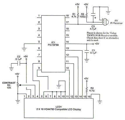
Wait
Syntax:
Fixed Length Delay:
Wait time units
Conditional Delay:
Wait {While | Until} condition
Using a variable to specific US Delay with Warning supression:
Wait timevalue US #OVERRIDEWARNING
Command Availability:
Available on all microcontrollers.
Explanation:
The Wait command will cause the program to wait for either a specified
amount of time (such as 1 second), or while/until a condition is true.
When using the fixed-length delay, there is a variety of units that are available:
| Unit | Length of unit | Delay range |
|---|---|---|
us |
1 microsecond |
1 us - 65535 us |
10us |
10 microseconds |
10 us - 2.55 ms |
ms |
1 millisecond |
1 ms - 65535 ms |
10ms |
10 milliseconds |
10 ms - 2.55 s |
s |
1 second |
1 s - 255 s |
m |
1 minute |
1 min - 255 min |
h |
1 hour |
1 hour - 255 hours |
At one stage, GCBASIC variables could not hold more than 255. The 10us
and 10ms units were added as a way to work around this limit. There is
now no such limit (Wait 1000 ms will work for example), so these are not
really needed. However, you may see them in some older examples or
programs, and the 10us units are sometimes the shortest delay that will
work accurately.
|
Warning
|
PIC Devices Only MS Delays at Clock frequency’s below 28kHz are not supported and will silently fail. US Delays at Clock frequency’s below 250kHz are not supported and will silently fail. US Delays at lower Clock frequency’s is accurate ONLY when nn is divisible by 4. This is caused by the minimum ASM delay loop being a specific number of instructions. US Delays at lower Clock frequency’ when not divisible by 4 will silently accept the nn value and incorrect delays will be produced. + Use #OVERRIDEWARNING to supress warnings.
Delays at Clock frequency’s below 500kHz may be impacted by previous instructions; testing of actual delays is advised. |
Example:
'This code will wait until a button is pressed, then it will flash
'a light every half a second and produce a 440 Hz tone.
#chip 16F819, 8
#define BUTTON PORTB.0
#define SPEAKER PORTB.1
#define LIGHT PORTB.2
Dir BUTTON In
Dir SPEAKER Out
Dir LIGHT Out
'Assumes Button switches on when pressed
Wait Until BUTTON = 1
Wait Until BUTTON = 0
Do
'Flash the light
Set LIGHT On
Wait 500 ms
Set LIGHT Off
'Produce the tone
'440 Hz = 880 changes = tone on for 1.14 ms
Repeat 440
PulseOut SPEAKER, 1140 us
Wait 114 10us 'Wait for 114 x 10 us (1.14 ms)
End Repeat
Loop
To suppress warnings when using US.
dim timevariable as Word
timevariable = 100 // 100 is an example value that assigns the variable.
// Use #OVERRIDEWARNING to prevent warning messages
wait timevariable US #OVERRIDEWARNING
For more help, see Conditions
Fixed Voltage Reference
This is the Fixed Voltage Reference section of the Help file. Please refer the sub-sections for details using the contents/folder view.
FVRInitialize
Syntax:
FVRInitialize ( FVR_OFF | FVR_1x | FVR_2x | FVR_4x )
Command Availability:
Available on all Microchip microcontrollers with the Fixed Voltage Reference (FVR) module.
Explanation:
The method is a subroutine that sets the state of the FVR.
FVR_Off = Fixed Voltage Reference is set to OFF
FVR_1x = Fixed Voltage Reference is set to 1.024v
FVR_2x = Fixed Voltage Reference is set to 2.048v
FVR_4x = Fixed Voltage Reference is set to 4.096v
Using the the following device’s datasheet, as a general case, http://ww1.microchip.com/downloads/en/DeviceDoc/40001419F.pdf that can be downloaded from the device’s page, http://www.microchip.com/wwwproducts/en/pic16f1828 parameter AD06 in table 30-8 at page 359, and the corresponding Note 4, tell us that the Vref voltage (Vref+ minus Vref-) should not be less than 1.8V, regardless of the reference voltage used, in order for the ADC module to work within the datasheet specifications. Also, as Vref- cannot be a negative voltage (voltages below GND) the lowest voltage on it is 0V. Then an FVR of 1.024V cannot be used as VREF+ for the ADC, but only 2.048 and 4.098 values.
The 1.024V FVR value exists for usage with other modules not just the ADC module.
Example:
'// use FVR 4096 as Reference
FVRInitialize ( FVR_4x )
wait while FVRIsOutputReady = false
ADVal = ReadAd(AN0)
'// Turn off FVR
FVRInitialize ( FVR_Off )
For more help, see FVRIsOutputReady
FVRIsOutputReady
Syntax:
user_var = FVRIsOutputReady()
Command Availability:
Available on all Microchip microcontrollers with the Fixed Voltage Reference (FVR) module.
Explanation:
The method is a function that returns the state of the FVR. The returned value can be assigned to a variable to used as function.
The method returns 0 or 1. As follows:
0 = Fixed Voltage Reference output is not ready or not enabled
1 = Fixed Voltage Reference output is ready for use
Example:
'// use FVR 4096 as Reference
FVRInitialize ( FVR_4x )
wait while FVRIsOutputReady = false
ADVal = ReadAd(AN0)
For more help, see FVRInitialize
Interrupts
This is the Interrupt section of the Help file. Please refer the sub-sections for details using the contents/folder view.
Interrupts overview
Introduction
Interrupts are a feature of many microcontrollers. They allow the microcontroller to temporarily pause (interrupt) the code it is running and then start running another piece of code when some event occurs. Once it has dealt with the event, it will return to where it was and continue running the program.
Many events can trigger an interrupt, such as a timer reaching its limit, a serial message being received, or a special pin on the microcontroller receiving a signal.
Using Interrupts
There are two ways to use interrupts in GCBASIC. The first way is to use the On Interrupt command. This will automatically enable a given interrupt, and run a particular subroutine when the interrupt occurs.
The other way to deal with interrupts is to create a subroutine called Interrupt. GCBASIC will call this subroutine whenever an interrupt occurs, and then your code can check the "flag" bits to determine which interrupt has occured, and what should be done about it. If you use this approach, then you’ll need to enable the desired interrupts manually. It is also essential that your code clears the flag bits, or else the interrupt routine will be called repeatedly.
Some combination of these two methods is also possible - the code generated by On Interrupt with check to see if the interrupt is one it recognises. If the interrupt is recognised, On Interrupt will deal with it - if not, the Interrupt subroutine will be called to deal with the interrupt.
The recommended way is to use On Interrupt, as it is both more efficient and easier to set up.
During some sections of code, it is desirable not to have any interrupts occur. If this is the case, then use the IntOff command to disable interrupts at the start of the section, and IntOn to re-enable them at the end. If any interrupt events occur while interrupts are disabled, then they will be processed as soon as interrupts are re-enabled. If the program does not use interrupts, IntOn and IntOff will be removed automatically by GCBASIC.
See Also IntOff, IntOn, On Interrupt
IntOff
Syntax:
IntOff
Command Availability:
Available on Microchip PIC and Atmel AVR microcontrollers with interrupt support. Will be automatically removed on chips without interrupts.
Explanation:
IntOff is used to disable interrupts on the microcontroller. It should
be used at the start of code which is timing-sensitive, and which would
not function correctly if paused and restarted.
It is essential that IntOn is used to turn interrupts on again after the
timing-sensitive code has finished running. If not, no interrupts will
be handled.
It is recommended that IntOff be placed before all code that is timing sensitive, in case interrupts are implemented later.
IntOff will be removed from the assembler if no interrupts are used.
See also IntOn, Interrupts
IntOn
Syntax:
IntOn
Command Availability:
Available on Microchip PIC and Atmel AVR microcontrollers with interrupt support. Will be automatically removed on chips without interrupts.
Explanation:
IntOn is used to enable interrupts on the microcontroller after IntOff
has disabled them. It should be used at the end of code which is
timing-sensitive.
IntOn will be removed from the assembler if no interrupts are used.
See also IntOff, Interrupts
On Interrupt
Syntax:
On Interrupt event Call handler
On Interrupt event Ignore
Command Availability:
Available on Microchip PIC and Atmel AVR microcontrollers with interrupt support.
Explanation:
On Interrupt will add code to call the subroutine handler whenever the interrupt event occurs. When Call is specified, GCBASIC will enable the interrupt, and call the interrupt handler when it occurs. When Ignore is specified, GCBASIC will disable the interrupt handler and prevent it from being called when the event occurs. If the event occurs while the handler is disabled, then the handler will be called as soon as it is re-enabled. The only way to prevent this from happening is to manually clear the flag bit for the interrupt.
There are many possible interrupt events that can occur, and the events vary greatly from chip to chip. GCBASIC will display an error if a given chip cannot support the specified event.
On Interrupt may require the setting or clearing of the interrupt register bit(s), and, On Interrupt may require setting of explicit enable register bits. You should always consult the device datasheet for these On Interrupt additional specific settings of register bits. Typically, you will need define the 1) source event register bit(s) in the main program, and, 2) clear or set the register bit at the start of the of the interrupt handler subroutine.
GCBASIC has many demonstrations showing how to set and enable appropiate interrupt register bits to support the On Interrupt method.
If On Interrupt is used to handle an event, then the Interrupt() subroutine will not be called for that event. However, it will still be called for any events not dealt with by On Interrupt.
Events:
GCBASIC supports the events shown on the table below. Some events are only implemented on a few specialised chips. Events in grey are supported by Microchip PIC and Atmel AVR microcontrollers, events in blue are only supported by some Microchip PIC microcontrollers, and events in red are only supported by Atmel AVR microcontrollers.
Note that GCBASIC doesn’t fully support all of the hardware which can generate interrupts - some work may be required with various system variables to control the unsupported peripherals.
| Event Name | Description | Supported |
|---|---|---|
ADCReady |
The analog/digital converter has finished a conversion |
Microchip&AVR |
BatteryFail |
The battery has failed in some way. This is only implemented on the ATmega406 |
AVR |
CANActivity |
CAN bus activity is taking place |
Microchip |
CANBadMessage |
A bad CAN message has been received |
Microchip |
CANError |
Some CAN error has occured |
Microchip&AVR |
CANHighWatermark |
CAN high watermark reached |
Microchip |
CANRx0Ready |
New message present in buffer 0 |
Microchip |
CANRx1Ready |
New message present in buffer 1 |
Microchip |
CANRx2Ready |
New message present in buffer 2 |
Microchip |
CANRxReady |
New message present |
Microchip |
CANTransferComplete |
Transfer of data has been completed |
AVR |
CANTx0Ready |
Buffer 0 has been sent |
Microchip |
CANTx1Ready |
Buffer 1 has been sent |
Microchip |
CANTx2Ready |
Buffer 2 has been sent |
Microchip |
CANTxReady |
Sending has completed |
Microchip |
CCADCAccReady |
CC ADC accumulate conversion finished (ATmega406 only) |
AVR |
CCADCReady |
CC ADC instantaneous conversion finished (ATmega406 only) |
AVR |
CCADCRegular |
CC ADC regular conversion finished (ATmega406 only) |
AVR |
CCP1 |
The CCP1 module has captured an event |
Microchip |
CCP2 |
The CCP2 module has captured an event |
Microchip |
CCP3 |
The CCP3 module has captured an event |
Microchip |
CCP4 |
The CCP4 module has captured an event |
Microchip |
CCP5 |
The CCP5 module has captured an event |
Microchip |
Comp0Change |
The output of comparator 0 has changed |
Microchip&AVR |
Comp1Change |
The output of comparator 1 has changed |
Microchip&AVR |
Comp2Change |
The output of comparator 2 has changed |
Microchip&AVR |
Crypto |
The KEELOQ module has generated an interrupt |
Microchip |
EEPROMReady |
An EEPROM write has finished |
Microchip&AVR |
Ethernet |
The Ethernet module has generated an interrupt. This must be dealt within the handler. |
Microchip |
ExtInt0 |
External Interrupt pin 0 has been detected |
Microchip&AVR |
ExtInt1 |
External Interrupt pin 1 has been detected |
Microchip&AVR |
ExtInt2 |
External Interrupt pin 2 has been detected |
Microchip&AVR |
ExtInt3 |
External Interrupt pin 3 has been detected |
Microchip&AVR |
ExtInt4 |
External Interrupt pin 4 has been detected |
AVR |
ExtInt5 |
External Interrupt pin 5 has been detected |
AVR |
ExtInt6 |
External Interrupt pin 6 has been detected |
AVR |
ExtInt7 |
External Interrupt pin 7 has been detected |
AVR |
GPIOChange |
The pins on port GPIO have changed |
Microchip |
LCDReady |
The LCD is about to draw a segment |
Microchip&AVR |
LPWU |
The Low Power Wake Up has been detected |
Microchip |
OscillatorFail |
The external oscillator has failed, and the microcontroller is running from an internal oscillator. |
Microchip |
PinChange |
Logic level of PCINT pin has changed |
AVR |
PinChange0 |
Logic level of PCINT0 pin has changed |
AVR |
PinChange1 |
Logic level of PCINT1 pin has changed |
AVR |
PinChange2 |
Logic level of PCINT2 pin has changed |
AVR |
PinChange3 |
Logic level of PCINT3 pin has changed |
AVR |
PinChange4 |
Logic level of PCINT4 pin has changed |
AVR |
PinChange5 |
Logic level of PCINT5 pin has changed |
AVR |
PinChange6 |
Logic level of PCINT6 pin has changed |
AVR |
PinChange7 |
Logic level of PCINT7 pin has changed |
AVR |
PMPReady |
A Parallel Master Port read or write has finished |
Microchip |
PORTChange |
The pins on ports ABCEDEF have changed. This is generic port change interrupt. You must inspect the source to ensure you are handlign the correct interrupt. |
Microchip |
PORTAChange |
The pins on port A have changed |
Microchip |
PORTABChange |
The pins on port A and/or B have changed |
Microchip |
PORTBChange |
The pins on port B have changed |
Microchip&AVR |
PSC0Capture |
The counter for Power Stage Controller 0 matches the value in a compare register, the value of the counter has been captured, or a synchronisation error has occurred |
AVR |
PSC0EndCycle |
Power Stage Controller 0 has reached the end of its cycle |
AVR |
PSC1Capture |
The counter for Power Stage Controller 1 matches the value in a compare register, the value of the counter has been captured, or a synchronisation error has occurred |
AVR |
PSC1EndCycle |
Power Stage Controller 1 has reached the end of its cycle |
AVR |
PSC2Capture |
The counter for Power Stage Controller 2 matches the value in a compare register, the value of the counter has been captured, or a synchronisation error has occurred |
AVR |
PSC2EndCycle |
Power Stage Controller 2 has reached the end of its cycle |
AVR |
PSPReady |
A Parallel Slave Port read or write has finished |
Microchip |
PWMTimeBase |
The PWM time base matches the PWM Time Base Period register (PTPER) |
Microchip |
SPIReady |
The SPI module has finished the previous transfer |
AVR |
SPMReady |
A write to program memory by the spm instruction has finished |
AVR |
SPPReady |
A SPP read or write has finished |
Microchip |
SSP1Collision |
SSP1 has detected a bus collision |
Microchip |
SSP1Ready |
The SSP/SSP1/MSSP1 module has finished sending or receiving |
Microchip |
SSP2Collision |
SSP2 has detected a bus collision |
Microchip |
SSP2Ready |
The SSP2/MSSP2 module has finished sending or receiving |
Microchip |
Timer0Capture |
An input event on the pin ICP0 has caused the value of Timer 0 to be captured in the ICR0 register |
AVR |
Timer0Match1 |
Timer 0 matches the Timer 0 output compare register A (OCR0A) |
AVR |
Timer0Match2 |
Timer 0 matches the Timer 0 output compare register B (OCR0B) |
AVR |
Timer0Overflow |
Timer 0 has overflowed |
Microchip&AVR |
Timer1Capture |
An input event on the pin ICP1 has caused the value of Timer 1 to be captured in the ICR1 register |
AVR |
Timer1Error |
The Timer 1 Fault Protection unit has been detected by an input on the INT0 pin |
AVR |
Timer1Match1 |
Timer 1 matches the Timer 1 output compare register A (OCR1A) |
AVR |
Timer1Match2 |
Timer 1 matches the Timer 1 output compare register B (OCR1B) |
AVR |
Timer1Match3 |
Timer 1 matches the Timer 1 output compare register C (OCR1C) |
AVR |
Timer1Match4 |
Timer 1 matches the Timer 1 output compare register D (OCR1D) |
AVR |
Timer1Overflow |
Timer 1 has overflowed |
Microchip&AVR |
Timer2Match |
Timer 2 matches the Timer 2 output compare register (PR2) |
Microchip |
Timer2Match1 |
Timer 2 matches the Timer 2 output compare register A (OCR2A) |
AVR |
Timer2Match2 |
Timer 2 matches the Timer 2 output compare register B (OCR2B) |
AVR |
Timer2Overflow |
Timer 2 has overflowed |
AVR |
Timer3Capture |
An input event on the pin ICP3 has caused the value of Timer 3 to be captured in the ICR3 register |
AVR |
Timer3Match1 |
Timer 3 matches the Timer 3 output compare register A (OCR3A) |
AVR |
Timer3Match2 |
Timer 3 matches the Timer 3 output compare register B (OCR3B) |
AVR |
Timer3Match3 |
Timer 3 matches the Timer 3 output compare register C (OCR3C) |
AVR |
Timer3Overflow |
Timer 3 has overflowed |
Microchip&AVR |
Timer4Capture |
An input event on the pin ICP4 has caused the value of Timer 4 to be captured in the ICR4 register |
AVR |
Timer4Match |
Timer 4 matches the Timer 4 output compare register (PR4) |
Microchip |
Timer4Match1 |
Timer 4 matches the Timer 4 output compare register A (OCR4A) |
AVR |
Timer4Match2 |
Timer 4 matches the Timer 4 output compare register B (OCR4B) |
AVR |
Timer4Match3 |
Timer 4 matches the Timer 4 output compare register C (OCR4C) |
AVR |
Timer4Overflow |
Timer 4 has overflowed |
AVR |
Timer5CAP1 |
An input on the CAP1 pin has caused the value of Timer 5 to be captured in CAP1BUF |
Microchip |
Timer5CAP2 |
An input on the CAP2 pin has caused the value of Timer 5 to be captured in CAP2BUF |
Microchip |
Timer5CAP3 |
An input on the CAP3 pin has caused the value of Timer 5 to be captured in CAP3BUF |
Microchip |
Timer5Capture |
An input event on the pin ICP5 has caused the value of Timer 5 to be captured in the ICR5 register |
AVR |
Timer5Match1 |
Timer 5 matches the Timer 5 output compare register A (OCR5A) |
AVR |
Timer5Match2 |
Timer 5 matches the Timer 5 output compare register B (OCR5B) |
AVR |
Timer5Match3 |
Timer 5 matches the Timer 5 output compare register C (OCR5C) |
AVR |
Timer5Overflow |
Timer 5 has overflowed |
Microchip&AVR |
Timer6Match |
Timer 6 matches the Timer 6 output compare register (PR6) |
Microchip |
Timer7Overflow |
Timer 7 has overflowed |
Microchip |
Timer8Match |
Timer 8 matches the Timer 8 output compare register (PR8) |
Microchip |
Timer10Match |
Timer 10 matches the Timer 10 output compare register (PR10) |
Microchip |
Timer12Match |
Timer 12 matches the Timer 12 output compare register (PR12) |
Microchip |
TWIConnect |
The Atmel AVR has been connected to or disconnected from the TWI (I2C) bus |
Microchip&AVR |
TWIReady |
The TWI has finished the previous transmission and is ready to send or receive more data |
Microchip&AVR |
UsartRX1Ready |
UART/USART 1 has received data |
Microchip&AVR |
UsartRX2Ready |
UART/USART 2 has received data |
Microchip&AVR |
UsartRX3Ready |
UART/USART 3 has received data |
AVR |
UsartRX4Ready |
UART/USART 4 has received data |
AVR |
UsartTX1Ready |
UART/USART 1 is ready to send data |
Microchip&AVR |
UsartTX1Sent |
UART/USART 1 has finished sending data |
AVR |
UsartTX2Ready |
UART/USART 2 is ready to send data |
Microchip&AVR |
UsartTX2Sent |
UART/USART 2 has finished sending data |
AVR |
UsartTX3Ready |
UART/USART 3 is ready to send data |
AVR |
UsartTX3Sent |
UART/USART 3 has finished sending data |
AVR |
UsartTX4Ready |
UART/USART 4 is ready to send data |
AVR |
UsartTX4Sent |
UART/USART 4 has finished sending data |
AVR |
USBEndpoint |
A USB endpoint has generated an interrupt |
AVR |
USB |
The USB module has generated an interrupt. This must be dealt with in the handler. |
Microchip&AVR |
USIOverflow |
The USI counter has overflowed from 15 to 0 |
AVR |
USIStart |
The USI module has detected a start condition |
AVR |
VoltageFail |
The input voltage has dropped too low |
Microchip |
VoltageRegulator |
An interrupt has been generated by the voltage regulator (ATmega16HVA only) |
AVR |
WakeUp |
The Wake-Up timer has overflowed |
AVR |
WDT |
An interrupt has been generated by the Watchdog Timer |
AVR |
Example 1:
'This program increments a counter every time Timer1 overflows
#chip 16F877A, 20
'LCD connection settings
#define LCD_IO 4
#define LCD_WIDTH 20 ;specified lcd width for clarity only. 20 is the default width
#define LCD_DB4 PORTD.4
#define LCD_DB5 PORTD.5
#define LCD_DB6 PORTD.6
#define LCD_DB7 PORTD.7
#define LCD_RS PORTD.0
#define LCD_RW PORTD.1
#define LCD_Enable PORTD.2
InitTimer1 Osc, PS1_1/8
StartTimer 1
CounterValue = 0
Wait 100 ms
Print "Int Test"
On Interrupt Timer1Overflow Call IncCounter
Do
CLS
Print CounterValue
Wait 100 ms
Loop
Sub IncCounter
CounterValue ++
End Sub
Example 2:
'This example reflects the input signal on the output port.
#chip mega328p, 16
#option explicit
'set out SOURCE interrupt port as an output
dir portb.0 in
'set/enable the mask for the specific input port
'this is crutial - for a lot of the On Interrupt methods you will need to specify the interrupt source via a mask.bit.
PCINT0 = 1
'set out signal port as an output
dir portB.5 out
'setup the On Interrupt method
On Interrupt PinChange0 Call TogglePin
'maintain a loop
do
loop
'handle the output signal
'Note. The AVR automatically clears the Interrupt. Please study the datasheet for each specific microcontroller
sub togglePin
portb.5 = !pinb.5
end sub
Example 3:
'This example reflects the input signal on the output port from the external interrupt port.
#Chip mega328p, 16
#option explicit
'Set external interrupt INTO input pin as an input
dir portd.2 in
'set out signal port as an output
dir portB.5 out
'hardware interrupt on Port D2
INT0 = 1
'set interrupt to a failing or rising edge
'interrupt on falling edge
EICRA = b'00000010'
'or, alternatively you can set to a rising edge
'EICRA = b'00000011'
'set out signal port as an output
dir portB.5 out
'setup the On Interrupt method on external interrupt 0
On Interrupt EXTINT0 Call togglePin
'maintain a loop
do
loop
'handle the output signal
'Note. The AVR automatically clears the Interrupt. Please study the datasheet for each specific microcontroller
sub togglePin
portb.5 = !pinb.5
end sub
For more help, see InitTimer0 article contains an example of using Timer 0 and On Interrupt to generate a Pulse Width Modulation signal to control a motor.
On Interrupt: The default handler
Introduction
GCBASIC supports a default interrupt handler in two modes:
-
You can define the interrupt flags and the default handler (a sub routine) will executed
-
You can define an On Interrupt event Call handler where the handler is executed that matches the event and where all other define/valid events are handled by the default handler (a sub routine), The easiest way to write an interrupt handler is to write it in GCBASIC in conjunction with the On Interrupt statement. On Interrupt tells microcontroller to activate its internal interrupt handling and to jump to a predetermined interrupt handler (a sub routine that has been defined) when the interrupt handler (the sub routine) has completed processing returns to correct address in the program. See On Interrupt.
This method of supports the handling interrupts by enabling a default interrupt subroutine.
Example 1
This example shows if an event occurs the microcontroller will be program to jump to the interrupt vector and the program will not know the event type, it will simple execute the Interrupt subroutine. This code is not intended as a meaningful solution and intended to show the functionality only. An LED is attached to PORTB.1 via a suitable resistor. It will light up when the Interrupt event has occurred.
#chip 16f877a, 4
dir PORTB.1 out
Set PORTB.1 Off
'Note: there is NO On Interrupt handler
InitTimer1 Osc, PS1_8
SetTimer 1, 1
StartTimer 1
'Manually set Timer1Overflow to the overflow event
'this will event will be handled by the Interrupt sub routine
TMR1IE = 1
end
Sub Interrupt
Set PORTB.1 On
TMR1IF = 0
End Sub
Example 2
Any events that are not dealt with by On Interrupt will result in the code in the Interrupt subroutine executing. This example shows the operation of two interrupt handlers - is not intended as a meaningful solution.
LEDs are attached to PORTB.1 and PORTB.2 via suitable resistors. They will light up when the Interrupt events occur.
#chip 16f877a, 4
On Interrupt Timer1Overflow call Overflowed
dir PORTB.1 out
Set PORTB.1 Off
dir PORTB.2 out
Set PORTB.2 Off
InitTimer1 Osc, PS1_8
SetTimer 1, 1
StartTimer 1
InitTimer2 PS2_16, PS2_16
SetTimer 2, 255
StartTimer 2
'Manually set Timer2Overflow to create a second event
'this will event will be handled by the Interrupt sub routine
TMR2IE = 1
end
Sub Interrupt
Set PORTB.2 On
TMR2IF = 0
End Sub
Sub Overflowed
Set PORTB.1 On
TMR1IF = 0
End Sub
Keypad
This is the Keypad section of the Help file. Please refer the sub-sections for details using the contents/folder view.
Keypad Overview
Introduction
The keypad routines allow for a program to read from a 4 x 4 matrix keypad.
There are two ways that the keypad routines can be set up. One option is
to connect the wires from the keypad in a particular order, and then to
set the KeypadPort constant. The other option is to connect the keypad
in whatever way is easiest, and then set the KEYPAD_ROW_x and
KEYPAD_COL_x constants. The option (setting KeypadPort) will
generate slightly more efficient code.
Configuration using KEYPAD_ROW_x and KEYPAD_COL_x:
These constants must be set:
| Constant Name | Controls | Default Value |
|---|---|---|
|
The pin on the microcontroller that connects to the Row 1 pin on the keypad |
N/A |
|
The pin on the microcontroller that connects to the Row 2 pin on the keypad |
N/A |
|
The pin on the microcontroller that connects to the Row 3 pin on the keypad |
N/A |
|
The pin on the microcontroller that connects to the Row 4 pin on the keypad |
N/A |
|
The pin on the microcontroller that connects to the Col 1 pin on the keypad |
N/A |
|
The pin on the microcontroller that connects to the Col 2 pin on the keypad |
N/A |
|
The pin on the microcontroller that connects to the Col 3 pin on the keypad |
N/A |
|
The pin on the microcontroller that connects to the Col 4 pin on the keypad |
N/A |
If using a 3 x 3 keypad, do not set the KEYPAD_ROW_4 or KEYPAD_COL_4
constants.
Configuration using KeypadPort:
When setting up the keypad code using the KeypadPort constant, only
KeypadPort needs to be set.
Pull-ups or pull-downs go on the columns only, and are typically 4.7k to 10k in value.
| Constant Name | Controls | Default Value |
|---|---|---|
|
The port on the microcontroller chip that the keypad is connected to. |
N/A |
Configuration when using Pull down resistors
The keypad routine has a feature when using pull-down resistors, simply add the constant to your program and the and the scan logic will be inverted appropriately.
| Constant Name | Controls | Default Value |
|---|---|---|
|
Support pull down resistors. |
N/A |
For this to work, the keypad must be connected as follows:
| Microcontroller port pin | Keypad connector |
|---|---|
0 |
Row 1 |
1 |
Row 2 |
2 |
Row 3 |
3 |
Row 4 |
4 |
Column 1 |
5 |
Column 2 |
6 |
Column 3 |
7 |
Column 4 |
Note: To use a 3 x 3 keypad in this mode, the pins on the microcontroller for any unused columns must be pulled up.
KeypadData
Syntax:
var = KeypadData
Command Availability:
Available on all microcontrollers.
Explanation:
This function will return a value corresponding to the key that is
pressed on the keypad. Note that if two or more keys are pressed, then
only one value will be returned.
var can have one of the following values:
| Value | Constant Name | Key Pressed |
|---|---|---|
0 |
0 |
|
1 |
1 |
|
2 |
2 |
|
3 |
3 |
|
4 |
4 |
|
5 |
5 |
|
6 |
6 |
|
7 |
7 |
|
8 |
8 |
|
9 |
9 |
|
10 |
KEY_A |
A |
11 |
KEY_B |
B |
12 |
KEY_C |
C |
13 |
KEY_D |
D |
14 |
KEY_STAR |
Asterisk/Star (*) |
15 |
KEY_HASH |
Hash (#) |
255 |
KEY_NONE |
None |
Example:
'Program to show the value of the last pressed key on the LCD
#chip 18F4550, 20
'LCD connection settings
#define LCD_IO 4
#define LCD_WIDTH 20 ;specified lcd width for clarity only. 20 is the default width
#define LCD_DB4 PORTD.4
#define LCD_DB5 PORTD.5
#define LCD_DB6 PORTD.6
#define LCD_DB7 PORTD.7
#define LCD_RS PORTD.0
#define LCD_RW PORTD.1
#define LCD_Enable PORTD.2
'Keypad connection settings
#define KeypadPort PORTB
'Main loop
Do
'Get key
Temp = KeypadData
'If a key is pressed, then display it
If Temp <> KEY_NONE Then
CLS
Print Temp
Wait 100 ms
End If
Loop
For more help, see Keypad Overview
KeypadRaw
Syntax:
largevar = KeypadRaw
Command Availability:
Available on all microcontrollers.
Explanation:
This function will return a 16 bit value, in which each bit corresponds to a key on the keypad. If the key is pressed its bit will hold 1, and if it is released its bit will contain a 0.
This table shows the key that each bit corresponds to:
| Bit | Key Position (row, col) | Common Key Symbol |
|---|---|---|
15 |
1,1 |
1 |
14 |
1,2 |
2 |
13 |
1,3 |
3 |
12 |
1,4 |
A |
11 |
2,1 |
4 |
10 |
2,2 |
5 |
9 |
2,3 |
6 |
8 |
2,4 |
B |
7 |
3,1 |
7 |
6 |
3,2 |
8 |
5 |
3,3 |
9 |
4 |
3,4 |
C |
3 |
4,1 |
* |
2 |
4,2 |
0 |
1 |
4,3 |
# |
0 |
4,4 |
D |
Example:
'Program to show the keypad status using LEDs
#chip 16F877A, 20
'Keypad connection settings
#define KeypadPort PORTB
'LEDs
#define LED1 PORTC
#define LED2 PORTD
Dir LED1 Out
Dir LED2 Out
'Declare a 16 bit variable for the key value
Dim KeyStatus As Word
'Main loop
Do
'Get key
KeyStatus = KeypadRaw
'Display
LED1 = KeyStatus_H 'High Byte
LED2 = KeyStatus 'Low Byte
Loop
For more help, see Keypad Overview
Graphical LCD
This is the GLCD section of the Help file. Please refer the sub-sections for details using the contents/folder view.
GLCD Overview
The GLCD commands are used to control a Graphical Liquid Crystal Display (GLCD) based on the a number of GLCD chipsets. These are often 128x64 pixel displays but the size can vary. GLCD devices draw graphical elements by enabling or disabling pixels.
A GLCD is an upgrade from the popular 16x2 LCDs (see Liquid Crystal Display Overview ) but the GLCD allows full graphical control of the display.
Typical displays are
-
Color or mono displays
-
Low power white LED, OLED with or without back-light
-
e-Paper with low power consumption
-
Driven by on-board interface chipsets amd/or interface controllers
-
The GLCDs are very common and well documented
-
Small to large view areas
-
Typically requires from 3-pin to 36-pin header connections and 10K contrast pot
-
Typically have back-lit pixels
-
Require memory in the microcontroller to support graphial operations or can be used in text and picture mode
GCBASIC makes this type of device easier to control with the commands for the GLCD.
Microcontroller Requirements: Specific GLCDs require different configurations of a microcontroller. Parameters include
-
Communications protocol: These incldue 8 wire bus, I2C, SPI etc
-
Operating votlage: These are typically 3.3v or 5.v
-
Memory required: For full GLCD capabilites you will require 1k or more, for text only and JPG mode low memory devices are supported
Review your choice of microcontroller and GLCD carefully before commencing your project.
| # | ChipSet | Size | Pixels | Depth | Type | I/O | Support | Operating | Comments | Requirements | Assessment |
|---|---|---|---|---|---|---|---|---|---|---|---|
1 |
KS0108 |
2.9 inch and less. various sizes |
128 * 64 |
Large |
Mono |
LCD typically with backlight |
8-bit parallel PIC and AVR: Software device specific protocol |
Typically operates at VCC 5. Always check voltage specifications 8-bit bus required. |
Bit 7 of the bus is read/write – this could cause potential lockup – this is low risk. Uses the KS0107B (or NT7107C) a 64-channel common driver which generates the timing signal to control the two KS0108B segment drivers. |
Requires 12 ports/connections. |
These are low cost mono devices. |
2 |
ILI9481 |
3.2inch |
320 * 240 |
Large |
Color |
TFT LCD 8-bit parallel |
PIC: Set per bit. AVR: via Shield set via AND PORT command |
+VCC from 2.7 to 5. Always check voltage specifications |
UNO shield is excellent. Very fast display. |
SPI requires 4 ports plus 2 ports. Typically 6 in total. |
Good GLCD with very good GLCD performance. |
3 |
PCD8544 |
1.77inch |
Nokia 3310 or 5110 |
160 * 128 |
Small Mono LCD with LED |
SPI |
PIC and AVR: Device specific SPI command, all in software. |
Display can operate in text mode only for low RAM microcontrollers as full GLCD capabilities requires 512bytes of RAM. +VCC 3.3. Always check voltage specifications Nice display. Sensitive to operating voltages. |
Minimum RAM required is 512 bytes then add user variables for graphics mode, this display can operate in text mode only for low RAM microcontrollers. |
SPI requires 4 ports plus 2 ports. Typically 6 in total. |
Good for cost and performance |
4 |
ILI9341 |
2.8 Inch or 3.2 Inch |
320 * 240 |
Medium |
Color TFT |
SPI PIC and AVR: Hardware and software SPI |
Typically operates at VCC 5. Always check voltage specifications |
+VCC from 2.7 to 5. Always check voltage specifications |
Very nice display. |
SPI requires 4 ports plus 2 ports. Typically 6 in total. |
Good for cost and performance |
5 |
SSD1289 |
3.2inch |
240 * 320 |
Large |
Color |
TFT LCD |
16-bit parallel AVR: Software device specific protocol. |
Typically operates at VCC 5. Always check voltage specifications |
Mega2560 shield required. |
Connectivity requires 20 ports. |
Good for Mega2560 type shields |
6 |
ST7735 |
1.8 Inch |
128 * 64 |
Large |
Color |
TFT LCD |
SPI |
PIC and AVR: Hardware and software SPI |
Typically operates at VCC 5. Always check voltage specifications Very nice display. |
SPI requires 4 ports plus 2 ports. Typically 6 in total. |
Good for cost and performance |
7 |
ST7735R |
1.8 Inch |
128 * 160 |
Large |
Color |
TFT LCD |
SPI |
PIC and AVR: Hardware and software SPI |
Typically operates at VCC 5. Always check voltage specifications Very nice display. |
SPI requires 4 ports plus 2 ports. Typically 6 in total. |
Good for cost and performance |
8 |
ST7735R_160_80 |
1.8 Inch |
160 * 80 |
Large |
Color |
TFT LCD |
SPI |
PIC and AVR: Hardware and software SPI |
Typically operates at VCC 5. Always check voltage specifications Very nice display. |
SPI requires 4 ports plus 2 ports. Typically 6 in total. |
Good for cost and performance |
9 |
ILI9340 |
2.2 Inch |
240 * 320 |
Medium |
Mono |
TFT LCD |
SPI |
PIC and AVR: Hardware and software SPI |
Typically operates at VCC 5. Always check voltage specifications |
SPI requires 4 ports plus 2 ports. Typically 6 in total. |
Good for cost and performance |
10 |
ILI9486L or ILI9486 |
4inch |
RPI 240 * 320 |
Large |
Color |
TFT LCD |
SPI and 8Bit Bus |
PIC and AVR: Hardware and software SPI AVR: 8Bit Bus using an UNO Shield. PIC: 8bit port suppported. |
Typically operates at VCC 5. Always check voltage specifications Great pixel display. |
SPI requires 4 ports plus 2 ports. Typically 6 in total. 8Bit Bus requires 8 ports plus 4 control ports. Typically 13 in total using an 8bit bus solution. |
An expensive option |
11 |
Nexion |
ITEAD Nexion |
240 * 320 to 800 * 480 |
Large - 2.4 to 7inches |
Color |
TFT LCD |
Serial - hardware or software serial is supported. |
Nextion specfic and GLCD command set |
Typically operates at VCC 5 with external power supply. Always check voltage specifications Great command set, you need to learn the GUI and then interface to GCBASIC. |
2 ports for the read/write serial operations. |
A very nice option but if you need flexibility then the best! |
12 |
SH1106 |
1.3 inch or 0.96inch |
128 * 64 |
Small |
Mono OLED |
I2C |
PIC and AVR: Hardware and software I2C |
Always at 3.3v. Always check voltage specifications |
RAM for Full Mode GLCD is 1024 bytes or Low Memory GLCD is 128 bytes or 0 bytes for Text GLCD Mode then add user variables for graphics mode. |
I2C requires 2 ports. |
Good OLED display, excellent value for money |
13 |
SDD1306 |
0.96inch |
128 * 64 |
Small |
Mono |
OLED |
I2C and SPI |
PIC and AVR: Hardware and software I2C, and software SPI |
RAM for Full Mode GLCD is 1024 bytes or Low Memory GLCD is 128 bytes or 0 bytes for Text GLCD Mode then add user variables for graphics mode. Typically operates at VCC 5. Always check voltage specifications Very good OLED display. Driver supports gaming. Minimum RAM required is 1024 bytes then add user variables for graphics mode. Display can operate in text mode only for low RAM microcontrollers |
SPI requires 4 ports plus 2 ports. Typically 6 in total. I2C requires 2 ports. |
Good OLED display, excellent value for money |
14 |
SDD1306 Twin Screen |
0.96inch * 2 |
128 * 128 |
Small |
Mono |
OLED |
I2C and SPI |
PIC and AVR: Hardware and software I2C, and software SPI |
RAM for Full Mode GLCD is 2048 bytes or Low Memory GLCD is 128 bytes or 0 bytes for Text GLCD Mode then add user variables for graphics mode. Typically operates at VCC 5. Always check voltage specifications Very good OLED display. Driver supports gaming. Minimum RAM required is 1024 bytes then add user variables for graphics mode. Display can operate in text mode only for low RAM microcontrollers |
SPI requires 4 ports plus 3 ports. Typically 7 in total. I2C requires 2 ports. |
Good OLED display, excellent value for money |
15 |
SDD1306_32 |
0.96inch |
128 * 32 |
Very small |
Mono |
OLED |
I2C and SPI |
PIC and AVR: Hardware and software I2C, and software SPI |
RAM for Full Mode GLCD is 512 bytes or Low Memory GLCD is 128 bytes or 0 bytes for Text GLCD Mode then add user variables for graphics mode. Typically operates at VCC 5. Always check voltage specifications Best small OLED display. Driver supports gaming. Minimum RAM required is 512 bytes then add user variables for graphics mode, this display can operate in text mode only for low RAM microcontrollers |
SPI requires 4 ports plus 2 ports. Typically 6 in total. I2C requires 2 ports. |
Good OLED display, excellent value for money |
16 |
ST7920 |
2.9inch |
128 * 64 |
Large |
Mono |
LCD typically with backlight 8-bit parallel |
PIC and AVR: Software device specific protocol. |
Typically operates at VCC 5. Always check voltage specifications |
8-bit bus required. Bit 7 of the bus is read/write – this could cause potential lockup – this is low risk. This looks like a KS0108 but it is NOT! Supports Chinese font set. |
Requires 12 ports. |
A very slow device. |
17 |
HX8347G |
2.2inch |
240 * 320 |
Large |
Color |
TFT LCD |
SPI |
AVR 8 bit bus |
Typically operates at VCC 5. Always check voltage specifications Great pixel display. |
Controller requires 8 ports plus 5 control ports. Typically 13 in total with an UNO shield. |
An very nice display |
18 |
SDD1331 |
0.96inch |
96 * 48 |
Small |
Color |
OLED |
SPI |
PIC and AVR: Hardware and software I2C, and software SPI |
Typically operates at VCC 5. Always check voltage specifications |
SPI requires typically 6 in total. |
Very good color OLED display, excellent value for money |
19 |
ILI9326 |
3.00inch |
400 * 320 |
Large |
Color |
OLED |
8 bit bus |
PIC and AVR: 8 bit bus |
Typically operates at VCC 3.3. Always check voltage specifications |
Requires typically 13 in total plus 0v, VCC and LED. |
Good color OLED display, good value for money as it is fast. But, the rotate is all executed in software and this does slow down processing.
|
20 |
NT7108C |
2.9 inch and less. various sizes |
128 * 64 |
Large |
Mono |
LCD typically with backlight |
8-bit parallel PIC and AVR: Software device specific protocol |
Typically operates at VCC 5. Always check voltage specifications 8-bit bus required. |
Look similar to KS0108, but, it is NOT the same, hence this driver. Uses the Winstar’s WDG0151-TMI module, which is a 128×64 pixel monochromatic display. This uses two Neotic display controller chips: NT7108C and NT7107C. The WDG0151 module contains two sets of it to drive 128 segments. On the other hand, the KS0107B (or NT7107C) is a 64-channel common driver which generates the timing signal to control the two KS0108B segment drivers.
|
Requires 12 ports/connections. |
These are medium cost mono devices. |
21 |
T6963_64 |
4inches by 2inches |
240 * 64 |
Large |
Mono |
LCD typically with backlight |
8-bit parallel PIC and AVR: Software device specific protocol |
Typically operates at VCC 5. Always check voltage specifications 8-bit bus required. |
Operating similar to KS0108 and an LCD. segment drivers.
|
Requires 12 ports/connections. |
These are medium cost mono devices. |
22 |
T6963_128 |
4inches by 2inches |
240 * 128 |
Large |
Mono |
LCD typically with backlight |
8-bit parallel PIC and AVR: Software device specific protocol |
Typically operates at VCC 5. Always check voltage specifications 8-bit bus required. |
Operating similar to KS0108 and an LCD. segment drivers.
|
Requires 12 ports/connections. |
These are medium cost mono devices. |
23 |
UC1601 |
4.00inch |
132 * 22 |
Medium |
Mono |
OLED |
I2C and SPI |
PIC and AVR: Hardware and software I2C, and software SPI |
RAM for Full Mode GLCD is 396 bytes or Low Memory GLCD is 128 bytes or 0 bytes for Text GLCD Mode then add user variables for graphics mode. Typically operates at VCC 2.8v. Always check voltage specifications Very good display. Driver supports gaming. Minimum RAM required is 396 bytes then add user variables for graphics mode. |
Requires up to 5 ports/connections. |
Low cost device |
24 |
SDD1351 |
1.50inch |
128 * 128 |
Small |
Color |
OLED |
SPI |
PIC and AVR: Hardware and software I2C, and software SPI |
Typically operates at VCC 3.3 or 5. Always check voltage specifications |
SPI requires typically 6 in total. |
Very good color OLED display, excellent value for money |
25 |
Waveshare e-Paper |
Various Size from 2.13 to 7.5 inches |
104 * 112 to 640 * 384 |
Small to very large |
Black and White |
Microencapsulated Electrophoretic Display |
SPI |
PIC and AVR: Hardware and software I2C, and software SPI |
Typically operates at VCC 3.3. Always check voltage specifications |
SPI requires typically 6 in total. |
Very good color e-Paper displays, excellent value for money Display can operate in text mode only for low RAM microcontrollers using SRAM solution. |
26 |
ST7789 |
2.0 Inch |
240 * 240 or 320 * 240 |
Medium |
Color TFT |
SPI PIC and AVR: Hardware and software SPI |
Typically operates at 3v3. Always check voltage specifications |
+VCC from 3v3. Always check voltage specifications |
Very nice display. |
SPI requires 3 ports (data, clock & command/data) plus 1 port ( reset ). Typically 4 in total. |
Good for cost and performance |
27 |
ST7735R_160_80 |
1.8 Inch |
160 * 80 |
Large |
Color |
TFT LCD |
SPI |
PIC and AVR: Hardware and software SPI |
Typically operates only at VCC 3.3. Always check voltage specifications Very nice display. |
SPI requires 4 ports plus 2 ports. Typically 6 in total. |
Good for cost and performance |
28 |
ILI9488 |
3.2inch |
320 * 240 |
Large |
Color |
TFT LCD SPI |
PIC/&AVR: SPI Only |
+VCC from 3v3 to 5. GLCD I/O is ONLY 3v3. Always check voltage specifications. |
Display is good, however, slower than comparable (size) GLCDs as the color definitions are four bytes ( typical color definitions are two bytes) |
SPI requires 4 ports plus 2 ports. Typically 6 in total. |
Acceptable GLCD performance. |
29 |
ST7567 |
1.9inch |
128 * 64 |
Medium |
Mono |
LCD |
I2C and SPI |
PIC and AVR: Software I2C, and, hardware software SPI. Harware IC2 fails as the ST7567 does not comply witht the I2C standard. |
+VCC from 3v3 to 5. GLCD I/O is ONLY 3v3. Always check voltage specifications. |
SPI requires 4 ports plus 2 ports. Typically 6 in total. I2C requires 2 ports. |
Typically operates at VCC 3v3 but may support 5v0. Always check voltage specifications Very good LCD display. Driver supports gaming. Minimum RAM required is 1024 bytes then add user variables for graphics mode. |
Setup:
You must include the glcd.h file at the top of your program. The file
needs to be in brackets as shown below.
#include <GLCD.h>
Defines:
There are several connections that must be defined to use the GLCD commands with a GLCD display. The I/O pin is the pin on the Microchip PIC or the Atmel AVR microcontroller that is connected to that specific pin on the graphical LCD.
Example: KS0108 connectivity
#define GLCD_RW _I/O pin_ ‘Read/Write pin connection
#define GLCD_RESET _I/O pin_ ‘Reset pin connection
#define GLCD_CS1 _I/O pin_ ‘CS1 pin connection
#define GLCD_CS2 _I/O pin_ ‘CS2 pin connection
#define GLCD_RS _I/O pin_ ‘RS pin connection
#define GLCD_ENABLE _I/O pin_ ‘Enable pin Connection
#define GLCD_DB0 _I/O pin_ ‘Data pin 0 Connection
#define GLCD_DB1 _I/O pin_ ‘Data pin 1 Connection
#define GLCD_DB2 _I/O pin_ ‘Data pin 2 Connection
#define GLCD_DB3 _I/O pin_ ‘Data pin 3 Connection
#define GLCD_DB4 _I/O pin_ ‘Data pin 4 Connection
#define GLCD_DB5 _I/O pin_ ‘Data pin 5 Connection
#define GLCD_DB6 _I/O pin_ ‘Data pin 6 Connection
#define GLCD_DB7 _I/O pin_ ‘Data pin 7 Connection
#define GLCD_PROTECTOVERRUN 'prevent screen overdrawing 'SSD1306 GLCD only
#define GLCDDirection 'Invert GLCD Y axis 'KS0108 GCD only
Common commands supported across the range of supported GLCDs are:
| Command | Purpose | Example |
|---|---|---|
|
Clear screen of GLCD |
|
|
Print string of characters on GLCD using GCB font set |
|
|
Print character on GLCD using GCB font set |
|
|
Print characters on GLCD using GCB font set |
|
|
Draw a box on the GLCD to a specific size |
|
|
Draw a box on the GLCD to a specific size that is filled with the foreground colour. |
|
|
Draw a line on the GLCD to a specific length that is filled with the specific attribute. |
|
|
Set a pixel on the GLCD at a specific position that is set with the specific attribute. |
|
Public variable supported across the range of supported GLCDs are shown in the table below. These variables control the user definable parameters of a specific GLCD.
| Variable | Purpose | Type |
|---|---|---|
|
Color of GLCD background. |
Can be monochrome or color. |
|
Color of GLCD foreground. |
Can be monochrome or color. |
|
Width of the current GLCD font. |
Default is 6 pixels. |
|
Size of the current GLCD font. |
Default is 0.+ This equates to the standard GCB font set. |
|
Size of the current GLCD font. |
Default is 1.+ This equates to the 8 pixel high. |
For color TFT displays any color can be defined using a valid hexidecimal word value between 0x0000 to 0xFFFF., see http://www.barth-dev.de/online/rgb565-color-picker/ for a wider range of color parameters.
The following color constants are prevent-defined.
TFT_BLACK 0x0000
TFT_NAVY 0x000F
TFT_DARKGREEN 0x03E0
TFT_DARKCYAN 0x03EF
TFT_MAROON 0x7800
TFT_PURPLE 0x780F
TFT_OLIVE 0x7BE0
TFT_LIGHTGREY 0xC618
TFT_DARKGREY 0x7BEF
TFT_BLUE 0x001F
TFT_GREEN 0x07E0
TFT_CYAN 0x07FF
TFT_RED 0xF800
TFT_MAGENTA 0xF81F
TFT_YELLOW 0xFFE0
TFT_WHITE 0xFFFF
TFT_ORANGE 0xFD20
TFT_GREENYELLOW 0xAFE5
TFT_PINK 0xF81F
This example shows how to drive a KS0108 based Graphic LCD module with the built in commands of GCBASIC. See Graphic LCD for details, this is an external web site.
Example:
;Chip Settings
#chip 16F886,16
'#config MCLRE = on 'enable reset switch on CHIPINO
#include <GLCD.h>
;Defines (Constants)
#define GLCD_RW PORTB.1 'D9 to pin 5 of LCD
#define GLCD_RESET PORTB.5 'D13 to pin 17 of LCD
#define GLCD_CS1 PORTB.3 'D12 to actually since CS1, CS2 can be inverted
#define GLCD_CS2 PORTB.4 'D11 to actually since CS1, CS2 can be inverted
#define GLCD_RS PORTB.0 'D8 to pin 4 D/I pin on LCD
#define GLCD_ENABLE PORTB.2 'D10 to Pin 6 on LCD
#define GLCD_DB0 PORTC.7 'D0 to pin 7 on LCD
#define GLCD_DB1 PORTC.6 'D1 to pin 8 on LCD
#define GLCD_DB2 PORTC.5 'D2 to pin 9 on LCD
#define GLCD_DB3 PORTC.4 'D3 to pin 10 on LCD
#define GLCD_DB4 PORTC.3 'D4 to pin 11 on LCD
#define GLCD_DB5 PORTC.2 'D5 to pin 12 on LCD
#define GLCD_DB6 PORTC.1 'D6 to pin 13 on LCD
#define GLCD_DB7 PORTC.0 'D7 to pin 14 on LCD
Start:
GLCDCLS
GLCDPrint 0,10,"Hello" 'Print Hello
wait 5 s
GLCDPrint 0,10, "ASCII #:" 'Print ASCII #:
Box 18,30,28,40 'Draw Box Around ASCII Character
for char = 15 to 129 'Print 0 through 9
GLCDPrint 17, 20 , Str(char)+" "
GLCDdrawCHAR 20,30, char
wait 125 ms
next
line 0,50,127,50 'Draw Line using line command
for xvar = 0 to 80 'Draw line using Pset command
pset xvar,63,on '
next '
Wait 1 s
GLCDPrint 0,10,"End " 'Print Hello
wait 1 s
Goto Start
For more help, see Graphical LCD Demonstration, GLCDCLS, GLCDDrawChar, GLCDPrint, GLCDReadByte, GLCDWriteByte, Pset
Fonts and Characters
This section covers GLCD fonts and characters.
GLCD Support for Fonts
lorem ipsum.
GLCD Support for Characters
lorem ipsum.
GLCD Character Table
lorem ipsum.
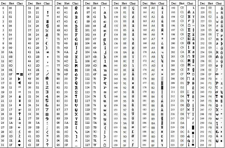
GLCD Controlling Constants
The GCBASIC constants for control of fonts and characters are shown in the table below.
| Constants | Controls | Options |
|---|---|---|
|
Words |
Explaination |
|
Words |
Explaination |
For more help, see GLCDCLS, GLCDDrawChar
e-Paper Controllers
This section covers GLCD devices known as e-Papers.
An e-paper device is a Microencapsulated Electrophoretic Display, MED.
A MED display uses tiny spheres, in which the charged color pigments are suspending in the transparent oil and would move depending on the electronic charge. The e-paper screen display patterns by reflecting the ambient light, so it has no background light requirement. Under sunshine, the e-paper screen still has high visibility with a wide viewing angle of 180 degree. It is the ideal choice for e-reading or providing information that can be refeshed at a slow rate of change.
GLCD Support for e-Papers
GCBASIC supports covers the full range of GLCD capabilities like line, circle, print.
GCBASIC supports SPI communications for the e-Papers - both hardware and software. And, GCBASIC suppors low memory configurations and SRAM for the display buffer.
See the demonstration programs to show you how to use these GCLD capabilities.
Memory Usage
The GCBASIC library uses RAM to buffer the e-paper display. The amount of RAM used is specific the the total pixel of the specific e-paper display. You can control to amount of RAM used as the buffer using the device specific constants, see below. Each device specific library has four memory options. Each of the memory options uses different amount RAM. The greater the amount of RAM used the faster the process of updating the e-paper display. Conversely, the smaller the amount of RAM used the slower the process of updating the e-paper display.
GLCD Page Transactions
To make the operation of the library seamless - the library supports GLCDTransaction. GLCDTransaction automatically manages the methods to update the e-paper via the buffer, where the buffer can be small. The process of transaction send GLCD commands to the e-paper display on a page and page basis. Each page is the size of the buffer and for a large e-paper display the number of pages may be equivilent to the numbers of pixels high (height).
GLCDTransaction simplies the operation by ensure the buffer is setup correctly, handles the GLCD appropiately, handles the sending of the buffer and then close out the process to update to the display.
To use GLCDTransaction use the followng two methods.
GLCD_Open_PageTransaction
....
glcd commands
.....
GLCD_Close_PageTransaction
It recommended to use GLCDTransactions at all times. These methods remove the complexity of the e-paper update process.
When using GLCDTransaction you must start the transaction with`GLCD_Open_PageTransaction` then include a series of GLCD commands and then terminate the transaction with GLCD_Close_PageTransaction.
GLCDTransaction Insight: When using GLCDtransactions the number of buffer pages is probably be greater then 1 (unless using the SRAM option), so the process of incrementing variables and calls to non-GLCD methods must be considered carefully. The transaction process will increment variables and call non-GLCD methods the same number of times as the number of pages. Therefore, design GLCDTransaction operations with this is mind.
SRAM as the e-paper buffer
To improve memory usage the e-paper the e-Paper libraries support the use of SRAM. SRAM can be used as an alternative to the microcontrollers RAM. Using SRAM does have a small performance impact but does free up the critical resource of the microcontroller RAM. The use of SRAM within the e-paper library is transparent to the user. To use SRAM as the e-paper buffer you will need to set-up the SRAM library. See the SRAM library for more details on SRAM usage.
When using SRAM for the e-paper buffer it is still remcommend to use GLCDTransaction as this ensure the SRAM buffer is correctly initialised.
Refresh mode
This library uses Full refresh: The e-Paper will flicker when full refreshing. This flicker removes the ghost image from the display. You could use Partial refresh as this doesnot flicker. Note that you cannot use Partial refresh all the time, you should full refresh e-paper regularly, otherwise, the ghost problem will get worse and even damage the display.
Refresh rate
When using the e-Paper library, you should set the update interval at least 180seconds, except when using Partial mode.
Please set the e-Paper to sleep mode in software or remove the power directly, otherwise, the e-Paper will be damaged because of working in high voltage for extendedtime periods. You need to update the content of the e-Paper at least once every 24 hours to avoid from burn-in problem.
Operating Voltages
The e-Paper should be driven with 3V3 operating voltages and signals.
If your Microcontroller (PIC, AVR and therefore an Arduino)cannot drive the e-Paper successfully. You must convert the level to 3.3V. The I/O level of Arduino is 5V. HEALTH WARNING:You can also try to connect the Vcc pin to the 5V of Arduino to see whether the e-Paper works, but we recommend you not to use 5V for a long time.
The e-Paper looks a little black or grey
You can try to change the value of Vcom the library by setting the VCOM_AND_DATA_INTERVAL constant. See the Vcom and data interval in the dataheet. VCOM_AND_DATA_INTERVAL can be 0x00 to 0x0F
GCBASIC library supports Black/White NOT Black/White/Red
The default is Black/White. To support Black/White/Red add `#define PANEL_SETTING_KWR 0x00`to you user program.
The constant are the TFT_BLACK and TFT_WHITE constants.
The e-paper has ghosting problem after working for some days
Please set the e-paper to sleep mode or disconnect it if you do not refresh the e-paper but need to power on your solution.
Do NOT leave power on for extended periods, otherwise, the voltage of panel remains high and it will damage the e-paper display.
e-Paper Guidelines
Remove power if practical.
ALWAYS use GLCDDisplay Off or sleep mode.
When in storage CLEAR the screen…. avoid burn it - use
GLCDCLD TFT_WHITE
GLCDDisplay Off
The recommended method is:
GLCDCLS TFT_WHITE
GLCDDisplay Off
do
loop
Using the e-Paper Library
To use the e-Paper driver for a specific simply include the following in your user code.
This will initialise the driver.
'Setup for the e-Paper
#include <glcd.h>
#define GLCD_TYPE GLCD_TYPE_EPD_EPD7in5
#define GLCD_EXTENDEDFONTSET1
#define GLCD_OLED_FONT
#define GLCD_TYPE_EPD7in5_LOWMEMORY4_GLCD_MODE fastest but uses a lot of RAM
'#define GLCD_TYPE_EPD7in5_LOWMEMORY3_GLCD_MODE
'#define GLCD_TYPE_EPD7in5_LOWMEMORY2_GLCD_MODE
'#define GLCD_TYPE_EPD7in5_LOWMEMORY1_GLCD_MODEslowest uses the least amount of RAM
'Pin mappings for SPI - this GLCD driver supports Hardware SPI and Software SPI
#define GLCD_DC portA.0 ' Data(hight)/ command(low) line
#define GLCD_CS portC.1 ' Chip select line (negate)
#define GLCD_RESETportD.2 ' Reset line (negate)
#define GLCD_DO portC.5 ' GLCD MOSI connect to MCU SDO
#define GLCD_SCKportC.3 ' Clock Line
#define GLCD_Busy portC.0 ' Busy Line
'The following should be used for hardware SPI remove or comment out if you want to use software SPI.
#define EPD_HardwareSPI
The GCBASIC constants for control display characteristics are shown in the table below.
| Constants | Controls | Options |
|---|---|---|
|
|
GLCD_TYPE_EPD_EPD7in5 and GLCD_TYPE_EPD_EPD2in13D supported |
|
Memory usage for the display buffer. Memory management is crutial when using the e-paper displays. |
or,
|
|
Specifies the output pin that is connected to Data/Command IO pin on the GLCD. |
Required |
|
Specifies the output pin that is connected to Chip Select (CS) on the GLCD. |
Required |
|
Specifies the output pin that is connected to Reset pin on the GLCD. |
Required |
|
Specifies the output pin that is connected to Data Out (GLCD in) pin on the GLCD. |
Required |
|
Specifies the output pin that is connected to Clock (CLK) pin on the GLCD. |
Required |
|
Specifies the output pin that is connected to Busy pin on the GLCD. |
Required |
|
Instructs the library to use hardware SPI, remove or comment out if you want to use software SPI. |
|
|
Specifies the speed of the SPI communications for Hardware SPI only. |
Optional defaults to MASTERFAST. Options are MASTERSLOW, |
The GCBASIC constants for control display characteristics are shown in the table below.
| Constants | Controls | Default |
|---|---|---|
|
The width parameter of the GLCD |
Specific to the e-Paper selected |
|
The height parameter of the GLCD |
Specific to the e-Paper selected |
|
Specifies the font width of the GCBASIC font set. |
|
The GCBASIC commands supported for this GLCD are shown in the table below. Always review the appropiate library for the latest full set of supported commands.
| Command | Purpose | Example |
|---|---|---|
|
Clear screen of GLCD |
|
|
Enables sleep mode, or, enables operations |
|
|
Print string of characters on GLCD using GCB font set |
|
|
Print character on GLCD using GCB font set |
|
|
Print characters on GLCD using GCB font set |
|
|
Draw a box on the GLCD to a specific size |
|
|
Draw a box on the GLCD to a specific size that is filled with the foreground colour. |
|
|
Draw a line on the GLCD to a specific length that is filled with the specific attribute. |
|
|
Set a pixel on the GLCD at a specific position that is set with the specific attribute. |
|
|
Commence a series of GLCD commands with memory buffer management. Must be followed a |
|
|
Terminate a series of GLCD commands. Must follow a |
|
Example Usage:
#chip mega328p, 16
#include <uno_mega328p.h>
#option explicit
'******************************************************************************************************
'Setup the E-Paper
#include <glcd.h>
#define HWSPIMode ULTRAFAST
#define GLCD_TYPE GLCD_TYPE_EPD_EPD2in13D
#define GLCD_EXTENDEDFONTSET1
#define GLCD_TYPE_EPD2in13D_LOWMEMORY4_GLCD_MODE
#define GLCD_OLED_FONT
#define GLCD_PROTECTOVERRUN
'Pin mappings for SPI - this GLCD driver supports Hardware SPI and Software SPI
#define GLCD_DC DIGITAL_9
#define GLCD_CS DIGITAL_10
#define GLCD_RESETDIGITAL_8
#define GLCD_DO DIGITAL_11
#define GLCD_SCKDIGITAL_13
#define GLCD_Busy DIGITAL_7
#define EPD_HARDWARESPI
'***********************************************************************************************
'Main program
GLCDForeground=TFT_BLACK
GLCDBackground=TFT_WHITE
GLCD_Open_PageTransaction
GLCDPrintStringLN ("GCBASIC")
GLCDPrintStringLN ("")
GLCDPrintStringLN ("Test of the e-Paper")
GLCDPrintStringLN ("")
GLCDPrintStringLN ("December 2021")
GLCD_Close_PageTransaction
GLCDDisplay Off
wait 2 s
GLCDDisplay On
GLCDCLS
GLCDDisplay off
do
loop
For more help, see GLCDCLS, GLCDDrawChar, GLCDPrint, GLCDReadByte, GLCDWriteByte, Pset or GLCDTransaction
Supported in <GLCD.H>
HX8347G Controllers
This section covers GLCD devices that use the HX8347G graphics controller.
HX8347G is a 262k-color single-chip SoC driver for a-TFT liquid crystal display with resolution of 240 RGB x 320 dots.
The HX8347-G is designed to provide a single-chip solution that combines a gate driver, a source driver, power supply circuit for 262k colors to drive a TFT panel with 240RGBx320 dots at maximum.
GCBASIC supports 65K-color mode operations.
The HX8347-G can be operated in low-voltage (1.4V) condition for the interface and integrated internal boosters that produce the liquid crystal voltage, breeder resistance and the voltage follower circuit for liquid crystal driver. In addition, The HX8347-G also supports various functions to reduce the power consumption of a LCD system via software control.
The GCBASIC constants shown below control the configuration of the HX8347G controller. The GCBASIC constants for control and data line connections are shown in the table below.
Connectivity is via an 8-bit bus. Where 8 pins are connected between the microcontroller and the GLCD to control the data bus plus 5 control pins. This is simple when using an Arduino GLCD Shield.
To use the HX8347G driver simply include the following in your user code. This will initialise the driver.
8-bit mode
'This GLCD driver supports 8 bit only. UNO ports can be replaced with porta.b constants.
#include <glcd.h>
#include <UNO_mega328p.h >
#define GLCD_TYPE GLCD_TYPE_HX8347
'Pin mappings for SPI - this GLCD driver supports Hardware SPI and Software SPI
#define GLCD_RD ANALOG_0 ' read command line
#define GLCD_WR ANALOG_1 ' write command line
#define GLCD_RS ANALOG_2 ' Command/Data line
#define GLCD_CS ANALOG_3 ' Chip select line
#define GLCD_RST ANALOG_4 ' Reset line
#define GLCD_DB0 DIGITAL_8
#define GLCD_DB1 DIGITAL_9
#define GLCD_DB2 DIGITAL_2
#define GLCD_DB3 DIGITAL_3
#define GLCD_DB4 DIGITAL_4
#define GLCD_DB5 DIGITAL_5
#define GLCD_DB6 DIGITAL_6
#define GLCD_DB7 DIGITAL_7
The GCBASIC constants for the interface to the controller are shown in the table below.
| Constants | Controls | Options |
|---|---|---|
|
|
|
|
Specifies the pin that is connected to DB0..7 IO pin on the GLCD (8 bit DBI). |
Required |
|
Specifies the output pin that is connected to Reset IO pin on the GLCD. |
Required |
|
Specifies the output pin that is connected to Chip Select (CS) on the GLCD. |
Required |
|
Specifies the output pin that is connected to Data/Command pin on the GLCD. |
Required |
|
Specifies the output pin that is connected to Data In (RW or WDR) pin on the GLCD. |
Required |
|
Specifies the output pin that is connected to Data Out (RD or RDR) pin on the GLCD. |
Required |
The GCBASIC constants for control display characteristics are shown in the table below.
| Constants | Controls | Default |
|---|---|---|
|
The width parameter of the GLCD |
|
|
The height parameter of the GLCD |
|
|
Specifies the font width of the GCBASIC font set. |
|
|
Specifies the use of the optional OLED font set. The GLCDfntDefaultsize can be set to 1 or 2 only.
|
Optional |
The GCBASIC commands supported for this GLCD are shown in the table below. Always review the appropiate library for the latest full set of supported commands.
| Command | Purpose | Example |
|---|---|---|
|
Clear screen of GLCD |
|
|
Print string of characters on GLCD using GCB font set |
|
|
Print character on GLCD using GCB font set |
|
|
Print characters on GLCD using GCB font set |
|
|
Draw a box on the GLCD to a specific size |
|
|
Draw a box on the GLCD to a specific size that is filled with the foreground colour. |
|
|
Draw a line on the GLCD to a specific length that is filled with the specific attribute. |
|
|
Set a pixel on the GLCD at a specific position that is set with the specific attribute. |
|
|
Set a byte value to the controller, see the datasheet for usage. |
|
|
Read a byte value from the controller, see the datasheet for usage. |
|
|
Rotate the display |
|
|
Specify color as a parameter for many GLCD commands |
Color constants for this device are shown in the list below. Any color can be defined using a valid hexidecimal word value between 0x0000 to 0xFFFF. |
HX8347G_BLACK 'hexidecimal value 0x0000
HX8347G_RED 'hexidecimal value 0xF800
HX8347G_GREEN 'hexidecimal value 0x0400
HX8347G_BLUE 'hexidecimal value 0x001F
HX8347G_WHITE 'hexidecimal value 0xFFFF
HX8347G_PURPLE 'hexidecimal value 0xF11F
HX8347G_YELLOW 'hexidecimal value 0xFFE0
HX8347G_CYAN 'hexidecimal value 0x07FF
HX8347G_D_GRAY 'hexidecimal value 0x528A
HX8347G_L_GRAY 'hexidecimal value 0x7997
HX8347G_SILVER 'hexidecimal value 0xC618
HX8347G_MAROON 'hexidecimal value 0x8000
HX8347G_OLIVE 'hexidecimal value 0x8400
HX8347G_LIME 'hexidecimal value 0x07E0
HX8347G_AQUA 'hexidecimal value 0x07FF
HX8347G_TEAL 'hexidecimal value 0x0410
HX8347G_NAVY 'hexidecimal value 0x0010
HX8347G_FUCHSIA 'hexidecimal value 0xF81F
These examples show how to drive a HX8347G based Graphic LCD module with the built in commands of GCBASIC. The 8 bit DBI example uses a UNO shield, this can easily adapted to Microchip architecture. The 16 bit DBI example uses a Mega2560 board.
Example:
#chip mega328p, 16
#option explicit
#include <glcd.h>
#include <UNO_mega328p.h >
#define GLCD_TYPE GLCD_TYPE_HX8347
#define GLCD_OLED_FONT
'Pin mappings for SPI - this GLCD driver supports Hardware SPI and Software SPI
#define GLCD_RD ANALOG_0 ' read command line
#define GLCD_WR ANALOG_1 ' write command line
#define GLCD_RS ANALOG_2 ' Command/Data line
#define GLCD_CS ANALOG_3 ' Chip select line
#define GLCD_RST ANALOG_4 ' Reset line
#define GLCD_DB0 DIGITAL_8
#define GLCD_DB1 DIGITAL_9
#define GLCD_DB2 DIGITAL_2
#define GLCD_DB3 DIGITAL_3
#define GLCD_DB4 DIGITAL_4
#define GLCD_DB5 DIGITAL_5
#define GLCD_DB6 DIGITAL_6
#define GLCD_DB7 DIGITAL_7
GLCDRotate ( Portrait )
GLCDCLS HX8347_RED
GLCDPrint(0, 0, "Test of the HX8347G Device")
end
For more help, see
GLCDCLS, GLCDDrawChar, GLCDPrint, GLCDReadByte, GLCDWriteByte or Pset
Supported in <GLCD.H>
ILI9326 Controllers
This section covers GLCD devices that use the ILI9326 graphics controller. The ILI9326 is a TFT LCD Single Chip Driver with 400RGBx320 Resolution and 262K colors.
GCBASIC supports 65K-color mode operations.
The GCBASIC constants shown below control the configuration of the ILI9326 controller. GCBASIC supports 8 bit bus connectivity - this is shown in the tables below.
To use the ILI9326 driver simply include the following in your user code. This will initialise the driver.
#include <glcd.h>
#DEFINE GLCD_TYPE GLCD_TYPE_ILI9326
'Pin mappings for ILI9326 - these MUST be specified
#define GLCD_RD porta.3 ' read command line
#define GLCD_WR porta.2 ' write command line
#define GLCD_RS porta.1 ' Command/Data line
#define GLCD_CS porta.0 ' Chip select line
#define GLCD_RST porta.5 ' Reset line
#define GLCD_DataPort portD
The GCBASIC constants for the interface to the controller are shown in the table below.
| Constants | Controls | Options |
|---|---|---|
|
|
|
|
Specifies the output pin that is connected to RD IO pin on the GLCD. |
Required |
|
Specifies the output pin that is connected to WR on the GLCD. |
Required |
|
Specifies the output pin that is connected to RS pin on the GLCD. |
Required |
|
Specifies the output pin that is connected to CS pin on the GLCD. |
Required |
|
Specifies the output pin that is connected to RST pin on the GLCD. |
Required |
|
Specifies the output port that is connected to DB0 to DB7 pins on the GLCD. |
Required |
The GCBASIC constants for control display characteristics are shown in the table below.
| Constants | Controls | Default |
|---|---|---|
|
The width parameter of the GLCD |
|
|
The height parameter of the GLCD |
|
|
Specifies the font width of the GCBASIC font set. |
|
|
Specifies the use of the optional OLED font set. The GLCDfntDefaultsize can be set to 1 or 2 only.
|
Optional |
The GCBASIC commands supported for this GLCD are shown in the table below. Always review the appropiate library for the latest full set of supported commands.
| Command | Purpose | Example |
|---|---|---|
|
Clear screen of GLCD |
|
|
Print string of characters on GLCD using GCB font set |
|
|
Print character on GLCD using GCB font set |
|
|
Print characters on GLCD using GCB font set |
|
|
Draw a box on the GLCD to a specific size |
|
|
Draw a box on the GLCD to a specific size that is filled with the foreground colour. |
|
|
Draw a line on the GLCD to a specific length that is filled with the specific attribute. |
|
|
Set a pixel on the GLCD at a specific position that is set with the specific attribute. |
|
|
Set a byte value to the controller, see the datasheet for usage. |
|
|
Read a byte value from the controller, see the datasheet for usage. |
|
|
Rotate the display |
|
|
Specify color as a parameter for many GLCD commands |
Color constants for this device are shown in the list below. |
ILI9326_BLACK 'hexidecimal value 0x0000
ILI9326_RED 'hexidecimal value 0xF800
ILI9326_GREEN 'hexidecimal value 0x07E0
ILI9326_BLUE 'hexidecimal value 0x001F
ILI9326_WHITE 'hexidecimal value 0xFFFF
ILI9326_PURPLE 'hexidecimal value 0xF11F
ILI9326_YELLOW 'hexidecimal value 0xFFE0
ILI9326_CYAN 'hexidecimal value 0x07FF
ILI9326_D_GRAY 'hexidecimal value 0x528A
ILI9326_L_GRAY 'hexidecimal value 0x7997
ILI9326_SILVER 'hexidecimal value 0xC618
ILI9326_MAROON 'hexidecimal value 0x8000
ILI9326_OLIVE 'hexidecimal value 0x8400
ILI9326_LIME 'hexidecimal value 0x07E0
ILI9326_AQUA 'hexidecimal value 0x07FF
ILI9326_TEAL 'hexidecimal value 0x0410
ILI9326_NAVY 'hexidecimal value 0x0010
ILI9326_FUCHSIA 'hexidecimal value 0xF81F
For a ILI9326 datasheet, please refer to Google.
This example shows how to drive a ILI9326 based Graphic LCD module with the built in commands of GCBASIC.
Example #1
;Chip Settings
#chip 16F1789,32
#config MCLRE=on
#option explicit
#include <glcd.h>
#define GLCD_TYPE GLCD_TYPE_ILI9326
#define GLCD_RD porta.3 ' read command line
#define GLCD_WR porta.2 ' write command line
#define GLCD_RS porta.1 ' Command/Data line
#define GLCD_CS porta.0 ' Chip select line
#define GLCD_RST porta.5 ' Reset line
#define GLCD_DataPort portD
GLCDPrint(0, 0, "Test of the ILI9326 Device")
end
Example #2
This example shows how to drive a ILI3941 with the OLED fonts. Note the use of the GLCDfntDefaultSize to select the size of the OLED font in use.
'Chip Settings
#chip 16F1789,32
#config MCLRE=on
#option explicit
#include <glcd.h>
#define GLCD_TYPE GLCD_TYPE_ILI9326
#define GLCD_RD porta.3 ' read command line
#define GLCD_WR porta.2 ' write command line
#define GLCD_RS porta.1 ' Command/Data line
#define GLCD_CS porta.0 ' Chip select line
#define GLCD_RST porta.5 ' Reset line
#define GLCD_DataPort portD
#define GLCD_OLED_FONT 'The constant is required to support OLED fonts
GLCDfntDefaultSize = 2
GLCDFontWidth = 5
GLCDPrint ( 40, 0, "OLED" )
GLCDPrint ( 0, 18, "Typ: ILI9326" )
GLCDPrint ( 0, 34, "Size: 400 x 240" )
GLCDfntDefaultSize = 1
GLCDPrint(20, 56,"https://goo.gl/gjrxkp")
For more help, see GLCDCLS, GLCDDrawChar, GLCDPrint, GLCDReadByte, GLCDWriteByte or Pset
Supported in <GLCD.H>
ILI9340 Controllers
This section covers GLCD devices that use the ILI9340 graphics controller. The ILI9340 is a TFT LCD Single Chip Driver with 240RGBx320 Resolution and 262K colors.
GCBASIC supports 65K-color mode operations.
The GCBASIC constants shown below control the configuration of the ILI9340 controller. GCBASIC supports SPI hardware and software connectivity - this is shown in the tables below.
To use the ILI9340 driver simply include the following in your user code. This will initialise the driver.
#include <glcd.h>
#DEFINE GLCD_TYPE GLCD_TYPE_ILI9340
'Pin mappings for ILI9340 - these MUST be specified
#define GLCD_DC porta.0 'example port setting
#define GLCD_CS porta.1 'example port setting
#define GLCD_RESET porta.2 'example port setting
#define GLCD_DI porta.3 'example port setting
#define GLCD_DO porta.4 'example port setting
The GCBASIC constants for the interface to the controller are shown in the table below.
| Constants | Controls | Options |
|---|---|---|
|
|
|
|
Specifies the output pin that is connected to Data/Command IO pin on the GLCD. |
Required |
|
Specifies the output pin that is connected to Chip Select (CS) on the GLCD. |
Required |
|
Specifies the output pin that is connected to Reset pin on the GLCD. |
Required |
|
Specifies the output pin that is connected to Data In (GLCD out) pin on the GLCD. |
Required |
|
Specifies the output pin that is connected to Data Out (GLCD in) pin on the GLCD. |
Required |
|
Specifies the output pin that is connected to Clock (CLK) pin on the GLCD. #define GLCD_SCK porta.5 'example port setting |
Required |
|
User can specify the hardware SPI mode. Must be one of MasterSlow, Master, Masterfast |
Optional. Defaults to Masterfast when chipMhz is less than 64mhz |
The GCBASIC constants for control display characteristics are shown in the table below.
| Constants | Controls | Default |
|---|---|---|
|
The width parameter of the GLCD |
|
|
The height parameter of the GLCD |
|
|
Specifies the font width of the GCBASIC font set. |
|
The GCBASIC commands supported for this GLCD are shown in the table below. Always review the appropiate library for the latest full set of supported commands.
| Command | Purpose | Example |
|---|---|---|
|
Clear screen of GLCD |
|
|
Print string of characters on GLCD using GCB font set |
|
|
Print character on GLCD using GCB font set |
|
|
Print characters on GLCD using GCB font set |
|
|
Draw a box on the GLCD to a specific size |
|
|
Draw a box on the GLCD to a specific size that is filled with the foreground colour. |
|
|
Draw a line on the GLCD to a specific length that is filled with the specific attribute. |
|
|
Set a pixel on the GLCD at a specific position that is set with the specific attribute. |
|
|
Set a byte value to the controller, see the datasheet for usage. |
|
|
Read a byte value from the controller, see the datasheet for usage. |
|
|
Rotate the display |
|
|
Specify color as a parameter for many GLCD commands |
Color constants for this device are shown in the list below. Any color can be defined using a valid hexidecimal word value between 0x0000 to 0xFFFF. |
ILI9340_BLACK 'hexidecimal value 0x0000
ILI9340_RED 'hexidecimal value 0xF800
ILI9340_GREEN 'hexidecimal value 0x07E0
ILI9340_BLUE 'hexidecimal value 0x001F
ILI9340_WHITE 'hexidecimal value 0xFFFF
ILI9340_PURPLE 'hexidecimal value 0xF11F
ILI9340_YELLOW 'hexidecimal value 0xFFE0
ILI9340_CYAN 'hexidecimal value 0x07FF
ILI9340_D_GRAY 'hexidecimal value 0x528A
ILI9340_L_GRAY 'hexidecimal value 0x7997
ILI9340_SILVER 'hexidecimal value 0xC618
ILI9340_MAROON 'hexidecimal value 0x8000
ILI9340_OLIVE 'hexidecimal value 0x8400
ILI9340_LIME 'hexidecimal value 0x07E0
ILI9340_AQUA 'hexidecimal value 0x07FF
ILI9340_TEAL 'hexidecimal value 0x0410
ILI9340_NAVY 'hexidecimal value 0x0010
ILI9340_FUCHSIA 'hexidecimal value 0xF81F
For a ILI9340 datasheet, please refer here.
This example shows how to drive a ILI9340 based Graphic LCD module with the built in commands of GCBASIC.
Example:
;Chip Settings
#chip 16F1937,32
#config MCLRE_ON 'microcontroller specific configuration
#include <glcd.h>
'Defines for ILI9340
#define GLCD_TYPE GLCD_TYPE_ILI9340
'Pin mappings for ILI9340
#define GLCD_DC porta.0
#define GLCD_CS porta.1
#define GLCD_RESET porta.2
#define GLCD_DI porta.3
#define GLCD_DO porta.4
#define GLCD_SCK porta.5
GLCDPrint(0, 0, "Test of the ILI9340 Device")
end
For more help, see GLCDCLS, GLCDDrawChar, GLCDPrint, GLCDReadByte, GLCDWriteByte or Pset
Supported in <GLCD.H>
ILI9341 Controllers
This section covers GLCD devices that use the ILI9341 graphics controller. The ILI9341 is a TFT LCD Single Chip Driver with 240RGBx320 Resolution and 262K colors.
GCBASIC supports 65K-color mode operations.
The GCBASIC supports different methods to controller the GLCD. These methods are shown below control the configuration of the ILI9341 controller. GCBASIC supports SPI hardware and software connectivity - this is shown in the tables below.
To use the ILI9341 driver simply include the following in your user code. This will initialise the driver of a SPI method of connection.
#include <glcd.h>
#DEFINE GLCD_TYPE GLCD_TYPE_ILI9341
'Pin mappings for ILI9341 - these MUST be specified
#define GLCD_DC porta.0 'example port setting
#define GLCD_CS porta.1 'example port setting
#define GLCD_RESET porta.2 'example port setting
#define GLCD_DI porta.3 'example port setting
#define GLCD_DO porta.4 'example port setting
#define GLCD_SCK porta.5 'example port setting
The GCBASIC constants for the interface to the controller are shown in the table below.
| Constants | Controls | Options |
|---|---|---|
|
|
Define the constant only |
SPI Method The method can use hardware or software SPI |
||
|
Specifies the output pin that is connected to Data/Command IO pin on the GLCD. |
Required |
|
Specifies the output pin that is connected to Chip Select (CS) on the GLCD. |
Required |
|
Specifies the output pin that is connected to Reset pin on the GLCD. |
Required |
|
Specifies the output pin that is connected to Data In (GLCD out) pin on the GLCD. If using hardware SPI this must be the hardware SPI port. |
Required |
|
Specifies the output pin that is connected to Data Out (GLCD in) pin on the GLCD. If using hardware SPI this must be the hardware SPI port. |
Required |
|
Specifies the output pin that is connected to Clock (CLK) pin on the GLCD. If using hardware SPI this must be the hardware SPI port. |
Required |
UNO Shield Method The method uses the ILI9341 attached via the UNO shield |
||
|
Specifies the output pin that is connected to Chip Select (CS) on the GLCD. |
Required |
|
Specifies the output pin that is connected to Reset pin on the GLCD. |
Required |
|
Specifies the output pin that is connected to Read (RD) pin on the GLCD. |
Required |
|
Specifies the output pin that is connected to Write (WR) pin on the GLCD. |
Required |
|
Specifies the output pin that is connected to Data/Command (RS) pin on the GLCD. |
Required |
|
DIGITAL_8 |
Mandated to this port |
|
DIGITAL_9 |
Mandated to this port |
|
DIGITAL_2 |
Mandated to this port |
|
DIGITAL_3 |
Mandated to this port |
|
DIGITAL_4 |
Mandated to this port |
|
DIGITAL_5 |
Mandated to this port |
|
DIGITAL_6 |
Mandated to this port |
|
DIGITAL_7 |
Mandated to this port |
8Bit Port Method The method uses a contigous 8bit port for the data port. |
||
|
Specifies the output pin that is connected to Chip Select (CS) on the GLCD. |
Required |
|
Specifies the output pin that is connected to Reset pin on the GLCD. |
Required |
|
Specifies the output pin that is connected to Read (RD) pin on the GLCD. |
Required |
|
Specifies the output pin that is connected to Write (WR) pin on the GLCD. |
Required |
|
Specifies the output pin that is connected to Data/Command (RS) pin on the GLCD. |
Required |
|
Any valid 8 bit port, like PORTC |
Required |
SPI Controls |
||
|
Specifies the speed of the SPI communications for Hardware SPI only. |
Optional defaults to MASTERFAST. Options are MASTERSLOW, |
The GCBASIC constants for control display characteristics are shown in the table below.
| Constants | Controls | Default |
|---|---|---|
|
The width parameter of the GLCD |
|
|
The height parameter of the GLCD |
|
|
Specifies the font width of the GCBASIC font set. |
|
|
Specifies the use of the optional OLED font set. The GLCDfntDefaultsize can be set to 1 or 2 only.
|
Optional |
The GCBASIC commands supported for this GLCD are shown in the table below. Always review the appropiate library for the latest full set of supported commands.
| Command | Purpose | Example |
|---|---|---|
|
Clear screen of GLCD |
|
|
Print string of characters on GLCD using GCB font set |
|
|
Print character on GLCD using GCB font set |
|
|
Print characters on GLCD using GCB font set |
|
|
Draw a box on the GLCD to a specific size |
|
|
Draw a box on the GLCD to a specific size that is filled with the foreground colour. |
|
|
Draw a line on the GLCD to a specific length that is filled with the specific attribute. |
|
|
Set a pixel on the GLCD at a specific position that is set with the specific attribute. |
|
|
Set a byte value to the controller, see the datasheet for usage. |
|
|
Read a byte value from the controller, see the datasheet for usage. |
|
|
Rotate the display |
|
|
Specify color as a parameter for many GLCD commands |
Color constants for this device are shown in the list below. |
|
Read the pixel color at the specified XY coordination. Returns long variable with Red, Green and Blue encoded in the lower 24 bits. |
ReadPixel( Xosition , Yposition ) or ReadPixel_ILI9341( Xosition , Yposition ) Any color can be defined using a valid hexidecimal word value between 0x0000 to 0xFFFF. |
ILI9341_BLACK 'hexidecimal value 0x0000
ILI9341_RED 'hexidecimal value 0xF800
ILI9341_GREEN 'hexidecimal value 0x07E0
ILI9341_BLUE 'hexidecimal value 0x001F
ILI9341_WHITE 'hexidecimal value 0xFFFF
ILI9341_PURPLE 'hexidecimal value 0xF11F
ILI9341_YELLOW 'hexidecimal value 0xFFE0
ILI9341_CYAN 'hexidecimal value 0x07FF
ILI9341_D_GRAY 'hexidecimal value 0x528A
ILI9341_L_GRAY 'hexidecimal value 0x7997
ILI9341_SILVER 'hexidecimal value 0xC618
ILI9341_MAROON 'hexidecimal value 0x8000
ILI9341_OLIVE 'hexidecimal value 0x8400
ILI9341_LIME 'hexidecimal value 0x07E0
ILI9341_AQUA 'hexidecimal value 0x07FF
ILI9341_TEAL 'hexidecimal value 0x0410
ILI9341_NAVY 'hexidecimal value 0x0010
ILI9341_FUCHSIA 'hexidecimal value 0xF81F
For a ILI9341 datasheet, please refer here.
This example shows how to drive a ILI9341 based Graphic LCD module with the built in commands of GCBASIC.
Example #1
;Chip Settings
#chip 16F1937,32
#config MCLRE_ON 'microcontroller specific configuration
#include <glcd.h>
'Defines for ILI9341
#define GLCD_TYPE GLCD_TYPE_ILI9341
'Pin mappings for ILI9341
#define GLCD_DC porta.0
#define GLCD_CS porta.1
#define GLCD_RESET porta.2
#define GLCD_DI porta.3
#define GLCD_DO porta.4
#define GLCD_SCK porta.5
GLCDPrint(0, 0, "Test of the ILI9341 Device")
end
Example #2
This example shows how to drive a ILI3941 with the OLED fonts. Note the use of the GLCDfntDefaultSize to select the size of the OLED font in use.
#define GLCD_OLED_FONT 'The constant is required to support OLED fonts
GLCDfntDefaultSize = 2
GLCDFontWidth = 5
GLCDPrint ( 40, 0, "OLED" )
GLCDPrint ( 0, 18, "Typ: ILI9341" )
GLCDPrint ( 0, 34, "Size: 320 x 240" )
GLCDfntDefaultSize = 1
GLCDPrint(20, 56,"https://goo.gl/gjrxkp")
Example #2 This example shows how to disable the large OLED Fontset. This disables the font to reduce memory usage.
When the extended OLED fontset is disabled every character will be shown as a block character.
#define GLCD_OLED_FONT 'The constant is required to support OLED fonts
#define GLCD_Disable_OLED_FONT2 'The constant to disable the extended OLED fontset.
GLCDfntDefaultSize = 2
GLCDFontWidth = 5
GLCDPrint ( 40, 0, "OLED" )
GLCDPrint ( 0, 18, "Typ: ILI9341" )
GLCDPrint ( 0, 34, "Size: 320 x 240" )
GLCDfntDefaultSize = 1
GLCDPrint(20, 56,"https://goo.gl/gjrxkp")
For more help, see GLCDCLS, GLCDDrawChar, GLCDPrint, GLCDReadByte, GLCDWriteByte or Pset
Supported in <GLCD.H>
ILI9481 Controllers
This section covers GLCD devices that use the ILI9481 graphics controller.
ILI9481 is a 262k-color single-chip SoC driver for a-TFT liquid crystal display with resolution of 320 RGB x 480 dots, comprising a 960-channel source driver, a 480-channel gate driver, 345,600 bytes GRAM for graphic data.
GCBASIC supports 65K-color mode operations.
The GCBASIC constants shown below control the configuration of the ILI9481controller. The GCBASIC constants for control and data line connections are shown in the table below. Two options are available for connectivity:
1) The 8-bit mode where 8 pins are connected between the microcontroller and the GLCD to control the data bus.
2) The 16-bit mode where two data ports (8 pins each) are connected between the microcontroller and the GLCD to control the data bus.
To use the ILI9481 driver simply include the following in your user code. This will initialise the driver.
8-bit mode
'Pin mappings for Data Bus Interface (DBI)
'this GLCD driver supports 8 bit and 16 bit parallel data lines
'8 bit DBI
#include <glcd.h>
#DEFINE GLCD_TYPE GLCD_TYPE_ILI9481
'8 bit control and parallel data lines (UNO Board)
#define GLCD_RD ANALOG_0 ' read command line
#define GLCD_WR ANALOG_1 ' write command line
#define GLCD_RS ANALOG_2 ' Command/Data line
#define GLCD_CS ANALOG_3 ' Chip select line
#define GLCD_RST ANALOG_4 ' Reset line
#define GLCD_DB0 DIGITAL_8 'Data port'
#define GLCD_DB1 DIGITAL_9 'Data port'
#define GLCD_DB2 DIGITAL_2 'Data port'
#define GLCD_DB3 DIGITAL_3 'Data port'
#define GLCD_DB4 DIGITAL_4 'Data port'
#define GLCD_DB5 DIGITAL_5 'Data port'
#define GLCD_DB6 DIGITAL_6 'Data port'
#define GLCD_DB7 DIGITAL_7 'Data port'
16-bit mode
'16 bit DBI
#include <glcd.h>
#define GLCD_TYPE GLCD_TYPE_ILI9481
#define GLCD_ILI9481_16bit
'16 bit control and dual data port lines (Mega2560 Board)
#define ILI9481_GLCD_CS PortG.1 'Chip Select line
#define ILI9481_GLCD_RS PortD.7 'DC data command line
#define ILI9481_GLCD_WR PortG.2 'Write command line
#define ILI9481_GLCD_RST PortG.0 'Reset line
#define ILI9481_DataPortH PortA 'DB[15:8]
#define ILI9481_DataPortL PortC 'DB[7:0]
The GCBASIC constants for the interface to the controller are shown in the table below.
| Constants | Controls | Options |
|---|---|---|
|
|
|
|
Specifies 16 bit DBI mode |
|
|
Specifies the pin that is connected to DB0..7 IO pin on the GLCD (8 bit DBI). |
Required |
|
Specifies the port DB[15:8] pins on the GLCD (16 bit DBI). |
Required |
|
Specifies the port DB[7:0] pins on the GLCD (16 bit DBI). |
Required |
|
Specifies the output pin that is connected to Reset IO pin on the GLCD. |
Required |
|
Specifies the output pin that is connected to Chip Select (CS) on the GLCD. |
Required |
|
Specifies the output pin that is connected to Data/Command pin on the GLCD. |
Required |
|
Specifies the output pin that is connected to Data In (RW or WDR) pin on the GLCD. |
Required |
|
Specifies the output pin that is connected to Data Out (RD or RDR) pin on the GLCD. |
Required |
The GCBASIC constants for control display characteristics are shown in the table below.
| Constants | Controls | Default |
|---|---|---|
|
The width parameter of the GLCD |
|
|
The height parameter of the GLCD |
|
|
Specifies the font width of the GCBASIC font set. |
|
The GCBASIC commands supported for this GLCD are shown in the table below. Always review the appropiate library for the latest full set of supported commands.
| Command | Purpose | Example |
|---|---|---|
|
Clear screen of GLCD |
|
|
Print string of characters on GLCD using GCB font set |
|
|
Print character on GLCD using GCB font set |
|
|
Print characters on GLCD using GCB font set |
|
|
Draw a box on the GLCD to a specific size |
|
|
Draw a box on the GLCD to a specific size that is filled with the foreground colour. |
|
|
Draw a line on the GLCD to a specific length that is filled with the specific attribute. |
|
|
Set a pixel on the GLCD at a specific position that is set with the specific attribute. |
|
|
Set a byte value to the controller, see the datasheet for usage. |
|
|
Read a byte value from the controller, see the datasheet for usage. |
|
|
Rotate the display |
|
|
Specify color as a parameter for many GLCD commands |
Color constants for this device are shown in the list below. Any color can be defined using a valid hexidecimal word value between 0x0000 to 0xFFFF. |
ILI9481_BLACK 'hexidecimal value 0x0000
ILI9481_RED 'hexidecimal value 0xF800
ILI9481_GREEN 'hexidecimal value 0x0400
ILI9481_BLUE 'hexidecimal value 0x001F
ILI9481_WHITE 'hexidecimal value 0xFFFF
ILI9481_PURPLE 'hexidecimal value 0xF11F
ILI9481_YELLOW 'hexidecimal value 0xFFE0
ILI9481_CYAN 'hexidecimal value 0x07FF
ILI9481_D_GRAY 'hexidecimal value 0x528A
ILI9481_L_GRAY 'hexidecimal value 0x7997
ILI9481_SILVER 'hexidecimal value 0xC618
ILI9481_MAROON 'hexidecimal value 0x8000
ILI9481_OLIVE 'hexidecimal value 0x8400
ILI9481_LIME 'hexidecimal value 0x07E0
ILI9481_AQUA 'hexidecimal value 0x07FF
ILI9481_TEAL 'hexidecimal value 0x0410
ILI9481_NAVY 'hexidecimal value 0x0010
ILI9481_FUCHSIA 'hexidecimal value 0xF81F
These examples show how to drive a ILI9481 based Graphic LCD module with the built in commands of GCBASIC. The 8 bit DBI example uses a UNO shield, this can easily adapted to Microchip architecture. The 16 bit DBI example uses a Mega2560 board.
Examples:
'8 bit DBI
#include <glcd.h>
#include <UNO_mega328p.h >
#define GLCD_TYPE GLCD_TYPE_ILI9481
'Pin mappings for SPI - this GLCD driver supports Hardware SPI and Software SPI
#define GLCD_RD ANALOG_0 ' read command line
#define GLCD_WR ANALOG_1 ' write command line
#define GLCD_RS ANALOG_2 ' Command/Data line
#define GLCD_CS ANALOG_3 ' Chip select line
#define GLCD_RST ANALOG_4 ' Reset line
#define GLCD_DB0 DIGITAL_8
#define GLCD_DB1 DIGITAL_9
#define GLCD_DB2 DIGITAL_2
#define GLCD_DB3 DIGITAL_3
#define GLCD_DB4 DIGITAL_4
#define GLCD_DB5 DIGITAL_5
#define GLCD_DB6 DIGITAL_6
#define GLCD_DB7 DIGITAL_7
GLCDPrint(0, 0, "Test of the ILI9481 Device")
end
'16 bit DBI
#chip mega2560, 16
#include <glcd.h>
#define GLCD_TYPE GLCD_TYPE_ILI9481
#define GLCD_ILI9481_16bit
#define ILI9481_GLCD_CS PortG.1
#define ILI9481_GLCD_RS PortD.7
#define ILI9481_GLCD_WR PortG.2
#define ILI9481_GLCD_RST PortG.0
#define ILI9481_DataPortH PortA
#define ILI9481_DataPortL PortC
#define ILI9481_YELLOW1 0xFFC1
#define ILI9481_BlueViolet 0x895C
GLCDCLS_ILI9481 ILI9481_Black
wait 1 s
GLCDCLS_ILI9481 ILI9481_White
wait 1 s
GLCDfntDefaultsize = 3
GLCDBackground = ILI9481_BlueViolet
GLCDForeground = ILI9481_Yellow1
GLCDCLS
wait 1 s
Start:
'demonstrate screen rotation
GLCDRotate (Portrait)
GLCDCLS
GLCDDrawString ( ILI9481_GLCD_WIDTH/2 - 24, ILI9481_GLCD_HEIGHT/2 - 62, "GCB")
GLCDDrawString ( ILI9481_GLCD_WIDTH/2 - 120, ILI9481_GLCD_HEIGHT/2 - 24, "ILI9481 Driver")
wait 5 s
GLCDRotate (Landscape)
GLCDCLS
GLCDDrawString ( ILI9481_GLCD_WIDTH/2 - 24, ILI9481_GLCD_HEIGHT/2 - 62, "GCB")
GLCDDrawString ( ILI9481_GLCD_WIDTH/2 - 120, ILI9481_GLCD_HEIGHT/2 -24, "ILI9481 Driver")
wait 5 s
GLCDRotate (Portrait_REV)
GLCDCLS
GLCDDrawString ( ILI9481_GLCD_WIDTH/2 - 24, ILI9481_GLCD_HEIGHT/2 - 62, "GCB")
GLCDDrawString ( ILI9481_GLCD_WIDTH/2 - 120, ILI9481_GLCD_HEIGHT/2 - 24, "ILI9481 Driver")
wait 5 s
GLCDRotate (Landscape_REV)
GLCDCLS
GLCDDrawString ( ILI9481_GLCD_WIDTH/2 - 24, ILI9481_GLCD_HEIGHT/2 - 62, "GCB")
GLCDDrawString ( ILI9481_GLCD_WIDTH/2 - 120, ILI9481_GLCD_HEIGHT/2 - 24, "ILI9481 Driver")
wait 5 s
goto Start
For more help, see
GLCDCLS, GLCDDrawChar, GLCDPrint, GLCDReadByte, GLCDWriteByte or Pset
Supported in <GLCD.H>
ILI9486(L) Controllers
This section covers GLCD devices that use the ILI9486(L) graphics controller.
The ILI9486(L) is a 262kcolor single-chip SoC driver for a-Si TFT liquid crystal display with resolution of 320RGBx480 dots, comprising a 960-channel source driver, a 480-channel gate driver, 345,600bytes GRAM for graphic data of 320RGBx480 dots.
The GCBASIC constants shown below control the configuration of the ILI9486(L) controller. GCBASIC supports 1) SPI using the SPI hardware module, 2) software SPI, 3) UNO shields and 4) an 8bit port bus - this is detailed in the tables below.
GCBASIC supports 65K-color mode operations.
To use the ILI9486(L) driver simply include the following in your user code. This will initialise the driver.
#include <glcd.h>
#DEFINE GLCD_TYPE GLCD_TYPE_ILI9486L
The GCBASIC constants for the interface to the controller are shown in the table below.
| Constants | Controls | Options |
|---|---|---|
|
|
|
|
Specifies the output pin that is connected to Data/Command IO pin on the GLCD. |
Required |
|
Specifies the output pin that is connected to Chip Select (CS) on the GLCD. |
Required |
|
Specifies the output pin that is connected to Reset pin on the GLCD. |
Required |
|
Specifies the output pin that is connected to Data In (GLCD out) pin on the GLCD. |
Required |
|
Specifies the output pin that is connected to Data Out (GLCD in) pin on the GLCD. |
Required |
|
Specifies the output pin that is connected to Clock (CLK) pin on the GLCD. |
Required |
The GCBASIC constants for the communicaton protocol for the controller are shown in the table below.
Communications Constants |
Use | Comments |
|---|---|---|
|
Specifies that hardware SPI will be used |
SPI ports MUST be defined that match the SPI module for each specific microcontroller #define ILI9486L_HardwareSPI |
|
Specifies the speed of the SPI communications for Hardware SPI only. |
Optional defaults to MASTERFAST. Options are MASTERSLOW, |
|
Specifies that a UNO shield will be used |
The shield will use 13 ports. These ports are pre-defined by the shield. These ports must be specified. #define UNO_8bit_Shield |
|
Specifies that a full 8 port will be used |
The microcontroller will use 13 ports. These port is defined as 8 contigous bits. These control port and the data port must be specified. #define GLCD_DataPort portb |
The GCBASIC constants for control display characteristics are shown in the table below.
| Constants | Controls | Default |
|---|---|---|
|
The width parameter of the GLCD |
|
|
The height parameter of the GLCD |
|
|
Specifies the font width of the GCBASIC font set. |
|
The GCBASIC commands supported for this GLCD are shown in the table below. Always review the appropiate library for the latest full set of supported commands.
| Command | Purpose | Example |
|---|---|---|
|
Clear screen of GLCD |
|
|
Print string of characters on GLCD using GCB font set |
|
|
Print character on GLCD using GCB font set |
|
|
Print characters on GLCD using GCB font set |
|
|
Draw a box on the GLCD to a specific size |
|
|
Draw a box on the GLCD to a specific size that is filled with the foreground colour. |
|
|
Draw a line on the GLCD to a specific length that is filled with the specific attribute. |
|
|
Set a pixel on the GLCD at a specific position that is set with the specific attribute. |
|
|
Set a byte value to the controller, see the datasheet for usage. |
|
|
Read a byte value from the controller, see the datasheet for usage. |
|
|
Rotate the display |
|
|
Specify color as a parameter for many GLCD commands |
Color constants for this device are shown in the list below. Any color can be defined using a valid hexidecimal word value between 0x0000 to 0xFFFF. |
TFT_BLACK 'hexidecimal value 0x0000
TFT_RED 'hexidecimal value 0xF800
TFT_GREEN 'hexidecimal value 0x07E0
TFT_BLUE 'hexidecimal value 0x001F
TFT_WHITE 'hexidecimal value 0xFFFF
TFT_PURPLE 'hexidecimal value 0xF11F
TFT_YELLOW 'hexidecimal value 0xFFE0
TFT_CYAN 'hexidecimal value 0x07FF
TFT_D_GRAY 'hexidecimal value 0x528A
TFT_L_GRAY 'hexidecimal value 0x7997
TFT_SILVER 'hexidecimal value 0xC618
TFT_MAROON 'hexidecimal value 0x8000
TFT_OLIVE 'hexidecimal value 0x8400
TFT_LIME 'hexidecimal value 0x07E0
TFT_AQUA 'hexidecimal value 0x07FF
TFT_TEAL 'hexidecimal value 0x0410
TFT_NAVY 'hexidecimal value 0x0010
TFT_FUCHSIA 'hexidecimal value 0xF81F
For a ILI9486L datasheet, please refer to Google.
This example shows how to drive a ILI9486L based Graphic LCD module with the built in commands of GCBASIC.
Example:
#chip mega328p, 16
#option explicit
#include <glcd.h>
#include <UNO_mega328p.h >
#define GLCD_TYPE GLCD_TYPE_ILI9486L
'Pin mappings for SPI - this GLCD driver supports Hardware SPI and Software SPI
#define GLCD_DC DIGITAL_8 ' Data command line
#define GLCD_CS DIGITAL_10 ' Chip select line
#define GLCD_RST DIGITAL_9 ' Reset line
#define GLCD_DI DIGITAL_13 ' Data in | MISO
#define GLCD_DO DIGITAL_11 ' Data out | MOSI
#define GLCD_SCK DIGITAL_13 ' Clock Line
#define ILI9486L_HardwareSPI ' Remove/comment out if you want to use software SPI.
GLCDPrint(0, 0, "Test of the ILI9486L Device")
end
For more help, see GLCDCLS, GLCDDrawChar, GLCDPrint, GLCDReadByte, GLCDWriteByte or Pset
Supported in <GLCD.H>
ILI9488 Controllers
This section covers GLCD devices that use the ILI9488 graphics controller.
ILI9488 is a 262k-color single-chip SoC driver for a-TFT liquid crystal display with resolution of 320 x 240 resolution, 16.7M-color and with internal GRAM .
GCBASIC supports 65K-color mode operations.
The GCBASIC constants shown below control the configuration of the ILI9488 controller. The GCBASIC constants for control and data line connections are shown in the table below. Only SPI is available for connectivity:
To use the ILI9488 driver simply include the following in your user code. This will initialise the driver.
SPI mode
'Pin mappings for SPI
#include <glcd.h>
#DEFINE GLCD_TYPE GLCD_TYPE_ILI9488
#DEFINE GLCD_DC PORTB.3 ' Data command line
#DEFINE GLCD_CS PORTB.5 ' Chip select line
#DEFINE GLCD_RST PORTB.4 ' Reset line
#DEFINE GLCD_DI PORTB.2 ' Data in | MISO
#DEFINE GLCD_DO PORTB.0 ' Data out | MOSI
#DEFINE GLCD_SCK PORTB.1 ' Clock Line
The GCBASIC constants for the interface to the controller are shown in the table below.
| Constants | Controls | Options |
|---|---|---|
|
GLCD_TYPE_ILI9488 |
|
|
Specifies to use the microcontrollers SPI module. For PPS microcontrollers the libary assumes PPS for SPI has been configured. |
Optional |
|
Specifies the speed of the SPI communications. |
Optional |
|
Specifies the output pin that is connected to Reset IO pin on the GLCD. |
Required |
|
Specifies the output pin that is connected to Chip Select (CS) on the GLCD. |
Required |
|
Specifies the output pin that is connected to Data/Command pin on the GLCD. |
Required |
|
Specifies the output pin that is connected to Data In (RW or WDR) pin on the GLCD. |
Required |
|
Specifies the output pin that is connected to Data Out (RD or RDR) pin on the GLCD. |
Required |
|
Specifies the output pin that is connected to Clock pin on the GLCD. |
Required |
The GCBASIC constants for control display characteristics are shown in the table below.
| Constants | Controls | Default |
|---|---|---|
|
The width parameter of the GLCD |
|
|
The height parameter of the GLCD |
|
|
Specifies the font width of the GCBASIC font set. |
|
The GCBASIC commands supported for this GLCD are shown in the table below. Always review the appropiate library for the latest full set of supported commands.
| Command | Purpose | Example |
|---|---|---|
|
Clear screen of GLCD |
|
|
Print string of characters on GLCD using GCB font set |
|
|
Print character on GLCD using GCB font set |
|
|
Print characters on GLCD using GCB font set |
|
|
Draw a box on the GLCD to a specific size |
|
|
Draw a box on the GLCD to a specific size that is filled with the foreground colour. |
|
|
Draw a line on the GLCD to a specific length that is filled with the specific attribute. |
|
|
Set a pixel on the GLCD at a specific position that is set with the specific attribute. |
|
|
Rotate the display |
|
|
Specify color as a parameter for many GLCD commands |
Color constants for this device are shown in the list below, butm you can use the generic TFT color scheme. Any color can be defined using a valid hexidecimal word value between 0x0000 to 0xFFFF. |
ILI9488_TFT_BLACK //0x000000
ILI9488_TFT_RED //0xFC0000
ILI9488_TFT_GREEN //0x00FC00
ILI9488_TFT_BLUE //0x0000FC
ILI9488_TFT_WHITE //0xFFFFFF
ILI9488_TFT_CYAN //0x003F3F
ILI9488_TFT_DARKCYAN //0x00AFAF
ILI9488_TFT_DARKGREEN //0x002100
ILI9488_TFT_DARKGREY //0xAAAAAA
ILI9488_TFT_GREENYELLOW //0x93FC33
ILI9488_TFT_LIGHTGREY //0xC9C9C9
ILI9488_TFT_MAGENTA //0xCC00CC
ILI9488_TFT_MAROON //0x7E007E
ILI9488_TFT_NAVY //0x00003E
ILI9488_TFT_OLIVE //0x783E00
ILI9488_TFT_ORANGE //0xFC2900
ILI9488_TFT_PINK //0xFC000F
ILI9488_TFT_PURPLE //0xF01F9E
ILI9488_TFT_YELLOW //0xFC7E00
These examples show how to drive a ILI9488 based Graphic LCD module with the built in commands of GCBASIC.
Examples - PPS Enabled
#chip 18F26K83, 64
#option Explicit
'Generated by PIC PPS Tool for GCBASIC
#startup InitPPS, 85
#DEFINE PPSToolPart 18f26k83
Sub InitPPS
'Module: UART pin directions
Dir PORTC.7 Out ' Make TX1 pin an output
'Module: UART1
RC7PPS = 0x0013 'TX1 > RC7
#IFDEF ILI9488_HardwareSPI
UNLOCKPPS
'Module: SPI1
RB0PPS = 0x001F 'SDO1 > RB0
RB1PPS = 0x001E 'SCK1 > RB1
SPI1SCKPPS = 0x0009 'RB1 > SCK1 (bi-directional)
SPI1SDIPPS = 0x000A 'RB2 > SDI1
#ELSE
RB0PPS = 0
RB1PPS = 0
#ENDIF
End Sub
// Template comment at the end of the config file
#include <glcd.h>
#DEFINE GLCD_TYPE GLCD_TYPE_ILI9488
#DEFINE ILI9488_HARDWARESPI
#DEFINE HWSPIMODE MASTERFAST
#DEFINE GLCD_DC PORTB.3 ' Data command line
#DEFINE GLCD_CS PORTB.5 ' Chip select line
#DEFINE GLCD_RST PORTB.4 ' Reset line
#DEFINE GLCD_DI PORTB.2 ' Data in | MISO
#DEFINE GLCD_DO PORTB.0 ' Data out | MOSI
#DEFINE GLCD_SCK PORTB.1 ' Clock Line
'''********************************************************************************
'main program start here
// Set the background
#DEFINE DEFAULT_GLCDBACKGROUND TFT_WHITE
GLCDPrint 0, 0, "Test of the ILI9488 Device", TFT_BLACK
end
Examples - Legacy non PPS microcontroller
#chip 16F1939
#option Explicit
#include <glcd.h>
#DEFINE GLCD_TYPE GLCD_TYPE_ILI9488
#DEFINE GLCD_DC PORTB.3 ' Data command line
#DEFINE GLCD_CS PORTB.5 ' Chip select line
#DEFINE GLCD_RST PORTB.4 ' Reset line
#DEFINE GLCD_DI PORTB.2 ' Data in | MISO
#DEFINE GLCD_DO PORTB.0 ' Data out | MOSI
#DEFINE GLCD_SCK PORTB.1 ' Clock Line
'''********************************************************************************
'main program start here
// Set the background
#DEFINE DEFAULT_GLCDBACKGROUND TFT_WHITE
GLCDPrint 0, 0, "Test of the ILI9488 Device", TFT_BLACK
end
For more help, see
GLCDCLS, GLCDDrawChar, GLCDPrint, GLCDReadByte, GLCDWriteByte or Pset
Supported in <GLCD.H>
Developer Notes
The ILI9488 library implemented uses BRG color scheme which is different from other GLCD libraries.
The ILI9488 library implemented also uses 18bits for color definition where the color scheme is defined as shown below:
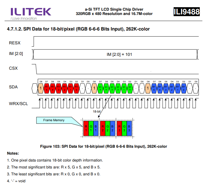
The ILI9488 library implemented there has the following differences from a typical GLCD library.
-
The colors are defined as RGB left justified 6 bits.
-
The colors are defined as Longs ( not Words other GLCDs are Words).
-
The color information uses a 18bit macro for SPI communications. Color information is sent to the GLCD in three bytes.
-
The color contraints are based on the SPI constraints specified in the ILI9488 datasheet.
KS0108 Controllers
This section covers GLCD devices that use the KS0108 graphics controller.
The KS0108 is an LCD is driven by on-board 5V parallel interface chipset KS0108 and KS0107. They are extremely common and well documented
The GCBASIC constants shown below control the configuration of the KS0108 controller. The only connectivity option is the 8-bit mode where 8 connections (for the data) are required between the microcontroller and the GLCD to control the data bus.
The KS0108 is a monochrome device.
To use the KS0108 driver simply include the following in your user code. This will initialise the driver.
#include <glcd.h>
#DEFINE GLCD_TYPE GLCD_TYPE_KS0108
#define GLCD_RW PORTB.1 'chip specific configuration
#define GLCD_RESET PORTB.5 'chip specific configuration
#define GLCD_CS1 PORTB.3 'chip specific configuration
#define GLCD_CS2 PORTB.4 'chip specific configuration
#define GLCD_RS PORTB.0 'chip specific configuration
#define GLCD_ENABLE PORTB.2 'chip specific configuration
#define GLCD_DB0 PORTC.7 'chip specific configuration
#define GLCD_DB1 PORTC.6 'chip specific configuration
#define GLCD_DB2 PORTC.5 'chip specific configuration
#define GLCD_DB3 PORTC.4 'chip specific configuration
#define GLCD_DB4 PORTC.3 'chip specific configuration
#define GLCD_DB5 PORTC.2 'chip specific configuration
#define GLCD_DB6 PORTC.1 'chip specific configuration
#define GLCD_DB7 PORTC.0 'chip specific configuration
The GCBASIC constants for the interface to the controller are shown in the table below.
| Constants | Controls | Options |
|---|---|---|
|
|
|
|
Specifies the output pin that is connected to Register Select on the GLCD. |
Required |
|
Specifies the output pin that is connected to Read/Write on the GLCD. The R/W pin can be disabled. |
Must be defined (unless R/W is disabled) |
|
Specifies the output pin that is connected to |
Required |
|
Specifies the output pin that is connected to |
Required |
|
Specifies the output pin that is connected to |
Required |
|
Specifies the output pin that is connected to |
Required |
|
Specifies the output pin that is connected to |
Required |
|
Specifies the output pin that is connected to |
Required |
|
Specifies the output pin that is connected to |
Required |
|
Specifies the output pin that is connected to |
Required |
|
Specifies the output pin that is connected to |
Required |
|
Specifies the output pin that is connected to |
Required |
|
Specifies the output pin that is connected to |
Required |
|
Disables read/write inspection of the device during read/write operations |
Optional, but recommend NOT to set.
The R/W pin can be disabled by setting the |
|
Not Available for this controller. |
Not applicable. |
The GCBASIC constants defined for the controller type are shown in the table below.
| Constants | Controls | Default |
|---|---|---|
|
The width parameter of the GLCD |
|
|
The height parameter of the GLCD |
|
|
Defining this will invert the Y Axis |
Not defined |
|
Read delay |
Default is 9 Can be set to improve overall performance. |
|
Write delay |
Default is 1 Can be set to improve performance. |
|
Clock Delay |
Default is 1 Can be set to improve performance. |
The GCBASIC constants for control display characteristics are shown in the table below.
| Variables | Controls | Default |
|---|---|---|
|
Width of the current GLCD font. |
Default is 6 pixels. |
|
Size of the current GLCD font. |
Default is 0. This equates to the standard GCB font set. |
|
Size of the current GLCD font. |
Default is 1. This equates to the 8 pixel high. |
The GCBASIC commands supported for this GLCD are shown in the table below.
| Command | Purpose | Example |
|---|---|---|
|
Clear screen of GLCD |
|
|
Print string of characters on GLCD using GCB font set |
|
|
Print character on GLCD using GCB font set |
|
|
Print characters on GLCD using GCB font set |
|
|
Draw a box on the GLCD to a specific size |
|
|
Draw a box on the GLCD to a specific size that is filled with the foreground colour. |
|
|
Draw a line on the GLCD to a specific length that is filled with the specific attribute. |
|
|
Turn the KS0108 On. The GLCD is On by default |
|
|
Turn the KS0108 Off. The GLCD is On by default |
|
Private methods |
||
|
Set a pixel on the GLCD at a specific position that is set with the specific attribute. |
|
|
Set a byte value to the controller, see the datasheet for usage. |
|
|
Read a byte value from the controller, see the datasheet for usage. |
|
For a KS0108 datasheet, please refer here.
This example shows how to drive a KS0108 based Graphic LCD module with the built in commands of GCBASIC. See Graphic LCD for details, this is an external web site.
;Chip Settings
#chip 16F886,16
'#config MCLRE = on 'enable reset switch on CHIPINO
#include <GLCD.h>
;Defines (Constants)
#define GLCD_RW PORTB.1 'D9 to pin 5 of LCD
#define GLCD_RESET PORTB.5 'D13 to pin 17 of LCD
#define GLCD_CS1 PORTB.3 'D12 to actually since CS1, CS2 can be reversed on some devices
#define GLCD_CS2 PORTB.4 'D11 to actually since CS1, CS2 can be reversed on some devices
#define GLCD_RS PORTB.0 'D8 to pin 4 D/I pin on LCD
#define GLCD_ENABLE PORTB.2 'D10 to Pin 6 on LCD
#define GLCD_DB0 PORTC.7 'D0 to pin 7 on LCD
#define GLCD_DB1 PORTC.6 'D1 to pin 8 on LCD
#define GLCD_DB2 PORTC.5 'D2 to pin 9 on LCD
#define GLCD_DB3 PORTC.4 'D3 to pin 10 on LCD
#define GLCD_DB4 PORTC.3 'D4 to pin 11 on LCD
#define GLCD_DB5 PORTC.2 'D5 to pin 12 on LCD
#define GLCD_DB6 PORTC.1 'D6 to pin 13 on LCD
#define GLCD_DB7 PORTC.0 'D7 to pin 14 on LCD
Do forever
GLCDCLS
GLCDPrint 0,10,"Hello" 'Print Hello
wait 5 s
GLCDPrint 0,10, "ASCII #:" 'Print ASCII #:
Box 18,30,28,40 'Draw Box Around ASCII Character
for char = 15 to 129 'Print 0 through 9
GLCDPrint 17, 20 , Str(char)+" "
GLCDdrawCHAR 20,30, char
wait 125 ms
next
line 0,50,127,50 'Draw Line using line command
for xvar = 0 to 80 'draw line using Pset command
pset xvar,63,on '
next '
Wait 1 s
GLCDPrint 0,10,"End " 'Print Hello
wait 1 s
Loop
For more help, see GLCDCLS, GLCDDrawChar, GLCDPrint, GLCDReadByte, GLCDWriteByte or Pset
Supported in <GLCD.H>
NEXTION Controllers
This section covers GLCD devices that use the serially attached Nextion graphics displays.
Nextion includes hardware part (a series of TFT boards) and software part (the Nextion editor (http://nextion.itead.cc/)).
The Nextion TFT board uses only one serial port to communicate. It lets you avoid the hassle of wiring. Nextion editor has mass components such as button, text, progress bar, slider, instrument panel etc. to enrich your interface design. And, the drag-and-drop function ensures that you spend less time in programming
The Nextion displays are 2.4 to 7.0 inches and range from 320*240 to 800*480 pixels. The connections are 5v, 0v, SerialIn and SerialOut. GCBASIC supports hardware and software serial connectivity.
See GITHUB for the set of GCBASIC demonstrations fro the Nextion displays. See Nextion demonstrations on GITHUB.
To use the Nextion driver simply include the following in your user code. This will initialise the driver.
Setup for Hardware Serial
' ----- Configuration
'Chip Settings.
#chip 16f18855,32
#option explicit
' ----- Set up the Nextion GLCD
#include <glcd.h>
#define GLCD_TYPE GLCD_TYPE_Nextion
;VERY IMPORTANT!!
;Change the width and height to match the rotation in the Nextion Editor
#define GLCD_WIDTH 320 'could be 320 | 400 | 272 | 480 but any valid dimension will work.
#define GLCD_HEIGHT 240 'could be 240 | 480 | 800 but any valid dimension will work.
;VERY IMPORTANT!!
;Fonts installed in the Nextion MUST match the fonts parameters loading to the GLCD.
;Obtain parameters from Nextion Editor/Font dialog.
#define NextionFont0 0, 8, 16 'Arial 8x16
#define NextionFont1 1, 12, 24 '24point 12x24 charset
#define NextionFont2 2, 16, 32 '32point 16x32 charset
' ----- End of set up for Nextion GLCD
' ----- Set up for Hardware Serial
;VERY IMPORTANT!!
;The Nextion MUST be setup for 9600 bps.
#define USART_BAUD_RATE 9600
#define USART_BLOCKING
;VERY IMPORTANT!!
;These two are optional. These constants are set in the library.
#define GLCD_NextionSerialPrint HSerPrint
#define GLCD_NextionSerialSend HSerSend
' ----- End of set up for Serial
'Generated by PIC PPS Tool for GCBASIC
'PPS Tool version: 0.0.5.11
'PinManager data: v1.55
'
'Template comment at the start of the config file
'
#startup InitPPS, 85
Sub InitPPS
'Module: EUSART
RXPPS = 0x0016 'RC6 > RX
'Module: EUSART
RC0PPS = 0x0010 'TX > RC0
TXPPS = 0x0010 'RC0 > TX (bi-directional)
RC5PPS = 0x0010 'TX > RC5
TXPPS = 0x0015 'RC5 > TX (bi-directional)
End Sub
'Template comment at the end of the config file
' ----- Main program starts
....
Setup for Software Serial
' ----- Configuration
'Chip Settings.
#chip 16f18855,32
#option explicit
' ----- Set up the Nextion GLCD
#include <glcd.h>
#define GLCD_TYPE GLCD_TYPE_Nextion
;VERY IMPORTANT!!
;Change the width and height to match the rotation in the Nextion Editor
#define GLCD_WIDTH 320 'could be 320 | 400 | 272 | 480 but any valid dimension will work.
#define GLCD_HEIGHT 240 'could be 240 | 480 | 800 but any valid dimension will work.
;VERY IMPORTANT!!
;Fonts installed in the Nextion MUST match the fonts parameters loading to the GLCD.
;Obtain parameters from Nextion Editor/Font dialog.
#define NextionFont0 0, 8, 16 'Arial 8x16
#define NextionFont1 1, 12, 24 '24point 12x24 charset
#define NextionFont2 2, 16, 32 '32point 16x32 charset
' ----- End of set up for Nextion GLCD
' ----- Set up for Software Serial - this is optional - shown to explain the method.
;Remove Hardware Serial before using Software serial
;You MUST also remove PPS setup, for hardware serial, when using Software serial
#include <SoftSerial.h>
; ----- Config Serial UART for sending:
#define SER1_BAUD 9600 ; baudrate must be defined
#define SER1_TXPORT PORTC ; I/O port (without .bit) must be defined
#define SER1_TXPIN 5 ; portbit must be defined
;VERY IMPORTANT!!
;These two constants are required to support the the library.
#define GLCD_NextionSerialPrint Ser1Print
#define GLCD_NextionSerialSend Ser1Send
'
' ----- End of set up for Serial
' ----- Main program starts
The GCBASIC constants shown below control the configuration of the Nextion controller. The GCBASIC constants for control and data line connections are shown in the table below.
| Constants | Controls | Options |
|---|---|---|
|
|
|
|
Default is |
Required |
|
Default is |
Required |
The GCBASIC constants for control display characteristics are shown in the table below.
| Constants | Controls | Default |
|---|---|---|
|
Mandated. The width parameter of the GLCD |
|
|
Mandated. The height parameter of the GLCD |
|
The GCBASIC Nextion specific commands supported for this GLCD are shown in the table below. Always review the appropiate library for the latest full set of supported commands.
| Command | Purpose | Example |
|---|---|---|
|
Print string of characters on GLCD using Nextion font set |
|
|
Locate the screen coordinates at a specific location. |
|
|
Print string of characters on GLCD using Nextion font set |
|
|
Print string of characters on GLCD using Nextion font set adding a newline and carriage return to move cursort to start of next line. |
|
|
Send the Nextion display a specific command and a specific value |
|
|
Update a Nextion display object with a specific value |
|
|
A function that returns a long, that can be treated as word variable, value of the Touch event.. As follows:
"tch1" for current y co-ordinate touched "tch2" for last x co-ordinate touched "tch3" for last y co-ordinate touched
1. Checks for three bytes of 0xFF. If Four 0xff are received then exit = non-block. 2. If at any time a 0x71 is recieved then we have data for the event. 3. If seven bytes arrive, but the method did not receive a 0x71 then exit = non-block. 4. The method supports software and hardware serial. As does all the other methods. 5. The method uses a function to receive the data not a sub-routine. 6. The method returns 0xBEEF if there is an invalid read, and, functional value for GLCDGetTouch_Nextion will also be set to 0xDEADBEEF |
myReturnedWordValue = GLCDGetTouch_Nextion( "tch2") or, myReturnedWordValue = GLCDGetTouch_Nextion( "tch3") |
The GCBASIC commonn commands supported for this GLCD are shown in the table below. Always review the appropiate library for the latest full set of supported commands.
| Command | Purpose | Example |
|---|---|---|
|
Clear screen of GLCD |
|
|
Print string of characters on GLCD using GCB font set |
|
|
Print character on GLCD using GCB font set |
|
|
Print characters on GLCD using GCB font set |
|
|
Draw a box on the GLCD to a specific size |
|
|
Draw a box on the GLCD to a specific size that is filled with the foreground colour. |
|
|
Draw a line on the GLCD to a specific length that is filled with the specific attribute. |
|
TFT_BLACK 'hexidecimal value 0x0000
TFT_RED 'hexidecimal value 0xF800
TFT_GREEN 'hexidecimal value 0x0400
TFT_BLUE 'hexidecimal value 0x001F
TFT_WHITE 'hexidecimal value 0xFFFF
TFT_PURPLE 'hexidecimal value 0xF11F
TFT_YELLOW 'hexidecimal value 0xFFE0
TFT_CYAN 'hexidecimal value 0x07FF
TFT_D_GRAY 'hexidecimal value 0x528A
TFT_L_GRAY 'hexidecimal value 0x7997
TFT_SILVER 'hexidecimal value 0xC618
TFT_MAROON 'hexidecimal value 0x8000
TFT_OLIVE 'hexidecimal value 0x8400
TFT_LIME 'hexidecimal value 0x07E0
TFT_AQUA 'hexidecimal value 0x07FF
TFT_TEAL 'hexidecimal value 0x0410
TFT_NAVY 'hexidecimal value 0x0010
TFT_FUCHSIA 'hexidecimal value 0xF81F
For more help, see
GLCDCLS
Supported in <GLCD.H>
NT7108C Controllers
This section covers GLCD devices that use the NT7108C graphics controller.
The NT7108C is an GLCD is driven by on-board 5V parallel interface chipset NT7108C. They are similar to the KS0108.
The GLCD controller is the Winstar WDG0151-TMI module, which is a 128×64 pixel monochromatic display.
It uses two Neotic display controller chips: NT7108C and NT7107C, which are similar with Samsung KS0108B and KS0107B controllers.
The controller uses a dot matrix LCD segment driver with 64 channel output, and therefore, the WDG0151 module contains two sets of it to drive 128 segments.
The GCBASIC constants shown below control the configuration of the NT7108C controller.
The connectivity options are as follows, This is required between the microcontroller and the GLCD to control the data bus.:
-
A full port mode. Where a full data port therefore eight contiguous port.bits. The port is used the data communications.
-
Eight port.bits mode. This option allows for greater flexibility with the configuration but will operate slower then the full port mode. These port.bits are used the data communications.
To use the NT7108C driver simply include the following in your user code. This will initialise the driver.
;Full port mode
#include <glcd.h>
#DEFINE GLCD_TYPE GLCD_TYPE_NT7108C
#define GLCD_DATA_PORT PORTD 'Data Port
#define GLCD_CS1 PORTC.1 'CS1 control line
#define GLCD_CS2 PORTC.0 'CS2 control line
#define GLCD_RS PORTe.0 'RS control line
#define GLCD_Enable PORTe.2 'Enable control line
#define GLCD_RW PORTc.3 'RW control line
#define GLCD_RESET PORTC.2 'Reset control line
or
;Eight port.bits mode
#include <glcd.h>
#DEFINE GLCD_TYPE GLCD_TYPE_NT7108C
;Defines (Constants)
;Define port as 8 port,bit(s)
#define GLCD_DB0 PORTA.2 'Data Port.bit 0
#define GLCD_DB1 PORTC.0 'Data Port.bit 1
#define GLCD_DB2 PORTC.1 'Data Port.bit 2
#define GLCD_DB3 PORTC.2 'Data Port.bit 3
#define GLCD_DB4 PORTB.4 'Data Port.bit 4
#define GLCD_DB5 PORTB.5 'Data Port.bit 5
#define GLCD_DB6 PORTB.6 'Data Port.bit 6
#define GLCD_DB7 PORTB.7 'Data Port.bit 7
;End of define as 8 port,bit(s)
#define GLCD_CS1 PORTC.7 'CS1 control line
#define GLCD_CS2 PORTC.6 'CS2 control line
#define GLCD_RS PORTC.5 'RS control line
#define GLCD_ENABLE PORTA.4 'Enable control line
#define GLCD_RW PORTC.4 'RW control line
#define GLCD_RESET PORTC.3 'Reset control line
The GCBASIC constants for the interface to the controller are shown in the table below.
| Constants | Controls | Options |
|---|---|---|
|
|
|
|
Specifies the output pin that is connected to Register Select on the GLCD. |
Required |
|
Specifies the output pin that is connected to Read/Write on the GLCD. |
Required |
|
Specifies the output pin that is connected to |
Required |
|
Specifies the output pin that is connected to |
Required |
|
Specifies the output pin that is connected to |
Required |
Full port mode |
||
|
Specifies the port that is connected to 8 connections on the GLCD. |
Required when using full port mode |
Eight port.bits mode |
||
|
Specifies the port.bit that is connected to a single connection on the GLCD. |
Required when using eight port.bits mode |
The GCBASIC constants defined for the controller type are shown in the table below. The NT7108C is very sensitive to clock timings. You may to adjust the clock timing to ensure the display operates correctly.
| Constants | Controls | Default |
|---|---|---|
|
The width parameter of the GLCD |
|
|
The height parameter of the GLCD |
|
|
Defining this will invert the Y Axis |
Not defined |
|
Read delay |
Default is 7 Can be set to improve overall performance. |
|
Write delay |
Default is 7 Can be set to improve performance. |
|
Clock Delay |
Default is 7 Can be set to improve performance. |
The GCBASIC constants for control display characteristics are shown in the table below.
| Variables | Controls | Default |
|---|---|---|
|
Width of the current GLCD font. |
Default is 6 pixels. |
|
Size of the current GLCD font. |
Default is 0. This equates to the standard GCB font set. |
|
Size of the current GLCD font. |
Default is 1. This equates to the 8 pixel high. |
The GCBASIC commands supported for this GLCD are shown in the table below.
| Command | Purpose | Example |
|---|---|---|
|
Clear screen of GLCD |
|
|
Print string of characters on GLCD using GCB font set |
|
|
Print character on GLCD using GCB font set |
|
|
Print characters on GLCD using GCB font set |
|
|
Draw a box on the GLCD to a specific size |
|
|
Draw a box on the GLCD to a specific size that is filled with the foreground colour. |
|
|
Draw a line on the GLCD to a specific length that is filled with the specific attribute. |
|
|
Set a pixel on the GLCD at a specific position that is set with the specific attribute. |
|
|
Set a byte value to the controller, see the datasheet for usage. |
|
|
Read a byte value from the controller, see the datasheet for usage. |
|
For a NT7108C datasheet, please refer here.
This example shows how to drive a NT7108C based Graphic LCD module with the built in commands of GCBASIC. See Graphic LCD for details, this is an external web site.
;Chip Settings #chip 16F1939,32 #option explicit #config MCLRE_On #include <glcd.h> #define GLCD_TYPE GLCD_TYPE_NT7108C ' Specify the GLCD type #define GLCDDirection 0 ' Flip the GLCD 0 do not flip, 1 flip 'Setup the device #define GLCD_CS1 PORTC.1 'D12 to actually since CS1, CS2 can be reversed on some devices #define GLCD_CS2 PORTC.0 #define GLCD_DATA_PORT PORTD #define GLCD_RS PORTe.0 #define GLCD_Enable PORTe.2 #define GLCD_RW PORTc.3 #define GLCD_RESET PORTC.2 GLCDPrint ( 4, 1, "GCBASIC 2021") ; Print some text Box 0, 0, 127, 10 Line 63, 10, 63, 63 Line 0, 37, 127, 37 Circle 63, 37, 15 End
For more help, see GLCDCLS, GLCDDrawChar, GLCDPrint, GLCDReadByte, GLCDWriteByte or Pset
Supported in <GLCD.H>
PCD8544 Controllers
This section covers GLCD devices that use the PCD844 graphics controller.
The PCD8544 is a low power CMOS LCD controller/driver, designed to drive a graphic display of 48 rows and 84 columns. All necessary functions for the display are provided in a single chip, including on-chip generation of LCD supply and bias voltages, resulting in a minimum of external components and low power consumption. The PCD8544 interfaces to microcontrollers through a serial bus interface.
The GCBASIC constants shown below control the configuration of the PCD844 controller. GCBASIC supports SPI software connectivity only - this is shown in the tables below.
The PCD8544 is a monochrome device.
The PCD844can operate in two modes. Full GLCD mode and Text/JPG mode the full GLCD mode requires a minimum of 512 bytes. For microcontrollers with limited memory the text only can be selected by setting the correct constant.
To use the PCD844 driver simply include the following in your user code. This will initialise the driver.
#include <glcd.h>
#define GLCD_TYPE GLCD_TYPE_PCD8544
' Pin mappings for software SPI for Nokia 3310 Device
#define GLCD_DO portc.5 'example port setting
#define GLCD_SCK portc.3 'example port setting
#define GLCD_DC portc.2 'example port setting
#define GLCD_CS portc.1 'example port setting
#define GLCD_RESET portc.0 'example port setting
The GCBASIC constants for the interface to the controller are shown in the table below.
| Constants | Controls | Options |
|---|---|---|
|
|
|
|
Specifies the output pin that is connected to Data/Command IO pin on the GLCD. |
Required |
|
Specifies the output pin that is connected to Chip Select (CS) on the GLCD. |
Required |
|
Specifies the output pin that is connected to Reset pin on the GLCD. |
Required |
|
Specifies the output pin that is connected to Data Out (GLCD in) pin on the GLCD. |
Required |
|
Specifies the output pin that is connected to Clock (CLK) pin on the GLCD. |
Required |
The GCBASIC constants for control display characteristics are shown in the table below.
| Constants | Controls | Default |
|---|---|---|
|
Specifies that the display controller will operate in text mode and BMP
draw mode only. |
Optional |
|
Specifies the clock delay, if required for slower microcontroller, |
Optional. Set to 0 as the default value |
|
Specifies the write delay, if required for slower microcontroller, |
Optional. Set to 0 as the default value |
|
The width parameter of the GLCD |
160 |
|
The height parameter of the GLCD |
128 |
|
Specifies the font width of the GCBASIC font set. |
6 |
The GCBASIC commands supported for this GLCD are shown in the table below. Always review the appropiate library for the latest full set of supported commands.
| Command | Purpose | Example |
|---|---|---|
|
Clear screen of GLCD |
|
|
Print string of characters on GLCD using GCB font set |
|
|
Print character on GLCD using GCB font set |
|
|
Print characters on GLCD using GCB font set |
|
|
Draw a box on the GLCD to a specific size |
|
|
Draw a box on the GLCD to a specific size that is filled with the foreground colour. |
|
|
Draw a line on the GLCD to a specific length that is filled with the specific attribute. |
|
|
Set a pixel on the GLCD at a specific position that is set with the specific attribute. |
|
|
Set a byte value to the controller, see the datasheet for usage. |
|
|
Read a byte value from the controller, see the datasheet for usage. |
|
*For a PCD8544 datasheet, please refer
here
This example shows how to drive a PCD8544 based Graphic LCD module with the built in commands of GCBASIC.
Example:
#chip 16lf1939,32
#option Explicit
#config MCLRE_ON
#include <glcd.h>
#DEFINE GLCD_TYPE GLCD_TYPE_PCD8544
' Pin mappings for software SPI for Nokia 3310 Device
#define GLCD_DO portc.5
#define GLCD_SCK portc.3
#define GLCD_DC portc.2
#define GLCD_CS portc.1
#define GLCD_RESET portc.0
Dim outString as string
Dim ccount, byteNumber as Byte
Dim longNumber as Long
Dim wordNumber as Word
GLCDCLS
DO forever
for CCount = 31 to 127
GLCDPrint (0, 0, "PrintStr")
GLCDDrawString (0, 9, "DrawStr")
GLCDPrint ( 44 , 21, " ")
GLCDPrint ( 44 , 29, " ") ' word value
GLCDPrint ( 44 , 37, " ") ' Byte value
outstring = hex( longNumber_U)
GLCDPrint ( 44 , 21,outstring )
outstring = hex( longNumber_H)
GLCDPrint ( 55 , 21, outstring)
outstring = hex( longNumber)
GLCDPrint ( 67 , 21, outstring )
GLCDPrint ( 44 , 29, mid( str(wordNumber),1, 6))
GLCDPrint ( 44 , 37, byteNumber)
box 46,9,57,19
GLCDDrawChar(48, 9, CCount )
outString = str( CCount )
' draw a box to overwrite existing strings
FilledBox(58,9,GLCD_WIDTH-1,17,GLCDBackground )
GLCDDrawString(58, 9, outString )
box 0,0,GLCD_WIDTH-1, GLCD_HEIGHT-1
box GLCD_WIDTH-5, GLCD_HEIGHT-5,GLCD_WIDTH- 1, GLCD_HEIGHT-1
filledbox 2,30,6,38, wordNumber
Circle( 25,30,8,1) ;center
FilledCircle( 25,30,4,longNumber xor 1) ;center
line 0, GLCD_HEIGHT-1 , GLCD_WIDTH/2, (GLCD_HEIGHT /2) +1
line GLCD_WIDTH/2, (GLCD_HEIGHT /2) +1 ,0, (GLCD_HEIGHT /2) +1
longNumber = longNumber + 7
wordNumber = wordNumber + 3
byteNumber++
NEXT
LOOP
end
For more help, see GLCDCLS, GLCDDrawChar, GLCDPrint, GLCDReadByte, GLCDWriteByte or Pset
Supported in <GLCD.H> and <glcd_PCD8544.h>
SDD1289 Controllers
This section covers GLCD devices that use the SDD1289 graphics controller. The SDD1289 is a 240 x 320 single chip controller driver IC for 262k color (RGB) amorphous TFT LCD.
The GCBASIC constants shown below control the configuration of the SDD1289 controller. GCBASIC supports SPI hardware and software connectivity - this is shown in the tables below.
GCBASIC supports 65K-color mode operations.
To use the SDD1289 driver simply include the following in your user code. This will initialise the driver.
#include <glcd.h>
#DEFINE GLCD_TYPE GLCD_TYPE_SDD1289
'Pin mappings for SDD1289
#define GLCD_DC porta.0 'example port setting
#define GLCD_CS porta.1 'example port setting
#define GLCD_RESET porta.2 'example port setting
#define GLCD_DI porta.3 'example port setting
#define GLCD_DO porta.4 'example port setting
#define GLCD_SCK porta.5 'example port setting
The GCBASIC constants for control display characteristics are shown in the table below.
| Constants | Controls | Default |
|---|---|---|
|
|
|
|
Specifies the output pin that is connected to Data/Command IO pin on the GLCD. |
Required |
|
Specifies the output pin that is connected to Chip Select (CS) on the GLCD. |
Required |
|
Specifies the output pin that is connected to Reset pin on the GLCD. |
Required |
|
Specifies the output pin that is connected to Data In (GLCD out) pin on the GLCD. |
Required |
|
Specifies the output pin that is connected to Data Out (GLCD in) pin on the GLCD. |
Required |
|
Specifies the output pin that is connected to Clock (CLK) pin on the GLCD. |
Required |
The GCBASIC constants for control display characteristics are shown in the table below.
| Constant | Purpose | Default |
|---|---|---|
|
The width parameter of the GLCD |
Set automatically |
|
The height parameter of the GLCD |
Set automatically |
|
Specifies the font width of the GCBASIC font set. |
6 |
The GCBASIC commands supported for this GLCD are shown in the table below. Always review the appropiate library for the latest full set of supported commands.
| Command | Purpose | Example |
|---|---|---|
|
Clear screen of GLCD |
|
|
Print string of characters on GLCD using GCB font set |
|
|
Print character on GLCD using GCB font set |
|
|
Print characters on GLCD using GCB font set |
|
|
Draw a box on the GLCD to a specific size |
|
|
Draw a box on the GLCD to a specific size that is filled with the foreground colour. |
|
|
Draw a line on the GLCD to a specific length that is filled with the specific attribute. |
|
|
Set a pixel on the GLCD at a specific position that is set with the specific attribute. |
|
|
Set a byte value to the controller, see the datasheet for usage. |
|
|
Read a byte value from the controller, see the datasheet for usage. |
|
|
Specify color as a parameter for many GLCD commands |
Color constants for this device are shown in the list below. Any color can be defined using a valid hexidecimal word value between 0x0000 to 0xFFFF. |
SSD1289_BLACK 'hexidecimal value 0x0000
SSD1289_RED 'hexidecimal value 0xF800
SSD1289_GREEN 'hexidecimal value 0x07E0
SSD1289_BLUE 'hexidecimal value 0x001F
SSD1289_WHITE 'hexidecimal value 0xFFFF
SSD1289_PURPLE 'hexidecimal value 0xF11F
SSD1289_YELLOW 'hexidecimal value 0xFFE0
SSD1289_CYAN 'hexidecimal value 0x07FF
SSD1289_D_GRAY 'hexidecimal value 0x528A
SSD1289_L_GRAY 'hexidecimal value 0x7997
SSD1289_SILVER 'hexidecimal value 0xC618
SSD1289_MAROON 'hexidecimal value 0x8000
SSD1289_OLIVE 'hexidecimal value 0x8400
SSD1289_LIME 'hexidecimal value 0x07E0
SSD1289_AQUA 'hexidecimal value 0x07FF
SSD1289_TEAL 'hexidecimal value 0x0410
SSD1289_NAVY 'hexidecimal value 0x0010
SSD1289_FUCHSIA 'hexidecimal value 0xF81F
For a SDD1289 datasheet, please refer here.
This example shows how to drive a SDD1289 based Graphic LCD module with the built in commands of GCBASIC.
Example:
;Chip Settings
#chip 16F1937,32
#config MCLRE_ON
#include <glcd.h>
'Defines for SDD1289
#define GLCD_TYPE GLCD_TYPE_SDD1289
'Pin mappings for SDD1289
#define GLCD_DC porta.0
#define GLCD_CS porta.1
#define GLCD_RESET porta.2
#define GLCD_DI porta.3
#define GLCD_DO porta.4
#define GLCD_SCK porta.5
GLCDPrint(0, 0, "Test of the SDD1289 Device")
end
For more help, see
GLCDCLS, GLCDDrawChar, GLCDPrint, GLCDReadByte, GLCDWriteByte OR Pset
Supported in <GLCD.H>
SH1106 Controllers
This section covers GLCD devices that use the SH1106 graphics controller. THe SH1106 is a single-chip CMOS OLED/PLED driver with controller for organic/polymer light emitting diode dot-matrix graphic display system. SH1106 consists of 132 segments, 64 commons that can support a maximum display resolution of 132 X 64. It is designed for Common Cathode type OLED panel.
The GCBASIC constants shown below control the configuration of the SH1106 controller. GCBASIC supports i2C hardware and software connectivity - this is shown in the tables below.
The SH1106 is a monochrome device.
To use the SH1106 driver simply include the following in your user code. This will initialise the driver. You can select Full Mode GLCD, Low Memory Mode GLCD or Text mode these require 1024, 128 or 0 byte GLCD buffer respectively - you microcontroller requires sufficient RAM to support the selected mode of GLCD operation.
Specific to the Rajguru Electronics 13002-Series display you can can specify a GLCD_SubType 13002 to enable support.
#include <glcd.h>
; ----- Define GLCD Hardware settings
#define GLCD_TYPE GLCD_TYPE_SH1106
#define GLCD_I2C_Address 0x78
'#define GLCD_TYPE_SH1106_LOWMEMORY_GLCD_MODE 'select Low Memory mode of operation
'#define GLCD_TYPE_SH1106_CHARACTER_MODE_ONLY 'select Text mode of operation
'#define GLCD_SubType 13002 'add to support Rajguru Electronics 13002-Series display
; ----- Define Hardware settings
' Define I2C settings
#define HI2C_BAUD_RATE 400
#define HI2C_DATA
HI2CMode Master
The GCBASIC constants for control display characteristics are shown in the table below.
| Constants | Controls | Options |
|---|---|---|
|
|
Required |
|
I2C address of the GLCD. |
Required |
|
|
400 or 100 |
|
|
Mandated, plus |
The GCBASIC constants for control display characteristics are shown in the table below.
| Constants | Controls | Default |
|---|---|---|
|
The width parameter of the GLCD |
|
|
The height parameter of the GLCD |
|
|
Specifies the font width of the GCBASIC font set. |
|
|
Specifies that the display controller will operate in text mode and BMP
draw mode only. |
Optional |
|
Specifies that the display controller will operate in Low Memory mode. |
Optional |
The GCBASIC commands supported for this GLCD are shown in the table below. Always review the appropiate library for the latest full set of supported commands.
| Command | Purpose | Example |
|---|---|---|
|
Clear screen of GLCD |
|
|
Print string of characters on GLCD using GCB font set |
|
|
Print character on GLCD using GCB font set |
|
|
Print characters on GLCD using GCB font set |
|
|
Draw a box on the GLCD to a specific size |
|
|
Draw a box on the GLCD to a specific size that is filled with the foreground colour. |
|
|
Draw a line on the GLCD to a specific length that is filled with the specific attribute. |
|
|
Set a pixel on the GLCD at a specific position that is set with the specific attribute. |
|
|
Set a byte value to the controller, see the datasheet for usage. |
|
|
Read a byte value from the controller, see the datasheet for usage. |
|
|
Commence a series of GLCD commands when in low memory mode. Must be followed a |
|
|
Commence a series of GLCD commands when in low memory mode. Must follow a |
The additional GCBASIC commands for this GLCD are shown in the table below.
| Command | Purpose |
|---|---|
|
Inverts the display |
|
Set the display to normal mode |
|
Sets the constrast between 0 and 255. The contrast increases as the value increases. |
For a SH1106 datasheet, please refer here.
This example shows how to drive a SH1106 based Graphic LCD module with the built in commands of GCBASIC.
; ----- Configuration
#chip mega328p,16
#include <glcd.h>
; ----- Define Hardware settings
' Define I2C settings
#define HI2C_BAUD_RATE 400
#define HI2C_DATA
HI2CMode Master
; ----- Define GLCD Hardware settings
#define GLCD_TYPE GLCD_TYPE_SH1106
#define GLCD_I2C_Address 0x78
GLCDCLS
GLCDPrint 0, 0, "GCBASIC"
GLCDPrint (0, 16, "Anobium 2021")
wait 3 s
GLCDCLS
' Prepare the static components of the screen
GLCDPrint ( 0, 0, "PrintStr") ; Print some text
GLCDPrint ( 64, 0, "@")
; Print some more text
GLCDPrint ( 72, 0, ChipMhz) ; Print chip speed
GLCDPrint ( 86, 0, "Mhz") ; Print some text
GLCDDrawString( 0,8,"DrawStr") ; Draw some text
box 0,0,GLCD_WIDTH-1, GLCD_HEIGHT-1 ; Draw a box
box GLCD_WIDTH-5, GLCD_HEIGHT-5,GLCD_WIDTH-1, GLCD_HEIGHT-1 ; Draw a box
Circle( 44,41,15) ; Draw a circle
line 64,31,0,31 ; Draw a line
DO forever
for CCount = 31 to 127
GLCDPrint ( 64 , 36, hex(longNumber_E ) ) ; Print a HEX string
GLCDPrint ( 76 , 36, hex(longNumber_U ) ) ; Print a HEX string
GLCDPrint ( 88 , 36, hex(longNumber_H ) ) ; Print a HEX string
GLCDPrint ( 100 , 36, hex(longNumber ) ) ; Print a HEX string
GLCDPrint ( 112 , 36, "h" ) ; Print a HEX string
GLCDPrint ( 64 , 44, pad(str(wordNumber), 5 ) ) ; Print a padded string
GLCDPrint ( 64 , 52, pad(str(byteNumber), 3 ) ) ; Print a padded string
box (46,9,56,19) ; Draw a Box
GLCDDrawChar(48, 9, CCount ) ; Draw a character
outString = str( CCount ) ; Prepare a string
GLCDDrawString(64, 9, pad(outString,3) ) ; Draw a string
filledbox 3,43,11,51, wordNumber ; Draw a filled box
FilledCircle( 44,41,9, longNumber xor 1) ; Draw a filled box
line 0,63,64,31 ; Draw a line
; Do some simple maths
longNumber = longNumber + 7 : wordNumber = wordNumber + 3 : byteNumber++
NEXT
LOOP
end
This example shows how to drive a SH1106 based Graphic I2C LCD module with the built in commands of GCBASIC using Low Memory Mode GLCD.
Note the use of GLCD_Open_PageTransaction and GLCD_Close_PageTransaction to support the Low Memory Mode of operation and the contraining of all GLCD commands with the transaction commands. The use Low Memory Mode GLCD the two defines GLCD_TYPE_SH1106_LOWMEMORY_GLCD_MODE and GLCD_TYPE_SH1106_CHARACTER_MODE_ONLY are included in the user program.
#chip mega328p,16
#include <glcd.h>
; ----- Define Hardware settings
' Define I2C settings
#define HI2C_BAUD_RATE 400
#define HI2C_DATA
HI2CMode Master
; ----- Define GLCD Hardware settings
#define GLCD_TYPE GLCD_TYPE_SH1106 'for 128 * 64 pixels support
#define GLCD_I2C_Address 0x78
#define GLCD_TYPE_SH1106_LOWMEMORY_GLCD_MODE
#define GLCD_TYPE_SH1106_CHARACTER_MODE_ONLY
dim outString as string * 21
GLCDCLS
GLCD_Open_PageTransaction 0,7
GLCDPrint 0, 0, "GCBASIC"
GLCDPrint (0, 16, "Anobium 2021")
GLCD_Close_PageTransaction
wait 3 s
GLCDCLS
DO forever
for CCount = 31 to 127
outString = str( CCount ) ; Prepare a string
GLCD_Open_PageTransaction 0,7
' Prepare the static components of the screen
GLCDPrint ( 0, 0, "PrintStr") ; Print some text
GLCDPrint ( 64, 0, "@")
; Print some more text
GLCDPrint ( 72, 0, ChipMhz) ; Print chip speed
GLCDPrint ( 86, 0, "Mhz") ; Print some text
GLCDDrawString( 0,8,"DrawStr") ; Draw some text
box 0,0,GLCD_WIDTH-1, GLCD_HEIGHT-1 ; Draw a box
box GLCD_WIDTH-5, GLCD_HEIGHT-5,GLCD_WIDTH-1, GLCD_HEIGHT-1 ; Draw a box
Circle( 44,41,15) ; Draw a circle
line 64,31,0,31 ; Draw a line
GLCDPrint ( 64 , 36, hex(longNumber_E ) ) ; Print a HEX string
GLCDPrint ( 76 , 36, hex(longNumber_U ) ) ; Print a HEX string
GLCDPrint ( 88 , 36, hex(longNumber_H ) ) ; Print a HEX string
GLCDPrint ( 100 , 36, hex(longNumber ) ) ; Print a HEX string
GLCDPrint ( 112 , 36, "h" ) ; Print a HEX string
GLCDPrint ( 64 , 44, pad(str(wordNumber), 5 ) ) ; Print a padded string
GLCDPrint ( 64 , 52, pad(str(byteNumber), 3 ) ) ; Print a padded string
box (46,8,56,19) ; Draw a Box
GLCDDrawChar(48, 9, CCount ) ; Draw a character
GLCDDrawString(64, 9, pad(outString,3) ) ; Draw a string
filledbox 3,43,11,51, wordNumber ; Draw a filled box
FilledCircle( 44,41,9, longNumber xor 1) ; Draw a filled box
line 0,63,64,31 ; Draw a line
GLCD_Close_PageTransaction
; Do some simple maths
longNumber = longNumber + 7 : wordNumber = wordNumber + 3 : byteNumber++
NEXT
LOOP
end
For more help, see GLCDCLS, GLCDDrawChar, GLCDPrint, GLCDReadByte, GLCDWriteByte or Pset
Supported in <GLCD.H>
SSD1306 Controllers
This section covers GLCD devices that use the SSD1306 graphics controller.
The SSD1306 is a single-chip CMOS OLED/PLED driver with controller for organic / polymer light emitting diode dot-matrix graphic display system. It consists of 128 segments and 64 commons. This IC is designed for Common Cathode type OLED panel.
The SSD1306 embeds with contrast control, display RAM and oscillator, which reduces the number of external components and power consumption. It has 256-step brightness control. Data/Commands are sent from general MCU through the hardware selectable 6800/8000 series compatible Parallel Interface, I2C interface or Serial Peripheral Interface. It is suitable for many compact portable applications, such as mobile phone sub-display, MP3 player and calculator, etc.
The GCBASIC constants shown below control the configuration of the SSD1306 controller. GCBASIC supports SPI and I2C hardware & software connectivity - this is shown in the tables below.
To use the SSD1306 driver simply include the following in your user code. This will initialise the driver.
The SSD1306 library supports 128 * 64 pixels or 128 * 32 pixels. The default is 128 * 64 pixels.
The SSD1306 is a monochrome device.
The SSD1306 can operate in three modes. Full GLCD mode, Low Memory GLCD mode or Text/JPG mode the full GLCD mode requires a minimum of 1k bytes or 512 bytes for the 128x64 and the 128x32 devices respectively in Full GLCD mode. For microcontrollers with limited memory the third mode of operation - Text mode. These can be selected by setting the correct constant.
To use the SSD1306 drivers simply include one of the following configuration. You can select Full Mode GLCD, Low Memory Mode GLCD or Text mode these require 1024, 128 or 0 byte GLCD buffer respectively - you microcontroller requires sufficient RAM to support the selected mode of GLCD operation.
Performance of the SSD1306 has been validated at 16Mhz and 400Hz I2C baud. Using other frequencies should be fully tested.
'An I2C configuration
#include <glcd.h>
; ----- Define GLCD Hardware settings
#define GLCD_TYPE GLCD_TYPE_SSD1306
#define GLCD_I2C_Address 0x78
'#define GLCD_TYPE_SH1306_LOWMEMORY_GLCD_MODE 'select Low Memory mode of operation
'#define GLCD_TYPE_SH1306_CHARACTER_MODE_ONLY 'select Text mode of operation
; ----- Define Hardware settings
' Define I2C settings
#define HI2C_BAUD_RATE 400
#define HI2C_DATA
HI2CMode Master
or,
'An SPI configuration'
#include <glcd.h>
; ----- Define GLCD Hardware settings
#define GLCD_TYPE GLCD_TYPE_SSD1306
; ----- Define Hardware settings
#define S4Wire_DATA
#define MOSI_SSD1306 PortB.1
#define SCK_SSD1306 PortB.2
#define DC_SSD1306 PortB.3
#define CS_SSD1306 PortB.4
#define RES_SSD1306 PortB.5
The GCBASIC constants for control display characteristics are shown in the table below.
| Constants | Controls | Options |
|---|---|---|
|
|
Required |
|
I2C address of the GLCD. |
Required |
The GCBASIC constants for SPI/S4Wire control display characteristics are shown in the table below.
| Constants | Controls | Options |
|---|---|---|
|
|
Required to support 128 * 64 pixels. Mutualy exclusive to GLCD_TYPE_SSD1306_32 |
|
|
Required to support 128 * 32 pixels. Mutualy exclusive to GLCD_TYPE_SSD1306 |
|
4 wire SPI Mode |
Required |
|
Specifies output pin connected to serial data in D1 pin |
Must be defined |
|
Specifies output pin connected to serial clock D0 pin |
Must be defined |
|
Specifies output pin connected to data control DC pin |
Must be defined |
|
Specifies output pin connected to chip select CS pin |
Must be defined |
|
Specifies output pin connected to reset RES pin |
Must be defined |
The GCBASIC constants for control display characteristics are shown in the table below.
| Constants | Controls | Default |
|---|---|---|
|
The width parameter of the GLCD |
|
|
The height parameter of the GLCD |
|
|
Define this constant to restrict pixel operations with the pixel limits |
Not defined |
Rotate GCLD Constants |
||
|
Define this constant to rotate the GLCD display |
Not defined |
|
Define this constant to rotate the GLCD display |
Not defined |
|
Define this constant to rotate the GLCD display |
Not defined |
Memory Management Constants |
||
|
Specifies that the display controller will operate in text mode and BMP
draw mode only. |
Optional |
|
Specifies that the display controller will operate in Low Memory mode. |
Optional |
The GCBASIC variables for control display characteristics are shown in the table below. These variables control the user definable parameters of a specific GLCD.
| Variable | Purpose | Type |
|---|---|---|
|
Specifies the use of the optional OLED font set. The GLCDFNTDEFAULTSIZE can be set to 1 or 2 only.
|
Optional |
|
GLCD background state. |
A monochrome value. |
|
Color of GLCD foreground. |
A monochrome value. |
|
Width of the current GLCD font. |
Default is 6 pixels. |
|
Size of the current GLCD font. |
Default is 0. This equates to the standard GCB font set. |
|
Size of the current GLCD font. |
Default is 1. This equates to the 8 pixel high. |
The GCBASIC commands supported for this GLCD are shown in the table below.
| Command | Purpose | Example |
|---|---|---|
|
Clear screen of GLCD |
|
|
Print string of characters on GLCD using GCB font set |
|
|
Print character on GLCD using GCB font set |
|
|
Print characters on GLCD using GCB font set |
|
|
Draw a box on the GLCD to a specific size |
|
|
Draw a box on the GLCD to a specific size that is filled with the foreground colour. |
|
|
Draw a line on the GLCD to a specific length that is filled with the specific attribute. |
|
|
Set a pixel on the GLCD at a specific position that is set with the specific attribute. |
|
|
Set a byte value to the controller, see the datasheet for usage. |
|
|
Read a byte value from the controller, see the datasheet for usage. |
|
|
Commence a series of GLCD commands when in low memory mode. Must be followed a |
|
|
Commence a series of GLCD commands when in low memory mode. Must follow a |
The GCBASIC specific commands for this GLCD are shown in the table below.
| Command | Purpose |
|---|---|
|
Stops all scrolling |
|
Activate a right handed scroll for rows start through stop
Hint, the display is 16 rows tall. To scroll the whole display, execute: |
|
Activate a left handed scroll for rows start through stop
Hint, the display is 16 rows tall. To scroll the whole display, execute: |
|
Activate a diagright handed scroll for rows start through stop
Hint, the display is 16 rows tall. To scroll the whole display, execute: |
|
Activate a diagleft handed scroll for rows start through stop
Hint, the display is 16 rows tall. To scroll the whole display, execute: |
|
Sets the constrast between 0 and 255. The contrast increases as the value increases. |
For a SSD1306 datasheet, please refer here.
This example shows how to drive a SSD1306 based Graphic I2C LCD module with the built in commands of GCBASIC using Full Mode GLCD
#chip mega328p,16
#include <glcd.h>
; ----- Define Hardware settings
' Define I2C settings
#define HI2C_BAUD_RATE 400
#define HI2C_DATA
HI2CMode Master
; ----- Define GLCD Hardware settings
#define GLCD_TYPE GLCD_TYPE_SSD1306 'for 128 * 64 pixels support
#define GLCD_I2C_Address 0x78
dim outString as string * 21
GLCDCLS
GLCDPrint 0, 0, "GCBASIC"
GLCDPrint (0, 16, "Anobium 2021")
wait 3 s
GLCDCLS
' Prepare the static components of the screen
GLCDPrint ( 0, 0, "PrintStr") ; Print some text
GLCDPrint ( 64, 0, "@")
; Print some more text
GLCDPrint ( 72, 0, ChipMhz) ; Print chip speed
GLCDPrint ( 86, 0, "Mhz") ; Print some text
GLCDDrawString( 0,8,"DrawStr") ; Draw some text
box 0,0,GLCD_WIDTH-1, GLCD_HEIGHT-1 ; Draw a box
box GLCD_WIDTH-5, GLCD_HEIGHT-5,GLCD_WIDTH-1, GLCD_HEIGHT-1 ; Draw a box
Circle( 44,41,15) ; Draw a circle
line 64,31,0,31 ; Draw a line
DO forever
for CCount = 31 to 127
GLCDPrint ( 64 , 36, hex(longNumber_E ) ) ; Print a HEX string
GLCDPrint ( 76 , 36, hex(longNumber_U ) ) ; Print a HEX string
GLCDPrint ( 88 , 36, hex(longNumber_H ) ) ; Print a HEX string
GLCDPrint ( 100 , 36, hex(longNumber ) ) ; Print a HEX string
GLCDPrint ( 112 , 36, "h" ) ; Print a HEX string
GLCDPrint ( 64 , 44, pad(str(wordNumber), 5 ) ) ; Print a padded string
GLCDPrint ( 64 , 52, pad(str(byteNumber), 3 ) ) ; Print a padded string
box (46,9,56,19) ; Draw a Box
GLCDDrawChar(48, 9, CCount ) ; Draw a character
outString = str( CCount ) ; Prepare a string
GLCDDrawString(64, 9, pad(outString,3) ) ; Draw a string
filledbox 3,43,11,51, wordNumber ; Draw a filled box
FilledCircle( 44,41,9, longNumber xor 1) ; Draw a filled box
line 0,63,64,31 ; Draw a line
; Do some simple maths
longNumber = longNumber + 7 : wordNumber = wordNumber + 3 : byteNumber++
NEXT
LOOP
end
This example shows how to drive a SSD1306 based Graphic I2C LCD module with the built in commands of GCBASIC using Low Memory Mode GLCD.
Note the use of GLCD_Open_PageTransaction and GLCD_Close_PageTransaction to support the Low Memory Mode of operation and the contraining of all GLCD commands with the transaction commands. The use Low Memory Mode GLCD the two defines GLCD_TYPE_SSD1306_LOWMEMORY_GLCD_MODE and GLCD_TYPE_SSD1306_CHARACTER_MODE_ONLY are included in the user program.
#chip mega328p,16
#include <glcd.h>
; ----- Define Hardware settings
' Define I2C settings
#define HI2C_BAUD_RATE 400
#define HI2C_DATA
HI2CMode Master
; ----- Define GLCD Hardware settings
#define GLCD_TYPE GLCD_TYPE_SSD1306 'for 128 * 64 pixels support
#define GLCD_I2C_Address 0x78
#define GLCD_TYPE_SSD1306_LOWMEMORY_GLCD_MODE
#define GLCD_TYPE_SSD1306_CHARACTER_MODE_ONLY
dim outString as string * 21
GLCDCLS
'To clarify - page udpates
'0,7 correspond with the Text Lines from 0 to 7 on a 64 Pixel Display
'In this example Code would be GLCD_Open_PageTransaction 0,1 been enough
'But it is allowed to use GLCD_Open_PageTransaction 0,7 to show the full screen update
GLCD_Open_PageTransaction 0,7
GLCDPrint 0, 0, "GCBASIC"
GLCDPrint (0, 16, "Anobium 2021")
GLCD_Close_PageTransaction
wait 3 s
DO forever
for CCount = 31 to 127
outString = str( CCount ) ; Prepare a string
GLCD_Open_PageTransaction 0,7
' Prepare the static components of the screen
GLCDPrint ( 0, 0, "PrintStr") ; Print some text
GLCDPrint ( 64, 0, "@")
; Print some more text
GLCDPrint ( 72, 0, ChipMhz) ; Print chip speed
GLCDPrint ( 86, 0, "Mhz") ; Print some text
GLCDDrawString( 0,8,"DrawStr") ; Draw some text
box 0,0,GLCD_WIDTH-1, GLCD_HEIGHT-1 ; Draw a box
box GLCD_WIDTH-5, GLCD_HEIGHT-5,GLCD_WIDTH-1, GLCD_HEIGHT-1 ; Draw a box
Circle( 44,41,15) ; Draw a circle
line 64,31,0,31 ; Draw a line
GLCDPrint ( 64 , 36, hex(longNumber_E ) ) ; Print a HEX string
GLCDPrint ( 76 , 36, hex(longNumber_U ) ) ; Print a HEX string
GLCDPrint ( 88 , 36, hex(longNumber_H ) ) ; Print a HEX string
GLCDPrint ( 100 , 36, hex(longNumber ) ) ; Print a HEX string
GLCDPrint ( 112 , 36, "h" ) ; Print a HEX string
GLCDPrint ( 64 , 44, pad(str(wordNumber), 5 ) ) ; Print a padded string
GLCDPrint ( 64 , 52, pad(str(byteNumber), 3 ) ) ; Print a padded string
box (46,8,56,19) ; Draw a Box
GLCDDrawChar(48, 9, CCount ) ; Draw a character
GLCDDrawString(64, 9, pad(outString,3) ) ; Draw a string
filledbox 3,43,11,51, wordNumber ; Draw a filled box
FilledCircle( 44,41,9, longNumber xor 1) ; Draw a filled box
line 0,63,64,31 ; Draw a line
GLCD_Close_PageTransaction
; Do some simple maths
longNumber = longNumber + 7 : wordNumber = wordNumber + 3 : byteNumber++
NEXT
LOOP
end
This example shows how to drive a SSD1306 based Graphic SPI LCD module with the built in commands of GCBASIC.
'Chip model
#chip mega328p, 16
#include <glcd.h>
'Defines for a 7 pin SPI module
'RES pin is pulsed low in glcd_SSD1306.h for proper startup
#define MOSI_SSD1306 PortB.1
#define SCK_SSD1306 PortB.2
#define DC_SSD1306 PortB.3
#define CS_SSD1306 PortB.4
#define RES_SSD1306 PortB.5
; ----- Define GLCD Hardware settings
#define GLCD_TYPE GLCD_TYPE_SSD1306 'for 128 * 64 pixels support
#define S4Wire_DATA
dim longnumber as Long
longnumber = 123456
dim wordnumber as word
wordnumber = 62535
dim bytenumber as Byte
bytenumber =255
#define led PortB.0
dir led out
Do
SET led ON
wait 1 s
SET led OFF
GLCDCLS
GLCDPrint (30, 0, "Hello World!")
Circle (18,24,10)
FilledCircle (48,24,10)
Box (70,14,90,34)
FilledBox (106,14,126,34)
GLCDDrawString (32,35,"Draw String")
GLCDPrint (0,46,longnumber)
GLCDPrint (94,46,wordnumber)
GLCDPrint (52,55,bytenumber)
Line (0,40,127,63)
Line (0,63,127,40)
wait 3 s
Loop
This example shows how to drive a SSD1306 based Graphic I2C LCD module with 128 * 32 pixel support.
#chip mega328p,16
#include <glcd.h>
; ----- Define Hardware settings
' Define I2C settings
#define HI2C_BAUD_RATE 400
#define HI2C_DATA
HI2CMode Master
; ----- Define GLCD Hardware settings
#define GLCD_TYPE GLCD_TYPE_SSD1306_32 'for 128 * 32 pixels support
#define GLCD_I2C_Address 0x78
GLCDCLS
GLCDPrint 0, 0, "GCBASIC"
GLCDPrint (0, 16, "Anobium 2021")
This example shows how to drive a SSD1306 with the OLED fonts. Note the use of the GLCDfntDefaultSize to select the size of the OLED font in use.
#define GLCD_OLED_FONT
GLCDfntDefaultSize = 2
GLCDFontWidth = 5
GLCDPrint ( 40, 0, "OLED" )
GLCDPrint ( 0, 18, "Typ: SSD1306" )
GLCDPrint ( 0, 34, "Size: 128x64" )
GLCDfntDefaultSize = 1
GLCDPrint(20, 56,"https://goo.gl/gjrxkp")
This example shows how to set the SSD1306 OLED the lowest constrast level by using a OLED chip specific command.
'Use the GCB command to set the lowest constrast
GLCDSetContrast ( 0 )
'Then, use the Write command to set the output between 0 and 255
Write_Command_SSD1306(SSD1306_SETVCOMDETECT)
Write_Command_SSD1306(15) ' 0x40 default, to lower the contrast, put 0 for lowest and 255 for highest.
GLCDfntDefaultSize = 2
GLCDFontWidth = 5
GLCDPrint ( 40, 0, "OLED" )
GLCDPrint ( 0, 18, "Typ: SSD1306" )
GLCDPrint ( 0, 34, "Size: 128x64" )
GLCDfntDefaultSize = 1
GLCDPrint(20, 56,"https://goo.gl/gjrxkp")
This example shows how to disable the large OLED Fontset. This disables the font to reduce memory usage.
When the large OLED fontset is disabled every character will be shown as a block character.
#define GLCD_OLED_FONT 'The constant is required to support OLED fonts
#define GLCD_Disable_OLED_FONT2 'The constant to disable the large fontset.
GLCDfntDefaultSize = 2
GLCDFontWidth = 5
GLCDPrint ( 40, 0, "OLED" )
GLCDPrint ( 0, 18, "Typ: SSD1306" )
GLCDPrint ( 0, 34, "Size: 128x64" )
GLCDfntDefaultSize = 1
GLCDPrint(20, 56,"https://goo.gl/gjrxkp")
For more help, see GLCDCLS, GLCDDrawChar, GLCDPrint, GLCDReadByte, GLCDWriteByte or Pset
Supported in <GLCD.H>
SSD1331 Controllers
This section covers GLCD devices that use the SSD1331 graphics controller. The SSD1331 is a single-chip controller/driver for 262K-color, graphic type OLED-LCD.
The GCBASIC constants shown below control the configuration of the SSD1331 controller. GCBASIC supports SPI, hardware and software SPI, connectivity. This is shown in the tables below.
GCBASIC supports 65K-color mode operations.
To use the SSD1331 driver simply include the following in your user code. This will initialise the driver.
#include <glcd.h>
#include <UNO_mega328p.h >
#define GLCD_TYPE GLCD_TYPE_SSD1331
'Pin mappings for SPI - this GLCD driver supports Hardware SPI and Software SPI
#define GLCD_DC portb.0 ' Data command line
#define GLCD_CS portb.2 ' Chip select line
#define GLCD_RESET portb.1 ' Reset line
#define GLCD_DO portb.3 ' Data out | MOSI
#define GLCD_SCK portb.5 ' Clock Line
#define SSD1331_HardwareSPI ' remove/comment out if you want to use software SPI.
The GCBASIC constants for control display characteristics are shown in the table below.
| Constants | Controls | Options |
|---|---|---|
|
|
|
|
Specifies the output pin that is connected to Data/Command IO pin on the GLCD. |
Required |
|
Specifies the output pin that is connected to Chip Select (CS) on the GLCD. |
Required |
|
Specifies the output pin that is connected to Reset pin on the GLCD. |
Required |
|
Specifies the output pin that is connected to Data Out (GLCD in) pin on the GLCD. |
Required |
|
Specifies the output pin that is connected to Clock (CLK) pin on the GLCD. |
Required |
|
Specifies that hardware SPI will be used |
SPI ports MUST be defined that match the SPI module for each specific microcontroller #define SSD1331_HardwareSPI |
HWSPIMode |
Specifies the speed of the SPI communications for Hardware SPI only. |
Optional defaults to MASTERFAST. Options are MASTERSLOW, |
The GCBASIC constants for control display characteristics are shown in the table below.
| Constants | Controls | Default |
|---|---|---|
|
The width parameter of the GLCD |
|
|
The height parameter of the GLCD |
|
|
Specifies the font width of the GCBASIC font set. |
|
The GCBASIC commands supported for this GLCD are shown in the table below. Always review the appropiate library for the latest full set of supported commands.
| Command | Purpose | Example |
|---|---|---|
|
Clear screen of GLCD |
|
|
Print string of characters on GLCD using GCB font set |
|
|
Print character on GLCD using GCB font set |
|
|
Print characters on GLCD using GCB font set |
|
|
Draw a box on the GLCD to a specific size |
|
|
Draw a box on the GLCD to a specific size that is filled with the foreground colour. |
|
|
Draw a line on the GLCD to a specific length that is filled with the specific attribute. |
|
|
Set a pixel on the GLCD at a specific position that is set with the specific attribute. |
Any color can be defined using a valid hexidecimal word value between 0x0000 to 0xFFFF. |
Colour RGB
TFT_BLACK 0x0000
TFT_NAVY 0x000F
TFT_DARKGREEN 0x03E0
TFT_DARKCYAN 0x03EF
TFT_MAROON 0x7800
TFT_PURPLE 0x780F
TFT_OLIVE 0x7BE0
TFT_LIGHTGREY 0xC618
TFT_DARKGREY 0x7BEF
TFT_BLUE 0x001F
TFT_GREEN 0x07E0
TFT_CYAN 0x77FF
TFT_RED 0xF800
TFT_MAGENTA 0xF81F
TFT_YELLOW 0xFFE0
TFT_WHITE 0xFFFF
TFT_ORANGE 0xFD20
TFT_GREENYELLOW 0xAFE5
TFT_PINK 0xF81F
Example:
#chip mega328p, 16
#option explicit
#include <glcd.h>
#include <UNO_mega328p.h >
#define GLCD_TYPE GLCD_TYPE_SSD1331
'Pin mappings for SPI - this GLCD driver supports Hardware SPI and Software SPI
#define GLCD_DC portb.0 ' Data command line
#define GLCD_CS portb.2 ' Chip select line
#define GLCD_RESET portb.1 ' Reset line
#define GLCD_DO portb.3 ' Data out | MOSI
#define GLCD_SCK portb.5 ' Clock Line
#define SSD1331_HardwareSPI ' remove/comment out if you want to use software SPI.
'GLCD selected OLED font set.
#define GLCD_OLED_FONT
GLCDfntDefaultsize = 1
GLCDCLS
GLCDPrintStringLN ("GCBASIC")
GLCDPrintStringLN ("")
GLCDPrintStringLN ("Test of the SSD1331")
GLCDPrintStringLN ("")
GLCDPrintStringLN ("Anobium 2021")
end
For more help, see GLCDCLS, GLCDDrawChar, GLCDPrint, GLCDReadByte, GLCDWriteByte or Pset
Supported in <GLCD.H>
SSD1351 Controllers
This section covers GLCD devices that use the SSD1351 graphics controller. The SSD1351 is a single-chip controller/driver for 262K-color, graphic type OLED-LCD.
The GCBASIC constants shown below control the configuration of the SSD1351 controller. GCBASIC supports SPI, hardware and software SPI, connectivity. This is shown in the tables below.
GCBASIC supports 65K-color mode operations.
To use the SSD1351 driver simply include the following in your user code. This will initialise the driver.
#include <glcd.h>
#define GLCD_TYPE GLCD_TYPE_SSD1351
'Pin mappings for SPI - this GLCD driver supports Hardware SPI and Software SPI
#define GLCD_DC portb.0 ' Data command line
#define GLCD_CS portb.2 ' Chip select line
#define GLCD_RESET portb.1 ' Reset line
#define GLCD_DO portb.3 ' Data out | MOSI
#define GLCD_SCK portb.5 ' Clock Line
#define SSD1351_HardwareSPI ' remove/comment out if you want to use software SPI. If you are using PPS to setup the SPI - ensure that PPS SPI is disabled to use software SPI.
The GCBASIC constants for control display characteristics are shown in the table below.
| Constants | Controls | Options |
|---|---|---|
|
|
|
|
Specifies the output pin that is connected to Data/Command IO pin on the GLCD. |
Required |
|
Specifies the output pin that is connected to Chip Select (CS) on the GLCD. |
Required |
|
Specifies the output pin that is connected to Reset pin on the GLCD. |
Required |
|
Specifies the output pin that is connected to Data Out (GLCD in) pin on the GLCD. |
Required |
|
Specifies the output pin that is connected to Clock (CLK) pin on the GLCD. |
Required |
|
Specifies that hardware SPI will be used |
SPI ports MUST be defined that match the SPI module for each specific microcontroller #define SSD1351_HardwareSPI |
HWSPIMode |
Specifies the speed of the SPI communications for Hardware SPI only. |
Optional defaults to MASTERFAST. Options are MASTERSLOW, |
The GCBASIC constants for control display characteristics are shown in the table below.
| Constants | Controls | Default |
|---|---|---|
|
The width parameter of the GLCD |
|
|
The height parameter of the GLCD |
|
|
Specifies the font width of the GCBASIC font set. |
|
The GCBASIC commands supported for this GLCD are shown in the table below. Always review the appropiate library for the latest full set of supported commands.
| Command | Purpose | Example |
|---|---|---|
|
Clear screen of GLCD |
|
|
Print string of characters on GLCD using GCB font set |
|
|
Print character on GLCD using GCB font set |
|
|
Print characters on GLCD using GCB font set |
|
|
Draw a box on the GLCD to a specific size |
|
|
Draw a box on the GLCD to a specific size that is filled with the foreground colour. |
|
|
Draw a line on the GLCD to a specific length that is filled with the specific attribute. |
|
|
Set a pixel on the GLCD at a specific position that is set with the specific attribute. |
Any color can be defined using a valid hexidecimal word value between 0x0000 to 0xFFFF. |
SSD1351_BLACK 'hexidecimal value 0x0000 SSD1351_BLUE 'hexidecimal value 0xF800 SSD1351_RED 'hexidecimal value 0x001F SSD1351_GREEN 'hexidecimal value 0x07E0 SSD1351_CYAN 'hexidecimal value 0xFFE0 SSD1351_MAGENTA 'hexidecimal value 0xF81F SSD1351_YELLOW 'hexidecimal value 0x07FF SSD1351_WHITE 'hexidecimal value 0xFFFF
Example:
#chip mega328p, 16
#option explicit
#include <glcd.h>
#define GLCD_TYPE GLCD_TYPE_SSD1351
'Pin mappings for SPI - this GLCD driver supports Hardware SPI and Software SPI
#define GLCD_DC portb.0 ' Data command line
#define GLCD_CS portb.2 ' Chip select line
#define GLCD_RESET portb.1 ' Reset line
#define GLCD_DO portb.3 ' Data out | MOSI
#define GLCD_SCK portb.5 ' Clock Line
#define SSD1351_HardwareSPI ' remove/comment out if you want to use software SPI.
'GLCD selected OLED font set.
#define GLCD_OLED_FONT
GLCDfntDefaultsize = 1
GLCDCLS
GLCDPrintStringLN ("GCBASIC")
GLCDPrintStringLN ("")
GLCDPrintStringLN ("Test of the SSD1351")
GLCDPrintStringLN ("")
GLCDPrintStringLN ("October 2021")
end
For more help, see GLCDCLS, GLCDDrawChar, GLCDPrint, GLCDReadByte, GLCDWriteByte or Pset
Supported in <GLCD.H>
ST7567 Controllers
This section covers GLCD devices that use the ST7567 graphics controller.
The ST7567 is a single-chip CMOS LCD driver with controller for organic / polymer light emitting diode dot-matrix graphic display system. It consists of 128 segments and 64 commons. This IC is designed for Common Cathode type LCD panel.
ST7567 is a single-chip dot matrix LCD driver which incorporates LCD controller and common/segment drivers. A ST7567 can be connected directly to a microprocessor with I2C or 4-line serial interface (SPI-4). Display data sent from microprocessor is stored in the internal Display Data RAM (DDRAM) of 65x132 bits. The display data bits which are stored in DDRAM are directly related to the pixels of LCD panel. The ST7567 contains 132 segment-outputs, 64 common-outputs and 1 icon-common-output, however the address pixels are 128 * 64. The ST7567 has built-in oscillation circuit and low power consumption power circuit, ST7567 generates LCD driving signal without external clock or power, so that it is possible to make a display system with the fewest components and minimal power consumption.
There are different types of ST75xx GLCDs. The table below shows the different types and the GCBASIC support.
| Index | GLCD MPU | Interfaces | Datasheet Ref | Support |
|---|---|---|---|---|
1 |
ST7565 |
Parallel 8080&6080 |
Ver 1.0a;Page 12 |
Not supported |
2 |
ST7565S |
Parallel 8080&6080 |
Ver 0.6b;Page 23 |
Not supported |
3 |
ST7567 |
4 Pin SPI;Parallel 8080&6080 |
Ver1.4b;Page 12 |
3&4 Pin SPI |
4 |
ST7567S |
3&4 Pin SPI;I2C;Parallel 8080&6080 |
Ver1.4;Page 17 |
3&4 Pin SPI & I2C |
5 |
ST7576 |
3&4 Pin SPI;I2C;Parallel 8080&6080 |
Ver1;Page 18 |
3&4 Pin SPI & I2C |
The ST7567 embeds with contrast control, display RAM and it is suitable for many compact portable applications, such as mobile phone sub-display, MP3 player and calculator, etc.
The GCBASIC constants shown below control the configuration of the ST7567 controller. GCBASIC supports SPI and I2C software connectivity - this is shown in the tables below.
The ST7567 library supports 128 * 64 pixels.
The ST7567 is a monochrome device.
The library supports difference bias settings for the different types of LCD.
See the constant ST7567_BIAS for the options.
The ST7567 can operate in three modes. Full GLCD mode, Low Memory GLCD mode or Text/JPG mode the full GLCD mode requires a minimum of 1k bytes or 512 bytes for the 128x64 respectively in Full GLCD mode. For microcontrollers with limited memory the third mode of operation - Text mode. These can be selected by setting the correct constant.
To use the ST7567 drivers simply include one of the following configuration. You can select Full Mode GLCD, Low Memory Mode GLCD or Text mode these require 1024, 128 or 0 bytes GLCD buffer respectively - you microcontroller requires sufficient RAM to support the selected mode of GLCD operation.
To use the ST7567 driver simply include the following in your user code. This will initialise the driver.
'An I2C configuration
#include <glcd.h>
; ----- Define GLCD Hardware settings
#define GLCD_TYPE GLCD_TYPE_ST7567
#define GLCD_I2C_Address 0x7E
#define ST7567_BIAS ST7567_SET_BIAS_7 ' ST7567_SET_BIAS_7 or ST7567_SET_BIAS_9
; ----- Define software IC2 settings
#DEFINE I2C_MODE MASTER
#DEFINE I2C_DATA PORTB.4
#DEFINE I2C_CLOCK PORTB.6
#DEFINE I2C_DISABLE_INTERRUPTS ON
or,
'An SPI configuration'
#include <glcd.h>
; ----- Define GLCD Hardware settings
#define GLCD_TYPE GLCD_TYPE_ST7567
; ----- Define Hardware settings
#define S4Wire_DATA
#define MOSI_ST7567 PortB.1
#define SCK_ST7567 PortB.2
#define DC_ST7567 PortB.3
#define CS_ST7567 PortB.4
#define RES_ST7567 PortB.5
The GCBASIC constants for control display characteristics are shown in the table below.
| Constants | Controls | Options |
|---|---|---|
|
|
Required |
|
I2C address of the GLCD. |
Required defaults to 0x7E |
The GCBASIC constants for SPI/S4Wire control display characteristics are shown in the table below.
| Constants | Controls | Options |
|---|---|---|
|
|
Required to support 128 * 64 pixels. Mutualy exclusive to GLCD_TYPE_ST7567_32 |
|
Bias ratio of the voltage required to driving the LCD at a fixes duty of 1/65 ( see the datasheet) |
Defaults to |
|
4 wire SPI Mode |
Required |
|
Specifies output pin connected to serial data in D1 pin |
Must be defined |
|
Specifies output pin connected to serial clock D0 pin |
Must be defined |
|
Specifies output pin connected to data control DC pin |
Must be defined |
|
Specifies output pin connected to chip select CS pin |
Must be defined |
|
Specifies output pin connected to reset RES pin |
Must be defined |
The GCBASIC constants for control display characteristics are shown in the table below.
| Constants | Controls | Default |
|---|---|---|
|
The width parameter of the GLCD |
|
|
The height parameter of the GLCD |
|
|
Define this constant to restrict pixel operations with the pixel limits |
Not defined |
|
Specifies that the display controller will operate in text mode and BMP
draw mode only. |
Optional |
|
Specifies that the display controller will operate in Low Memory mode. |
Optional |
|
Specifies the use of the optional OLED font set. The GLCDfntDefaultsize can be set to 1 or 2 only.
|
Optional |
The GCBASIC variables for control display characteristics are shown in the table below. These variables control the user definable parameters of a specific GLCD.
| Variable | Purpose | Type |
|---|---|---|
|
GLCD background state. |
A monochrome value. |
|
Color of GLCD foreground. |
A monochrome value. |
|
Width of the current GLCD font. |
Default is 6 pixels. |
|
Size of the current GLCD font. |
Default is 0. This equates to the standard GCB font set. |
|
Size of the current GLCD font. |
Default is 1. This equates to the 8 pixel high. |
The GCBASIC commands supported for this GLCD are shown in the table below.
| Command | Purpose | Example |
|---|---|---|
|
Clear screen of GLCD |
|
|
Print string of characters on GLCD using GCB font set |
|
|
Print character on GLCD using GCB font set |
|
|
Print characters on GLCD using GCB font set |
|
|
Draw a box on the GLCD to a specific size |
|
|
Draw a box on the GLCD to a specific size that is filled with the foreground colour. |
|
|
Draw a line on the GLCD to a specific length that is filled with the specific attribute. |
|
|
Set a pixel on the GLCD at a specific position that is set with the specific attribute. |
|
|
Set a byte value to the controller, see the datasheet for usage. |
|
|
Read a byte value from the controller, see the datasheet for usage. |
|
|
Commence a series of GLCD commands when in low memory mode. Must be followed a |
|
|
Commence a series of GLCD commands when in low memory mode. Must follow a |
The GCBASIC specific commands for this GLCD are shown in the table below.
| Command | Purpose |
|---|---|
|
Sets the constrast between 0 and 255. The contrast increases as the value increases. |
This example shows how to drive a ST7567 based Graphic I2C LCD module with the built in commands of GCBASIC using Full Mode GLCD
#CHIP 18F26Q71
#OPTION Explicit
#startup InitPPS, 85
#define PPSToolPart 18F26Q71
Sub InitPPS
// Ensure PPS is NOT set for Software I2C
UNLOCKPPS
RB6PPS = 0
RB4PPS = 0
End Sub
'Template comment at the end of the config file
'' -------------------PORTA----------------
'' Bit#: -7---6---5---4---3---2---1---0---
'' IO: ----------------------------------
''-----------------------------------------
''
'' -------------------PORTB----------------
'' Bit#: -7---6---5---4---3---2---1---0---
'' IO: ----SCL-----SDA------------------
''-----------------------------------------
''
'' ------------------PORTC-----------------
'' Bit#: -7---6---5---4---3---2---1---0---
'' IO: ---------------------------------
''-----------------------------------------
' Define Software I2C settings
#DEFINE I2C_MODE MASTER
#DEFINE I2C_DATA PORTB.4
#DEFINE I2C_CLOCK PORTB.6
#DEFINE I2C_DISABLE_INTERRUPTS ON
'*****************************************************************************************************
'Main program commences here.. everything before this is setup for the chip.
Dim DeviceID As Byte
Dim DISPLAYNEWLINE As Byte
#include <glcd.h>
#DEFINE GLCD_TYPE GLCD_TYPE_ST7567
#DEFINE GLCDDIRECTION INVERTED
; ----- Define variables
Dim BYTENUMBER, CCOUNT as Byte
CCount = 0
dim longNumber as long
longNumber = 123456 ' max value = 4294967290
dim wordNumber as Word
dim outstring as string
wordNumber = 0
byteNumber = 0
; ----- Main program
GLCDPrint 0, 0, "GCBASIC"
GLCDPrint (0, 16, "Anobium 2024")
GLCDPrint (0, 32, "Portability Demo")
GLCDPrint (0, 48, ChipNameStr )
wait 3 s
GLCDCLS
' Prepare the static components of the screen
GLCDPrint ( 2, 2, "PrintStr") ; Print some text
GLCDPrint ( 64, 2, "@") ; Print some more text
GLCDPrint ( 72, 2, ChipMhz) ; Print chip speed
GLCDPrint ( 86, 2, "Mhz") ; Print some text
GLCDDrawString( 2,10,"DrawStr") ; Draw some text
box 0,0,GLCD_WIDTH-1, GLCD_HEIGHT-1 ; Draw a box
box GLCD_WIDTH-5, GLCD_HEIGHT-5,GLCD_WIDTH-1, GLCD_HEIGHT-1 ; Draw a box
Circle( 44,41,15) ; Draw a circle
line 64,31,0,31 ; Draw a line
DO forever
for CCount = 32 to 127
GLCDPrint ( 64 , 36, hex(longNumber_E ) ) ; Print a HEX string
GLCDPrint ( 76 , 36, hex(longNumber_U ) ) ; Print a HEX string
GLCDPrint ( 88 , 36, hex(longNumber_H ) ) ; Print a HEX string
GLCDPrint ( 100 , 36, hex(longNumber ) ) ; Print a HEX string
GLCDPrint ( 112 , 36, "h" ) ; Print a HEX string
GLCDPrint ( 64 , 44, pad(str(wordNumber), 5 ) ) ; Print a padded string
GLCDPrint ( 64 , 52, pad(str(byteNumber), 3 ) ) ; Print a padded string
box (46,9,56,19) ; Draw a Box
GLCDDrawChar(48, 10, CCount ) ; Draw a character
outString = str( CCount ) ; Prepare a string
GLCDDrawString(64, 10, pad(outString,3) ) ; Draw a string
filledbox 3,43,11,51, wordNumber ; Draw a filled box
FilledCircle( 44,41,9, longNumber xor 1) ; Draw a filled box
line 0,63,64,31 ; Draw a line
; Do some simple maths
longNumber = longNumber + 7 : wordNumber = wordNumber + 3 : byteNumber++
NEXT
LOOP
end
This example shows how to drive a ST7567 based Graphic I2C LCD module with the built in commands of GCBASIC using Low Memory Mode GLCD.
Note the use of GLCD_Open_PageTransaction and GLCD_Close_PageTransaction to support the Low Memory Mode of operation and the contraining of all GLCD commands with the transaction commands. The use Low Memory Mode GLCD the two defines GLCD_TYPE_ST7567_LOWMEMORY_GLCD_MODE and GLCD_TYPE_ST7567_CHARACTER_MODE_ONLY are included in the user program.
#chip {any valid chip}
#include <glcd.h>
; ----- Define Hardware settings
' Define I2C settings
#DEFINE I2C_MODE MASTER
#DEFINE I2C_DATA PORTB.4
#DEFINE I2C_CLOCK PORTB.6
#DEFINE I2C_DISABLE_INTERRUPTS ON
; ----- Define GLCD Hardware settings
#define GLCD_TYPE GLCD_TYPE_ST7567 'for 128 * 64 pixels support
#define GLCD_I2C_Address 0x7E
#define GLCD_TYPE_ST7567_LOWMEMORY_GLCD_MODE
#define GLCD_TYPE_ST7567_CHARACTER_MODE_ONLY
dim outString as string * 21
GLCDCLS
'To clarify - page udpates
'0,7 correspond with the Text Lines from 0 to 7 on a 64 Pixel Display
'In this example Code would be GLCD_Open_PageTransaction 0,1 been enough
'But it is allowed to use GLCD_Open_PageTransaction 0,7 to show the full screen update
GLCD_Open_PageTransaction 0,7
GLCDPrint 0, 0, "GCBASIC"
GLCDPrint (0, 16, "Anobium 2024")
GLCD_Close_PageTransaction
wait 3 s
DO forever
for CCount = 31 to 127
outString = str( CCount ) ; Prepare a string
GLCD_Open_PageTransaction 0,7
' Prepare the static components of the screen
GLCDPrint ( 0, 0, "PrintStr") ; Print some text
GLCDPrint ( 64, 0, "@")
; Print some more text
GLCDPrint ( 72, 0, ChipMhz) ; Print chip speed
GLCDPrint ( 86, 0, "Mhz") ; Print some text
GLCDDrawString( 0,8,"DrawStr") ; Draw some text
box 0,0,GLCD_WIDTH-1, GLCD_HEIGHT-1 ; Draw a box
box GLCD_WIDTH-5, GLCD_HEIGHT-5,GLCD_WIDTH-1, GLCD_HEIGHT-1 ; Draw a box
Circle( 44,41,15) ; Draw a circle
line 64,31,0,31 ; Draw a line
GLCDPrint ( 64 , 36, hex(longNumber_E ) ) ; Print a HEX string
GLCDPrint ( 76 , 36, hex(longNumber_U ) ) ; Print a HEX string
GLCDPrint ( 88 , 36, hex(longNumber_H ) ) ; Print a HEX string
GLCDPrint ( 100 , 36, hex(longNumber ) ) ; Print a HEX string
GLCDPrint ( 112 , 36, "h" ) ; Print a HEX string
GLCDPrint ( 64 , 44, pad(str(wordNumber), 5 ) ) ; Print a padded string
GLCDPrint ( 64 , 52, pad(str(byteNumber), 3 ) ) ; Print a padded string
box (46,8,56,19) ; Draw a Box
GLCDDrawChar(48, 9, CCount ) ; Draw a character
GLCDDrawString(64, 9, pad(outString,3) ) ; Draw a string
filledbox 3,43,11,51, wordNumber ; Draw a filled box
FilledCircle( 44,41,9, longNumber xor 1) ; Draw a filled box
line 0,63,64,31 ; Draw a line
GLCD_Close_PageTransaction
; Do some simple maths
longNumber = longNumber + 7 : wordNumber = wordNumber + 3 : byteNumber++
NEXT
LOOP
end
This example shows how to drive a ST7567 based Graphic SPI LCD module with the built in commands of GCBASIC.
#chip {any valid chip}
#include <glcd.h>
'Defines for a 7 pin SPI module
'RES pin is pulsed low in glcd_ST7567.h for proper startup
#define MOSI_ST7567 PortB.1
#define SCK_ST7567 PortB.2
#define DC_ST7567 PortB.3
#define CS_ST7567 PortB.4
#define RES_ST7567 PortB.5
; ----- Define GLCD Hardware settings
#define GLCD_TYPE GLCD_TYPE_ST7567 'for 128 * 64 pixels support
#define S4Wire_DATA
dim longnumber as Long
longnumber = 123456
dim wordnumber as word
wordnumber = 62535
dim bytenumber as Byte
bytenumber =255
#define led PortB.0
dir led out
Do
SET led ON
wait 1 s
SET led OFF
GLCDCLS
GLCDPrint (30, 0, "Hello World!")
Circle (18,24,10)
FilledCircle (48,24,10)
Box (70,14,90,34)
FilledBox (106,14,126,34)
GLCDDrawString (32,35,"Draw String")
GLCDPrint (0,46,longnumber)
GLCDPrint (94,46,wordnumber)
GLCDPrint (52,55,bytenumber)
Line (0,40,127,63)
Line (0,63,127,40)
wait 3 s
Loop
This example shows how to drive a ST7567 with the OLED fonts. Note the use of the GLCDfntDefaultSize to select the size of the OLED font in use.
#define GLCD_OLED_FONT
GLCDfntDefaultSize = 2
GLCDFontWidth = 5
GLCDPrint ( 40, 0, "OLED" )
GLCDPrint ( 0, 18, "Typ: ST7567" )
GLCDPrint ( 0, 34, "Size: 128x64" )
GLCDfntDefaultSize = 1
GLCDPrint(20, 56,"https://goo.gl/gjrxkp")
This example shows how to set the ST7567 OLED the lowest constrast level by using a OLED chip specific command.
'Use the GCB command to set the lowest constrast
GLCDSetContrast ( 0 )
GLCDfntDefaultSize = 2
GLCDFontWidth = 5
GLCDPrint ( 40, 0, "OLED" )
GLCDPrint ( 0, 18, "Typ: ST7567" )
GLCDPrint ( 0, 34, "Size: 128x64" )
GLCDfntDefaultSize = 1
GLCDPrint(20, 56,"https://goo.gl/gjrxkp")
This example shows how to disable the large OLED Fontset. This disables the font to reduce memory usage.
When the large OLED fontset is disabled every character will be shown as a block character.
#define GLCD_OLED_FONT 'The constant is required to support OLED fonts
#define GLCD_Disable_OLED_FONT2 'The constant to disable the large fontset.
GLCDfntDefaultSize = 2
GLCDFontWidth = 5
GLCDPrint ( 40, 0, "OLED" )
GLCDPrint ( 0, 18, "Typ: ST7567" )
GLCDPrint ( 0, 34, "Size: 128x64" )
GLCDfntDefaultSize = 1
GLCDPrint(20, 56,"https://goo.gl/gjrxkp")
For more help, see GLCDCLS, GLCDDrawChar, GLCDPrint, GLCDReadByte, GLCDWriteByte or Pset
Supported in <GLCD.H>
ST7735 Controllers
This section covers GLCD devices that use the ST7735 graphics controller. The ST7735 or ST7735R is a single-chip controller/driver for 262K-color, graphic type TFT-LCD.
GCBASIC supports 65K-color mode operations.
The GCBASIC constants shown below control the configuration of the ST7735 or ST7735R controller. GCBASIC supports an 8 bit bus connectivity. The 8 bit must be a single port of consective bits - this is shown in the tables below.
To use the ST7735 driver simply include the following in your user code. This will initialise the driver.
#include <glcd.h>
#define GLCD_TYPE GLCD_TYPE_ST7735R
#define ST7735TABCOLOR ST7735_BLACKTAB ; can also be ST7735_GREENTAB or ST7735_REDTAB or GLCD_TYPE_ST7735R_160_80
'Pin mappings for ST7735
#define GLCD_DC porta.0 'example port setting
#define GLCD_CS porta.1 'example port setting
#define GLCD_RESET porta.2 'example port setting
#define GLCD_DI porta.3 'example port setting
#define GLCD_DO porta.4 'example port setting
#define GLCD_SCK porta.5 'example port setting
The GCBASIC constants for control display characteristics are shown in the table below.
| Constants | Controls | Options |
|---|---|---|
|
|
|
|
Specifies the type of ST7735 chipset. The default is |
Options are |
|
Not Available for this controller. |
Not applicable. |
|
Specifies the output pin that is connected to Data/Command IO pin on the GLCD. |
Required |
|
Specifies the output pin that is connected to Chip Select (CS) on the GLCD. |
Required |
|
Specifies the output pin that is connected to Reset pin on the GLCD. |
Required |
|
Specifies the output pin that is connected to Data In (GLCD out) pin on the GLCD. |
Required |
|
Specifies the output pin that is connected to Data Out (GLCD in) pin on the GLCD. |
Required |
|
Specifies the output pin that is connected to Clock (CLK) pin on the GLCD. |
Required |
|
Specifies that hardware SPI will be used |
SPI ports MUST be defined that match the SPI module for each specific microcontroller #define ST7735_HardwareSPI |
HWSPIMode |
Specifies the speed of the SPI communications for Hardware SPI only. |
Optional defaults to MASTERFAST. Options are MASTERSLOW, |
|
Specifies the adjustment made to the X axis when writing to the GLCD. This is used to correct any geometry correction required for specific GLCDs. |
Optional. Defaults are set for each specific GLCD. |
|
Specifies the adjustment made to the Y axis when writing to the GLCD. This is used to correct any geometry correction required for specific GLCDs. |
Optional. Defaults are set for each specific GLCD. |
The GCBASIC constants for control display characteristics are shown in the table below.
| Constants | Controls | Default |
|---|---|---|
|
The width parameter of the GLCD |
|
|
The height parameter of the GLCD |
|
|
Specifies the font width of the GCBASIC font set. |
|
The GCBASIC commands supported for this GLCD are shown in the table below. Always review the appropiate library for the latest full set of supported commands.
| Command | Purpose | Example |
|---|---|---|
|
Clear screen of GLCD |
|
|
Print string of characters on GLCD using GCB font set |
|
|
Print character on GLCD using GCB font set |
|
|
Print characters on GLCD using GCB font set |
|
|
Draw a box on the GLCD to a specific size |
|
|
Draw a box on the GLCD to a specific size that is filled with the foreground colour. |
|
|
Draw a line on the GLCD to a specific length that is filled with the specific attribute. |
|
|
Set a pixel on the GLCD at a specific position that is set with the specific attribute. |
|
|
Set a byte value to the controller, see the datasheet for usage. |
|
|
Read a byte value from the controller, see the datasheet for usage. |
|
|
Specify color as a parameter for many GLCD commands |
Any color can be defined using a valid hexidecimal word value between 0x0000 to 0xFFFF., see http://www.barth-dev.de/online/rgb565-color-picker/ for a wider range of color parameters. |
For a ST7735 datasheet, please refer here.
For a ST7735R datasheet, please refer here.
Example:
;Chip Settings
#chip 16F1937,32
#config MCLRE_ON
#include <glcd.h>
'Defines for ST7735
GLCD_TYPE GLCD_TYPE_ST7735R
'Pin mappings for ST7735
GLCD_DC porta.0
GLCD_CS porta.1
GLCD_RESET porta.2
GLCD_DI porta.3
GLCD_DO porta.4
GLCD_SCK porta.5
GLCDPrint(0, 0, "Test of the ST7735 Device")
end
For more help, see GLCDCLS, GLCDDrawChar, GLCDPrint, GLCDReadByte, GLCDWriteByte or Pset
Supported in <GLCD.H>
ST7789 Controllers
This section covers GLCD devices that use the ST7789 graphics controller. The ST7789 is a TFT LCD Single Chip Driver with 240x240 or 320x240 Resolution and 65K colors.
GCBASIC supports 65K-color mode operations.
The GCBASIC constants shown below control the configuration of the ST7789 controller. GCBASIC supports SPI hardware and software connectivity - this is shown in the tables below.
To use the ST7789 driver simply include the following in your user code. This will initialise the driver.
#include <glcd.h>
#DEFINE GLCD_TYPE GLCD_TYPE_ST7789_240_240
// #DEFINE GLCD_TYPE GLCD_TYPE_ST7789_320_240
'Pin mappings for ST7789 - these MUST be specified
#define GLCD_DC porta.0 'example port setting
#define GLCD_RESET porta.2 'example port setting
#define GLCD_DO porta.4 'example port setting
#define GLCD_SCK porta.5 'example port setting
'Optional to use the following - please check the datasheet for the specific GLCD.
#define GLCD_CS porta.1 'example port setting
#define GLCD_DI porta.3 'example port setting
The GCBASIC constants for the interface to the controller are shown in the table below.
| Constants | Controls | Options |
|---|---|---|
|
|
Select one option to set geometry |
|
Specifies the output pin that is connected to Data/Command IO pin on the GLCD. |
Required |
|
Specifies the output pin that is connected to Reset pin on the GLCD. |
Required |
|
Specifies the output pin that is connected to Data Out (GLCD in) pin on the GLCD. |
Required |
|
Specifies the output pin that is connected to Clock (CLK) pin on the GLCD. |
Required |
|
Specifies the output pin that is connected to Data In (GLCD out) pin on the GLCD. |
Optional |
|
Specifies the output pin that is connected to Chip Select (CS) on the GLCD. |
Optional |
|
Specifies the speed of the SPI communications for Hardware SPI only. |
Optional defaults to MASTERFAST. Options are MASTERSLOW, |
The GCBASIC constants for control display characteristics are shown in the table below.
| Constants | Controls | Default |
|---|---|---|
|
The width parameter of the GLCD |
|
|
The height parameter of the GLCD |
|
|
Specifies the font width of the GCBASIC font set. |
|
|
Specifies the use of the optional OLED font set. The GLCDfntDefaultsize can be set to 1 or 2 only.
|
Optional |
The GCBASIC commands supported for this GLCD are shown in the table below. Always review the appropiate library for the latest full set of supported commands.
| Command | Purpose | Example |
|---|---|---|
|
Clear screen of GLCD |
|
|
Print string of characters on GLCD using GCB font set |
|
|
Print character on GLCD using GCB font set |
|
|
Print characters on GLCD using GCB font set |
|
|
Draw a box on the GLCD to a specific size |
|
|
Draw a box on the GLCD to a specific size that is filled with the foreground colour. |
|
|
Draw a line on the GLCD to a specific length that is filled with the specific attribute. |
|
|
Set a pixel on the GLCD at a specific position that is set with the specific attribute. |
|
|
Set a byte value to the controller, see the datasheet for usage. |
|
|
Read a byte value from the controller, see the datasheet for usage. |
|
|
Rotate the display |
|
|
Specify color as a parameter for many GLCD commands |
Color constants for this device are shown in the list below. |
|
Read the pixel color at the specified XY coordination. Returns long variable with Red, Green and Blue encoded in the lower 24 bits. |
ReadPixel( Xosition , Yposition ) or ReadPixel_ST7789( Xosition , Yposition ) Any color can be defined using a valid hexidecimal word value between 0x0000 to 0xFFFF. |
TFT_BLACK 0x0000
TFT_NAVY 0x000F
TFT_DARKGREEN 0x03E0
TFT_DARKCYAN 0x03EF
TFT_MAROON 0x7800
TFT_PURPLE 0x780F
TFT_OLIVE 0x7BE0
TFT_LIGHTGREY 0xC618
TFT_DARKGREY 0x7BEF
TFT_BLUE 0x001F
TFT_GREEN 0x07E0
TFT_CYAN 0x07FF
TFT_RED 0xF800
TFT_MAGENTA 0xF81F
TFT_YELLOW 0xFFE0
TFT_WHITE 0xFFFF
TFT_ORANGE 0xFD20
TFT_GREENYELLOW 0xAFE5
TFT_PINK 0xF81F
This example shows how to drive a ST7789 based Graphic LCD module with the built in commands of GCBASIC.
The library support PIC, AVR and LGT - change to suit your configuration.
Example #1
#chip LGT8F328P
#include <LGT8F328P.h>
#option explicit
#include <glcd.h>
#include <glcd_st7789.h>
#define ST7789_HardwareSPI
#define HWSPIMode MASTERULTRAFAST
// Can be either pixels geometry
#define GLCD_TYPE GLCD_TYPE_ST7789_240_240
//#define GLCD_TYPE GLCD_TYPE_ST7789_320_240
//Pin mappings for SPI - this GLCD driver supports Hardware SPI and Software SPI
#define GLCD_DC DIGITAL_8 ' Data command line
#define GLCD_CS DIGITAL_10 ' Chip select line
#define GLCD_RESET DIGITAL_9 ' Reset line
#define GLCD_DI DIGITAL_12 ' Data in | MISO - Not used therefore not really required
#define GLCD_DO DIGITAL_11 ' Data out | MOSI
#define GLCD_SCK DIGITAL_13 ' Clock Line
#define GLCD_EXTENDEDFONTSET1
GLCDBackground = TFT_BLACK
GLCDCLS TFT_BLACK
GLCDfntDefaultsize = 2
GLCDRotate Portrait_Rev
GLCDPrint (0,0,"Hello World",TFT_GREEN)
GLCDRotate Portrait
GLCDPrint (0,0,"Hello World",TFT_GREEN)
GLCDROTATE Landscape
GLCDPrint (0,0,"Hello World",TFT_GREEN)
GLCDROTATE Landscape_Rev
GLCDPrint (0,0,"Hello World",TFT_GREEN)
Example #2
This example shows how to drive a ST7789 using a PIC with PPS.
#chip 16F15376
#option Explicit
#startup InitPPS, 85
Sub InitPPS
#ifdef ST7789_HardwareSPI
'This #ifdef is added to enable easy change from hardware SPI (using PPS) to software PPS that just uses the port assignments shown below.
SSP1CLKPPS = 0x1 //RC3->MSSP1:SCK1
RC3PPS = 0x15 //RC3->MSSP1:SCK1
RC5PPS = 0x16 //RC5->MSSP1:SDO1
SSP1DATPPS = 0x14 //RC4->MSSP1:SDI1
#endif
End Sub
' ********************** Setup the GLCD ************************************************
#INCLUDE <glcd.h>
#define GLCD_TYPE GLCD__TYPE_ST7789_240_240
// #define GLCD_TYPE GLCD__TYPE_ST7789_320_240
'This is a PPS chip, so, need to make the DO/SDO & SCK match the PPS assignments
#DEFINE GLCD_DO portC.5
#DEFINE GLCD_SCK portC.3
'Additinal pin assignments for GLCD
#DEFINE GLCD_DC portA.4
#DEFINE GLCD_RESET portA.1
'It is optional on the ST7789 to set the GLCD_CS... therefore, here but commented out
'#DEFINE GLCD_CS porte.0
'Uncomment out the next line... enable or disable the PPS!!!
#DEFINE ST7789_HardwareSPI ' remove/comment out if you want to use software SPI.0
' ********************** DEMO REALLY STARTS HERE ************************************************
GLCDPrint(0, 0, "Test of the ST7789 Device")
end
Example #3
This example shows how to drive a ILI3941 with the OLED fonts. Note the use of the GLCDfntDefaultSize to select the size of the OLED font in use.
#define GLCD_OLED_FONT 'The constant is required to support OLED fonts
GLCDfntDefaultSize = 2
GLCDFontWidth = 5
GLCDPrint ( 40, 0, "OLED" )
GLCDPrint ( 0, 18, "Typ: ST7789" )
GLCDPrint ( 0, 34, "Size: "+ Str(GLCD_WIDTH) +" x 240" )
GLCDfntDefaultSize = 1
GLCDPrint(20, 56,"https://goo.gl/gjrxkp")
Example #4
This example shows how to disable the large OLED Fontset. This disables the font to reduce memory usage.
When the extended OLED fontset is disabled every character will be shown as a block character.
#define GLCD_OLED_FONT 'The constant is required to support OLED fonts
#define GLCD_Disable_OLED_FONT2 'The constant to disable the extended OLED fontset.
GLCDfntDefaultSize = 2
GLCDFontWidth = 5
GLCDPrint ( 40, 0, "OLED" )
GLCDPrint ( 0, 18, "Typ: ST7789" )
GLCDPrint ( 0, 34, "Size: "+ Str(GLCD_WIDTH) +" x 240" )
GLCDfntDefaultSize = 1
GLCDPrint(20, 56,"https://goo.gl/gjrxkp")
For more help, see GLCDCLS, GLCDDrawChar, GLCDPrint, GLCDReadByte, GLCDWriteByte or Pset
Supported in <GLCD.H>
ST7920 Controllers
This section covers GLCD devices that use the ST7920 graphics controller.
The GCBASIC constants for control of the connectivity are shown
in the table below. The only connectivity option the 8-bit mode where 8
pins are connected between the microcontroller and the GLCD to control the
data bus.
The ST7920 GLCD is graphics and character mixed mode display.
ST7920 LCD controller/driver IC can display alphabets, numbers, Chinese
fonts and self-defined characters. It supports 3 kinds of bus interface,
namely 8-bit, 4-bit and serial. GCBASIC is currently supports
8-bit only. For LCD only operations (text characters only) you can use
the GCBASIC LCD routines.
All functions, including display RAM, Character Generation ROM, LCD
display drivers and control circuits are all in a one-chip solution.
With a minimum system configuration, a Chinese character display system
can be easily achieved.
The ST7920 includes character ROM with 8192 16x16 dots Chinese fonts and
126 16x8 dots half-width alphanumerical fonts. It supports 64x256 dots
graphic display area for graphic display (GDRAM). Mix-mode display with
both character and graphic data is possible. ST7920 has built-in CGRAM
and provide 4 sets software programmable 16x16 fonts.
To use the ST7920 driver simply include the following in your user code. This will initialise the driver.
#include <glcd.h>
#DEFINE GLCD_TYPE GLCD_TYPE_ST7920
#define GLCD_Enable PORTA.1 'example port setting
#define GLCD_RS PORTa.0 'example port setting
#define GLCD_RW PORTA.2 'example port setting
#define GLCD_RESET PORTA.3 'example port setting
#define GLCD_DATA_PORT PORTD 'example port setting
The GCBASIC constants for the interface to the controller are shown in the table below.
| Constants | Controls | Options |
|---|---|---|
|
|
Required |
|
Specifies the output port that is connected between the microcontroller and the GLCD. |
Required |
|
Specifies the output pin that is connected to Register Select on the GLCD. |
Required |
|
Specifies the output pin that is connected to Read/Write on the GLCD. The R/W pin can be disabled*. |
Must be defined unless R/W is disabled), see |
|
Specifies the output pin that is connected to Reset on the GLCD. |
Required |
|
Specifies the output pin that is connected to Enable on the GLCD. |
Required |
|
Disables read/write inspection of the device during read/write operations |
Optional, but recommend NOT to set.
The R/W pin can be disabled by setting the |
Constants that control the timing of the library |
||
|
Set the time delay between read data transmissions. |
Optional, set to |
|
Set the time delay between write data transmissions. |
Optional, set to ' read delay of 25 is required at 32mhz, this can be reduced to 0 for slower clock speeds #DEFINE ST7920READDELAY 25 ' write delay of 2 is required at 32mhz. this can be reduced to 1 for slower clock speeds #DEFINE ST7920WRITEDELAY 2 |
The GCBASIC constants for control display characteristics are shown in the table below.
| Constants | Controls | Default |
|---|---|---|
|
The width parameter of the GLCD |
|
|
The height parameter of the GLCD |
|
The GCBASIC commands supported for this GLCD are shown in the table below. For device specific see the commands with the prefix of ST7920*.
| Command | Purpose | Example |
|---|---|---|
|
Clear screen of GLCD |
|
|
Print string of characters on GLCD using GCB font set |
|
|
Print character on GLCD using GCB font set |
|
|
Print characters on GLCD using GCB font set |
|
|
Draw a box on the GLCD to a specific size |
|
|
Draw a box on the GLCD to a specific size that is filled with the foreground colour. |
|
|
Draw a line on the GLCD to a specific length that is filled with the specific attribute. |
|
|
Set a pixel on the GLCD at a specific position that is set with the specific attribute. |
|
The following methods ( calls ) are available for expert use.
|
||
|
Set a byte value to the controller, see the datasheet for usage. |
|
|
Read a byte value from the controller, see the datasheet for usage. |
|
For a TS7920 datasheet, please refer here.
This example shows how to drive a ST7920 based Graphic LCD module with the built in commands of GCBASIC. See Graphic LCD for details, this is an external web site.
Example 1:
;Chip Settings
#CHIP 16F1937,32
#CONFIG MCLRE_ON
#INCLUDE <GLCD.H>
#DEFINE GLCD_TYPE GLCD_TYPE_ST7920
#DEFINE GLCD_IO 8
#DEFINE GLCD_WIDTH 128
#DEFINE GLCD_HEIGHT 160
' read delay of 25 is required at 32mhz, this can be reduced to 0 for slower clock speeds
#DEFINE ST7920READDELAY 25
' write delay of 2 is required at 32mhz. this can be reduced to 1 for slower clock speeds
#DEFINE ST7920WRITEDELAY 2
#DEFINE GLCD_RS PORTA.0
#DEFINE GLCD_ENABLE PORTA.1
#DEFINE GLCD_RW PORTA.2
#DEFINE GLCD_RESET PORTA.3
#DEFINE GLCD_DATA_PORT PORTD
ST7920GLCDEnableGraphics
GLCDClearGraphics_ST7920
GLCDPrint 0, 1, "GCBASIC "
wait 1 s
GLCDCLS
GLCDClearGraphics_ST7920
rrun = 0
dim msg1 as string * 16
dim xradius, yordinate , radiusErr, incrementalxradius, orginalxradius, orginalyordinate as Integer
Do forever
GLCDCLS
GLCDClearGraphics_ST7920 ;clear screen
GLCDDrawString 30,0,"ChipMhz@" ;print string
GLCDDrawString 78,0, str(ChipMhz) ;print string
Circle(10,10,10,0) ;upper left
Circle(117,10,10,0) ;upper right
Circle(63,31,10,0) ;center
Circle(63,31,20,0) ;center
Circle(10,53,10,0) ;lower left
Circle(117,53,10,0) ;lower right
GLCDDrawString 30,54,"PIC16F1937" ;print string
wait 1 s ;wait
FilledBox( 0,0,128,63) ;create box
for ypos = 0 to 63 ;draw row by row
Line 0,ypos,128, 0 ;draw line
next
wait 1 s ;wait
GLCDClearGraphics_ST7920 ;clear
loop
Example 2:
;Chip Settings
#CHIP 16F1937,32
#CONFIG MCLRE_ON
#INCLUDE <GLCD.H>
#DEFINE GLCD_TYPE GLCD_TYPE_ST7920
#DEFINE GLCD_IO 8
#DEFINE GLCD_WIDTH 128
#DEFINE GLCD_HEIGHT 160
' read delay of 25 is required at 32mhz, this can be reduced to 0 for slower clock speeds
#DEFINE ST7920READDELAY 25
' write delay of 2 is required at 32mhz. this can be reduced to 1 for slower clock speeds
#DEFINE ST7920WRITEDELAY 2
#DEFINE GLCD_RS PORTA.0
#DEFINE GLCD_ENABLE PORTA.1
#DEFINE GLCD_RW PORTA.2
#DEFINE GLCD_RESET PORTA.3
#DEFINE GLCD_DATA_PORT PORTD
WAIT 1 S
GLCDEnableGraphics_ST7920
GLCDClearGraphics_ST7920
Tile_ST7920 "A"
GLCDPrint 0, 1, "GCBASIC "
GLCDCLS
rrun = 0
dim msg1 as string * 16
do forever
GLCDEnableGraphics_ST7920
GLCDClearGraphics_ST7920
GTile_ST7920 0x55, 0x55
wait 1 s
GLCDClearGraphics_ST7920
Lineh_ST7920(0, 0, GLCD_WIDTH)
Lineh_ST7920(0, GLCD_HEIGHT - 1, GLCD_WIDTH)
Linev_ST7920(0, 0, GLCD_HEIGHT)
Linev_ST7920(GLCD_WIDTH - 1, 0, GLCD_HEIGHT)
Box 18,30,28,40
WAIT 2 S
FilledBox 18,30,28,40
GLCDClearGraphics_ST7920
Start:
GLCDDrawString 0,10,"Hello" 'Print Hello
wait 1 s
GLCDDrawString 0,10, "ASCII #:" 'Print ASCII #:
Box 18,30,28,40 'Draw Box Around ASCII Character
for char = 0x30 to 0x39 'Print 0 through 9
GLCDDrawString 16, 20 , Str(char)+" "
GLCDdrawCHAR 20, 30, char
wait 250 ms
next
line 0,50,127,50 'Draw Line using line command
for xvar = 0 to 80 'draw line using Pset command
pset xvar,63,on '
next
FilledBox 18,30,28,40 'Draw Box Around ASCII Character
Wait 1 s
GLCDClearGraphics_ST7920
GLCDDrawString 0,10,"End "
wait 1 s
GLCDClearGraphics_ST7920
workingGLCDDrawChar:
GLCDEnableGraphics_ST7920
dim gtext as string
gtext = "ST7920 @QC12864B"
for xchar = 1 to gtext(0) 'Print 0 through 9
xxpos = (1+(xchar*6)-6)
GLCDDrawChar xxpos , 0 , gtext(xchar)
next
GLCDDrawString 1, 9, "GCBASIC"
GLCDDrawString 1, 18,"GLCD 128*64"
GLCDDrawString 1, 27,"Using GLCD.H from GCB"
GLCDDrawString 1, 37,"Using GLCD.H GCB"
GLCDDrawString 1, 45,"GLCDDrawChar method"
GLCDDrawString 1, 54,"Test Routines"
wait 1 s
GLCDClearGraphics_ST7920
ST7920GLCDDisableGraphics
GLCDCLS
msg1 = "Run = " +str(rrun)
rrun++
GLCDPrint 0, 0, "ST7920 @QC12864B"
GLCDPrint 0, 1, "GCBASIC "
GLCDPrint 0, 2, "GLCD 128*64"
GLCDPrint 0, 3, msg1
wait 5 s
GLCDCLS
' show all chars... takes some time!
ST7920CallBuiltinChar
wait 1 s
GLCDCLS
' See http://www.khngai.com/chinese/charmap/tblbig.php?page=0
' and see https://sourceforge.net/projects/vietunicode/files/hannom/hannom%20v2005/ for the FONTS!!
dim BIG5code as word
'ST7920 can display half-width HCGROM fonts, user- defined CGRAM fonts and full 16x16 CGROM fonts. The
'character codes in 0000H~0006H will use user- defined fonts in CGRAM. The character codes in 02H~7FH will use
'half-width alpha numeric fonts. The character code larger than A1H will be treated as 16x16 fonts and will be
'combined with the next byte automatically. The 16x16 BIG5 fonts are stored in A140H~D75FH while the 16x16 GB
'fonts are stored in A1A0H~F7FFH. In short:
'1. To display HCGROM fonts:
'Write 2 bytes of data into DDRAM to display two 8x16 fonts. Each byte represents 1 character.
'The data is among 02H~7FH.
'2. To display CGRAM fonts:
'Write 2 bytes of data into DDRAM to display one 16x16 font.
'Only 0000H, 0002H, 0004H and 0006H are acceptable.
'3. To display CGROM fonts:
'Write 2 bytes of data into DDRAM to display one 16x16 font.
'A140H~D75FH are BIG5 code, A1A0H~F7FFH are GB code.
'To display HCGROM fonts
' Write 2 bytes of data into DDRAM to display two 8x16 fonts. Each byte represents 1 character.
' The data is among 02H~7FH.
' The english characters set...
linetest1:
GLCDEnableGraphics_ST7920
wait 1 s
GLCDClearGraphics_ST7920
'lineh test
LineH_ST7920(0, 0, GLCD_WIDTH)
LineH_ST7920(0, GLCD_HEIGHT - 1, GLCD_WIDTH)
LineV_ST7920(0, 0, GLCD_HEIGHT)
LineV_ST7920(GLCD_WIDTH - 1, 0, GLCD_HEIGHT)
' box test
LineH_ST7920(10 ,0 , 118 )
LineH_ST7920(0 ,8 , 128)
LineH_ST7920(16 ,16 , 96 )
LineH_ST7920(10 ,32 , 108 )
LineH_ST7920(0, 16, GLCD_WIDTH)
LineH_ST7920(0, 24, GLCD_WIDTH)
LineH_ST7920(0, 32, GLCD_WIDTH)
LineH_ST7920(0, 40, GLCD_WIDTH)
LineH_ST7920(0, 48, GLCD_WIDTH)
LineH_ST7920(0, 56, GLCD_WIDTH)
LineH_ST7920(0, 63, GLCD_WIDTH)
LineV_ST7920(16, 0, GLCD_HEIGHT)
LineV_ST7920(17, 0, GLCD_HEIGHT)
LineV_ST7920(15, 0, GLCD_HEIGHT)
LineV_ST7920(46, 0, GLCD_HEIGHT)
LineV_ST7920(47, 0, GLCD_HEIGHT)
LineV_ST7920(48, 0, GLCD_HEIGHT)
LineV_ST7920(46, 0, GLCD_HEIGHT)
LineV_ST7920(47, 0, GLCD_HEIGHT)
LineV_ST7920(48, 0, GLCD_HEIGHT)
LineV_ST7920(96, 0, GLCD_HEIGHT)
LineV_ST7920(97, 0, GLCD_HEIGHT)
LineV_ST7920(98, 0, GLCD_HEIGHT)
for HCGROM = 0 to GLCD_WIDTH step 8
LineV_ST7920(HCGROM, 0, GLCD_HEIGHT)
next
GraphicTestPlace:
GLCDClearGraphics_ST7920
GraphicTest_ST7920
GLCDClearGraphics_ST7920
' Test draw a line
for yrowpos = 0 to 63 step 4
LineH_ST7920(0, yrowpos, GLCD_WIDTH)
next
GLCDClearGraphics_ST7920
ST7920GLCDDisableGraphics
GLCDCLS
SetIcon_ST7920( 1, 0x55 )
loop
sub ST7920CallBuiltinChar
' 0xA140 ~ 0xA15F
for ii = 0 to 31
WriteData_ST7920( 0xA1)
WriteData_ST7920( 0x40 + ii)
next
wait 1 s
GLCDCLS
' 0xA140 ~ 0xA15F
for ii = 0 to 31
WriteData_ST7920( 0xA1)
WriteData_ST7920( 0xb0 + ii)
next
wait 1 s
GLCDCLS
' 0xA140 ~ 0xA15F
for ii = 0 to 31
WriteData_ST7920( 0xA4)
WriteData_ST7920( 0x40 + ii)
next
wait 1 s
GLCDCLS
end sub
For more help, see GLCDCLS, GLCDDrawChar, GLCDPrint, GLCDReadByte, GLCDWriteByte or Pset
Supported in <GLCD.H>
ST7920GLCDClearGraphics
Syntax:
ST7920GLCDClearGraphics
Explanation:
This command clears the GCLD display.
Example usage:
ST7920GLCDClearGraphics 'clear the screen
ST7920GLCDDisableGraphics
Syntax:
ST7920GLCDDisableGraphics
Explanation:
This command sets the GCLD display controller to text mode.
Example usage:
ST7920GLCDDisableGraphics 'Set to text mode
ST7920GLCDEnableGraphics
Syntax:
ST7920GLCDEnableGraphics
Explanation:
This command sets the GCLD display controller to text mode.
Example usage:
ST7920GLCDEnableGraphics 'Set to text mode
ST7920GraphicTest
Syntax:
ST7920GraphicTest
Explanation:
This command tests the graphics functionality of the GLCD display.
Example usage:
ST7920GraphicTest ‘Test the display
ST7920LineHs
Syntax:
ST7920LineHs ( Xpos, Ypos, XLength, Style)
Explanation:
This command draws a line with a specific style. The style is based on the bits value of the byte passed to the routine.
Example usage:
ST7920LineHs ( 0, 31,128 , 0x55) ‘will draw a dashed line
ST7920Locate
Syntax:
ST7920Locate ( Xpos, Ypos)
Explanation:
This command locates the pixel at the specific X and Y location of the text screen. Subsequent printing to the GLCD will place a character to the GLCD controller on the specified row and column. Due to the design of the ST7920 controller (to accomodate Mandarin and Cyrillic), you must place the text on the column according to the numbers above the diagram below. The addressing is handle by the command.
|--0--|--1--|--2--|... ...|--7--| +--+--+--+--+--+---------------------+ |H |e |l |l |o | ... | <- row 0 (address 0x80) +--+--+--+--+--+---------------------+ |T |h |i |s | |i ... | <- row 1 (address 0x90) +--+--+--+--+--+---------------------+ |' |' |' |' |' |' ... | <- row 2 (address 0x88) +--+--+--+--+--+---------------------+ |- |- |- |- |- |- ... | <- row 3 (address 0x98) +--+--+--+--+--+---------------------+
Writing 'a' onto the 1st column, and 1st row:
|--0--|--1--|--2--|... ...|--7--| +--+--+--+--+--+---------------------+ | | | | | | ... | <- row 0 (address 0x80) +--+--+--+--+--+---------------------+ | | |a | | | ... | <- row 1 (address 0x90) +--+--+--+--+--+---------------------+ | | | | | | ... | <- row 2 (address 0x88) +--+--+--+--+--+---------------------+ | | | | | | ... | <- row 3 (address 0x98) +--+--+--+--+--+---------------------+
Example usage:
ST7920Locate ( 64, 31) ‘the pixel at the mid screen point
ST7920Tile
Syntax:
ST7920Tile ( word variable )
Explanation:
This command tiles the screen with the word value provided.
Example usage:
Dim tileValue as word
tileValue = (0x55 * 256 ) + 0x55
ST7920Tile (tileValue) ‘tile the screen with a nice cross hatch
ST7920cTile
Syntax:
ST7920cTile ( word variable )
Explanation:
Tiles screen with a Chinese Symbol.
This required 2 bytes of data into DDRAM to display one 16x16 font from memory location A140H~D75FH are BIG5 code, A1A0H~F7FFH are GB code.
Example usage:
Dim CTileValue as word
cTileValue = (0xA140H * 256 ) + 0xA140H
ST7920Tile (CTileValue) ‘tile the screen with a nice cross hatch
ST7920gLocate
Syntax:
ST7920gLocate ( Xpos, Ypos)
Explanation:
This command locates the pixel at the specific X and Y location of the graphical screen.
Example usage:
ST7920gLocate ( 64, 31) ‘the pixel at the mid screen point
ST7920gTile
Syntax:
ST7920gTile ( byte variable , byte variable)
Explanation:
Tile LCD screen with two bytes in Graphic Mode.
Example usage:
ST7920gTile (0x55, 0x85) ‘tile the screen with an odd cross hatch
ST7920lineh
Syntax:
ST7920lineh ( Xpos, Ypos, xUnitsStyle, )
Explanation:
This command draws a horizontal line with the specific style. The style can be ON or OFF. Default is ON.
This is called by the GLCD common routines.
Example usage:
ST7920lineh ( 0, 31,128 , ON) ‘will draw a line
ST7920linev
Syntax:
ST7920lineh ( Xpos, Ypos, xUnitsStyle, )
Explanation:
This command draws a vertical line with the specific style. The style can be ON or OFF. Default is ON
This is called by the GLCD common routines.
Example usage:
ST7920lineh ( 0, 31,128 , ON) ‘will draw a line
ST7920GLCDReadByte
Syntax:
byte_variable = ST7920GLCDReadByte
Explanation:
This function return the word value (16 bits) of the GLCD display for the current XY position.
This is called by the GLCD common routines.
See the data sheet for more information.
Example usage:
SET GLCD_RS OFF
ST7920WriteByte( SysCalcPositionY )
ST7920WriteByte( SysCalcPositionX )
' read data
GLCDDataTempWord = ST7920GLCDReadByte
GLCDDataTempWord = ST7920GLCDReadByte
GLCDDataTempWord = (GLCDDataTempWord*256) + ST7920GLCDReadByte
ST7920WriteByte
Syntax:
ST7920GLCDWriteByte
Explanation:
This command write to the appropriate location as specified by the current XY position.
This is called by the GLCD common routines.
See the data sheet for more information.
Example usage:
...
SET GLCD_RS OFF
ST7920WriteByte( SysCalcPositionY )
ST7920WriteByte( SysCalcPositionX )
' read data
GLCDDataTempWord = ST7920GLCDReadByte
GLCDDataTempWord = ST7920GLCDReadByte
GLCDDataTempWord = (GLCDDataTempWord*256) + ST7920GLCDReadByte
...
ST7920WriteCommand
Syntax:
ST7920GWriteCommand ( byte_variable)
Explanation:
This command writes a command to the controller.
See the data sheet for more information.
Example usage:
...
ST7920WriteCommand(0x36) ' set the graphics mode on
GLCD_TYPE_ST7920_GRAPHICS_MODE = true
...
ST7920WriteData
Syntax:
ST7920GWriteData ( byte_variable)
Explanation:
This command writes data to the controller.
See the data sheet for more information.
Example usage:
...
for yy = 0 to ( GLCD_HEIGHT - 1 )
ST7920gLocate(0, yy)
for xx = 0 to ( GLCD_COLS -1 )
ST7920WriteData( 0x55 )
T7920WriteData( 0x55 )
next
next
...
ST7920gReaddata
Syntax:
byte_variable = ST7920gReaddata
Explanation:
This function return the word value (16 bits) of the GLCD display for the current XY position.
See the data sheet for more information.
Example usage:
...
' Read a word from the display device.
word_variable = ST7920GLCDReadData
T6963 Controllers
This section covers Graphical Liquid Crystal Display (GLCD) devices that use the Toshiba T6963 graphics controller. The T6963 is a monochrome device that typically is blue or white. The GLCD can be provided in a number of pixels sizes - 240 * 64 or 240 * 128.
The Toshiba T6963 is a very popular LCD controller for use in small graphics modules. It is capable of controlling displays with a resolution up to 240x128. Because of its low power and
small outline it is most suitable for mobile applications such as PDAs, MP3 players or mobile measurement equipment.
A number of GLCD modules have this controller built-in these include the SP12N002 & SP14N001. Although this controller is small, it has the capability of displaying
and merging text and graphics and it manages all the interfacing signals to the displays Row and Column drivers. The GCBASIC library supports the complex capabilities of the T6963.
The T6963 is an LCD is driven by on-board 5V parallel interface chipset T6963. For the specific operating voltage always verify the operating voltages in the device specific datasheet.
The GCBASIC connectivity option is the 8-bit mode - where 8 connections (for the data) are required between the microcontroller and the GLCD to control the data bus.
To use the T6963 driver simply include the following in your user code. This will initialise the driver.
#chip 16f1939,32
#option explicit
'***********************************************************************************************
'Specify this GLCD - a 240 x 64 pixels display
#include <glcd.h>
#define GLCD_TYPE GLCD_TYPE_T6963_64
'***********************************************************************************************
'define the connectivity - the 8bit port
#define GLCD_DATA_PORT PORTD 'Library support contigous 8-bit port
' or
' #define GLCD_DB0 PORTD.0 'chip specific configuration where the ibrary supports 8-bit port defined via 8 constants
' #define GLCD_DB1 PORTD.1 'chip specific configuration
' #define GLCD_DB2 PORTD.2 'chip specific configuration
' #define GLCD_DB3 PORTD.3 'chip specific configuration
' #define GLCD_DB4 PORTD.4 'chip specific configuration
' #define GLCD_DB5 PORTD.5 'chip specific configuration
' #define GLCD_DB6 PORTD.6 'chip specific configuration
' #define GLCD_DB7 PORTD.7 'chip specific configuration
#define GLCD_CS PORTa.7 'Chip Enable (Active Low)
#define GLCD_CD PORTa.0 'Command or Data conrol line port
#define GLCD_RD PORTA.1 'Read control line port
#define GLCD_WR PORTA.2 'Write control line port
#define GLCD_RESET PORTA.3 'Reset port
#define GLCD_FS PORTA.5 'FS port
#define GLCD_FS_SELECT 1 'FS1 Font Select port. 6x8 font: FS1=“High”=1 8x8 font FS1=“Low”=0 for GLCD_FS_SELECT
'***********************************************************************************************
'*
'* Note : The T6963 controller's RAM address space from $0000 - $7FFF, total 32kbyte RAM, or it could be 64kbyte RAM best check!!
'*
'***********************************************************************************************
#define TEXT_HOME_ADDR 0x0000 'This is specific to the GLCD display
#define GRH_HOME_ADDR 0x3FFF 'This is specific to the GLCD display
#define CG_HOME_ADDR 0x77FF 'This is specific to the GLCD display
#define COLUMN 40 'Set column number to be 40 , 32, 30 etc. This is specific to the GLCD display
#define MAX_ROW_PIXEL 64 'MAX_ROW_PIXEL the physical matrix length (y direction) This is specific to the GLCD display
#define MAX_COL_PIXEL 240 'MAX_COL_PIXEL the physical matrix width (x direction) This is specific to the GLCD display
'***********************************************************************************************
'* End of configuration
'***********************************************************************************************
The GCBASIC constants for the interface to the controller are shown in the table below.
| Constants | Controls | Options |
|---|---|---|
|
|
Required |
|
A full 8-bit port. 8 contigous input/outputs. |
or use GLCD_DB0..GLCD_DB7 |
|
A 8-bit port using 8 input/outputs. |
or use GLCD_DATA_PORT |
|
Specifies the output pin that is connected to Chip Select on the GLCD. |
Required |
|
Specifies the output pin that is connected to Command/Data on the GLCD. |
Required |
|
Specifies the output pin that is connected to Read on the GLCD. |
Required |
|
Specifies the output pin that is connected to Write on the GLCD. |
Required |
|
Specifies the output pin that is connected to Reset on the GLCD. |
Required |
|
Specifies the output pin that is connected to FS on the GLCD. The FS specifies the font size. Please set to 6 setting GLCD_FS_SELECT = 1 |
Required |
|
Specifies the output pin that is connected to FS on the GLCD. The FS specifies the font size. Please set to 6 setting GLCD_FS_SELECT = 1 |
Required. Can be 1 or 0. Default setting is 1. |
The T6963 differs from most other GLCD controllers in its use of the display RAM. Where a fixed area of memory is normally allocated for text, graphics and the external character generator, but with the T6963 the size for each area MUST be set by software commands. This means that the area for text, graphics and external character generator can be freely allocated within the external memory, up to 64 kByte. Check the specific device for the amount of memory available. This can range from 4 kbyte to 64 kbyte.
For more information on memory management refer the device specific datasheet.
The GCBASIC constants control the memory configuration of the T6963 controller.
| Constants | Value | Comments |
|---|---|---|
|
0x0000 |
This is specific to the GLCD display |
|
0x3FFF |
This is specific to the GLCD display |
|
0x77FF |
This is specific to the GLCD display |
|
40 |
Set column number to be 40 , 32, 30 etc. This is specific to the GLCD display |
|
64 |
MAX_ROW_PIXEL the physical matrix length (y direction) This is specific to the GLCD display |
|
240 |
MAX_COL_PIXEL the physical matrix width (x direction) This is specific to the GLCD display |
The GCBASIC library supports the following capabilities. Please refer to the relevant Help section and the device specific demonstrations.
Commands Supported for the LCD and GLCD
The GLCD command set covers the standard GLCDCLS, Line, Circle and all the GLCD methods and the LCD command set: CLS, Locate, Print, LCDHEX etc. The demonstrations show how to load BMP loading via external data sources and GLCD and LCD page swapping.
The table below shows the specific implementations of the command set for this device. Refer to the GLCD and LCD in the Help for the generic GLCD and LCD commands.
| Commands | Usage |
|---|---|
CLS |
Clear the screen of the current LCD page |
LOCATE |
Locate the cursor at a specific screen position |
Print numbers or strings |
|
PUT |
Put a specific ASCII code at a specific screen position |
LCDHOME |
Set output position of 0, 0 |
LCDcmd |
Send specific command to the device to control the device. |
LCDdata |
Send specific data to the device to control the device. |
LCDHex |
Print Hex value of a number to the LCD screen |
LCDSpace |
Print a number of space to the LCD screen |
LCDCursor |
Send specific commands to the device to control the cursor |
GLCDCLS |
Clear the screen of the current GLCD page |
GLCDRotate |
Rotate the GLCD screen. Only Landscape rotation is supported. |
SelectGLCDPage_T6963 |
Select a specific GLCD page. |
SelectLCDPage_T6963 |
Select a specific LCD page. |
GLCD and LCD page swapping
To support GLCD and LCD page swapping - this can be used to support fixed pages of information, BMPs or scrolling the following constants have are available to the user.
For GLCD memory addressing
GLCDPage0_T6963 GLCDPage1_T6963 GLCDPage2_T6963 ... etc GLCDPage10_T6963
Ten pages are automatically created but the number of pages available is constrained by the memory configuration.
For LCD memory addressing
LCDPage0_T6963 LCDPage1_T6963 LCDPage2_T6963 ...etc LCDPage10_T6963
Ten pages are automatically created but the number of pages available is constrained by the memory configuration.
To use add the following to you user program. See the demonstration programs for more detailed usage. After calling the SelectGLCDPage or SelectLCDPage methods all GLCD or LCD commands will be applied to the current GLCD or LCD page.
'Select the GLCD page 1 memory
SelectGLCDPage ( GLCDPage1_T6963 )
'Select the LCD page 2 memory
SelectLCDPage ( LCDPage2_T6963 )
The SelectLCDPage and SelectLCDPage and "Set Text Home Address" methods change the screen being viewed on the device.
The key is to establish what you want your memory map to look like. Below is a map for one of my 240 x 64 pixel device. The default is for 10 screen pages (some newer LCD’s may have more RAM for more screens). If you write the appropriate value (0x1000, or 0x11b0, or 0x1360, etc) to the text home address, the display will instantly change to that screen - using SelectLCDPage and SelectLCDPage method with the appropiate constant as parameter.
You can write your screens "ahead of time", in my case during the "splash screen" delay interval, and instantly change to them later as desired. You can do this by setting current_grh_home_addr to the appropiate page. And, then execute the GLCD commands you would normal use.
The graphic and text screens are independant but can be overlaid for a variety of useful effects.
Although, not tested, the LCD text screens can be scrolled 1 full text line at a time, while the GLCD screens can be scrolled 1 pixel row at a time, provided you’ve set up your memory map accordingly with adequate RAM for the graphic area.
Default Memory Map
'
'*******************************************************
'
' LCD MEMORY MAP
'
'*******************************************************
'
'
'
' --------------------
' | | 0x0000
' | |
' | TEXT RAM AREA | Each page has the numnbers of bytes + extra
' | ( 10 SCREENs ) | few bytes need to attributes. This is
' | | mentioned in the datasheet but imperical
' | | testing shows... you need the extra bytes
' --------------------
' | |
' | xx bytes unused |
' | |
' --------------------
' | | 0x3fff
' | |
' | |
' | GCLD RAM AREA |
' | ( 10 SCREENS ) |
' | |
' | |
' | |
' --------------------
' | | 0x77ff
' | CG RAM AREA | (Sacrosanct)
' | |
' -------------------- 0x7ffff
'
Other methods and constants
There are many other methods and constants that support this device. Reviewing the library will assist in understanding how these private methods and constants support the overal solution for this library.
For more help, see GLCDCLS, GLCDDrawChar, GLCDPrint or Pset
Supported in <GLCD.H>
UC1601 Controllers
This section covers GLCD devices that use the UC1601 graphics controller.
The UC1601 is an advanced high-voltage mixed signal CMOS IC, especially designed for the display needs of ultra-low power hand-held devices.
The UC1601 embeds with contrast control, display RAM and oscillator, which reduces the number of external components and power consumption. It has 256-step brightness control. Data/Commands are sent from general MCU through the hardware selectable 6800/8000 series compatible Parallel Interface, I2C interface or Serial Peripheral Interface. It is suitable for many compact portable applications, such as mobile phone sub-display, MP3 player and calculator, etc.
The UC1601 library supports 132 * 22 pixels. The UC1601 library supports monochrome devices.

The UC1601 can operate in three modes. Full GLCD mode, Low Memory GLCD mode or Text/JPG mode the full GLCD mode requires a minimum of 396 bytes or 128 bytes for the respective modes. For microcontrollers with limited memory the third mode of operation - Text mode. These can be selected by setting the correct constant.
To use the UC1601 driver simply include the following in your user code. This will initialise the driver.
The GCBASIC constants shown below control the configuration of the UC1601 controller. GCBASIC supports hardware I2C & software I2C connectivity - this is shown in the tables below.
To use the UC1601 drivers simply include one of the following configuration.
'An I2C configuration
#include <glcd.h>
#define GLCD_TYPE GLCD_TYPE_UC1601
#define GLCD_I2C_Address 0x70 'I2C address
#define GLCD_RESET portc.0 'Hard Reset pin connection
#define GLCD_PROTECTOVERRUN
#define GLCD_OLED_FONT
; ----- Define Hardware settings for I2C
' Define I2C settings - CHANGE PORTS
#define I2C_MODE Master
#define I2C_DATA PORTb.5
#define I2C_CLOCK PORTb.7
#define I2C_DISABLE_INTERRUPTS ON
The GCBASIC constants for control display characteristics are shown in the table below.
| Constants | Controls | Options |
|---|---|---|
|
|
Required |
|
I2C address of the GLCD. |
Fixed at 0x70. |
The GCBASIC constants for control display characteristics are shown in the table below.
| Constants | Controls | Default |
|---|---|---|
|
The width parameter of the GLCD |
|
|
The height parameter of the GLCD |
|
|
Define this constant to restrict pixel operations with the pixel limits |
Recommended |
|
Specifies that the display controller will operate in text mode and BMP
draw mode only. |
Optional |
|
Specifies that the display controller will operate in Low Memory mode. |
Optional |
|
Specifies the use of the optional OLED font set. The GLCDfntDefaultsize can be set to 1 or 2 only.
|
Optional |
The GCBASIC variables for control display characteristics are shown in the table below. These variables control the user definable parameters of a specific GLCD.
| Variable | Purpose | Type |
|---|---|---|
|
GLCD background state. |
A monochrome value. |
|
Color of GLCD foreground. |
A monochrome value. |
|
Width of the current GLCD font. |
Default is 6 pixels. |
|
Size of the current GLCD font. |
Default is 0. This equates to the standard GCB font set. |
|
Size of the current GLCD font. |
Default is 1. This equates to the 8 pixel high. |
The GCBASIC commands supported for this GLCD are shown in the table below.
| Command | Purpose | Example |
|---|---|---|
|
Clear screen of GLCD |
|
|
Print string of characters on GLCD using GCB font set |
|
|
Print character on GLCD using GCB font set |
|
|
Print characters on GLCD using GCB font set |
|
|
Draw a box on the GLCD to a specific size |
|
|
Draw a box on the GLCD to a specific size that is filled with the foreground colour. |
|
|
Draw a line on the GLCD to a specific length that is filled with the specific attribute. |
|
|
Set a pixel on the GLCD at a specific position that is set with the specific attribute. |
|
|
Commence a series of GLCD commands when in low memory mode. Must be followed a |
|
|
Commence a series of GLCD commands when in low memory mode. Must follow a |
|
|
Send command instruction to GLCD. Handles I2C and SPI protocols. |
Transaction must be closed by using |
|
Send data instruction to GLCD. Handles I2C and SPI protocols. |
Transaction must be closed by using |
|
Send transactional, a stream of, data to GLCD. |
Transaction must be opened and closed by using transaction commands. |
|
Close the communications to the GLCD. |
Transaction must be opened by using |
The GCBASIC specific commands for this GLCD are shown in the table below.
| Command | Purpose |
|---|---|
|
Stops all scrolling |
|
Activates a vertical scroll for rows start. |
|
Sets the constrast between 0 and 255. The contrast increases as the value increases. |
For a UC1601 datasheet, please refer here.
This example shows how to drive a UC1601 based Graphic I2C LCD module with the built in commands of GCBASIC using Full Mode GLCD
; ----- Configuration
#chip 16f18446, 32
#option explicit
; ----- Define GLCD Hardware settings
#include <glcd.h>
#define GLCD_TYPE GLCD_TYPE_UC1601
#define GLCD_I2C_Address 0x70 'I2C address
#define GLCD_RESET portc.0 'Hard Reset pin connection
#define GLCD_PROTECTOVERRUN
#define GLCD_OLED_FONT
; ----- Define Hardware settings
' Define I2C settings - CHANGE PORTS
#define I2C_MODE Master
#define I2C_DATA PORTb.5
#define I2C_CLOCK PORTb.7
#define I2C_DISABLE_INTERRUPTS ON
; ----- Define variables
; ----- Main program
'You can treat the GLCD like an LCD....
GLCDPrintStringLN "User the GLCD like an LCD...."
GLCDPrintStringLN "The GLCDPrintString commands...."
GLCDPrintString "Enjoy....."
wait 4 s
end
This example shows how to drive a UC1601 based Graphic I2C LCD module with the built in commands of GCBASIC using Low Memory Mode GLCD.
Note the use of GLCD_Open_PageTransaction and GLCD_Close_PageTransaction to support the Low Memory Mode of operation and the contraining of all GLCD commands with the transaction commands. The use Low Memory Mode GLCD the two defines GLCD_TYPE_UC1601_LOWMEMORY_GLCD_MODE and GLCD_TYPE_UC1601_CHARACTER_MODE_ONLY are included in the user program.
#chip mega328p,16
#include <glcd.h>
; ----- Define Hardware settings
' Define I2C settings
#define HI2C_BAUD_RATE 400
#define HI2C_DATA
HI2CMode Master
; ----- Define GLCD Hardware settings
#define GLCD_TYPE GLCD_TYPE_UC1601
#define GLCD_TYPE_UC1601_LOWMEMORY_GLCD_MODE
#define GLCD_TYPE_UC1601_CHARACTER_MODE_ONLY
dim outString as string * 21
GLCDCLS
'To clarify - page udpates
'0,7 correspond with the Text Lines from 0 to 3 on a 22 Pixel Display
'In this example Code would be GLCD_Open_PageTransaction 0,1 been enough
'But it is allowed to use GLCD_Open_PageTransaction 0,3 to show the full screen update
GLCD_Open_PageTransaction 0,3
GLCDPrint 0, 0, "GCBASIC"
GLCDPrint (0, 16, "Anobium 2021")
GLCD_Close_PageTransaction
end
For more help, see GLCDCLS, GLCDDrawChar, GLCDPrint, GLCDReadByte, GLCDWriteByte or Pset
Supported in <GLCD.H>
Box
Syntax:
Box(LineX1,LineY1, LineX2, LineY2 [, LineColour ] )
Explanation:
Draws a box on a graphic LCD from the upper corner of pixel position X1, Y1 location to pixel position X2,Y2 location.
LineColour can be specified. Typical the value is 0 or 1 for GLCDForeGround and GLCDBackGround respectively.
See also FilledBox
Circle
Circle:
Circle(XPixelPosition, YPixelPosition, Radius [ [,Optional LineColour] [,Optional Rounding] ] )
Explanation:
Draws a circle on a GLCD at XPixelPosition, YPixelPosition with a specific Radius.
The constant GLCD_PROTECTOVERRUN can be added to prevent circles from
re-drawing at the screen edges. Ensure the GLCD_Width and GLCD_HEIGHT
constants are set correctly when using this additional constant.
Example:
#include <glcd.h>
circle(10,10,10) ;upper left
circle(117,10,10) ;upper right
circle(63,31,10) ;center
circle(63,31,20) ;center
circle(10,53,10) ;lower left
circle(117,53,10) ;lower right

Ellipse
Ellipse:
Ellipse(XPixelPosition, YPixelPosition, XRadius, YRadius [,Optional LineColour] )
Explanation:
Draws a Ellipse on a GLCD at XPixelPosition, YPixelPosition with a specific vertex of XRadius and YRadius.
The constant GLCD_PROTECTOVERRUN can be added to prevent Ellipses from
re-drawing at the screen edges. Ensure the GLCD_Width and GLCD_HEIGHT
constants are set correctly when using this additional constant.
Example:
#include <glcd.h>
Ellipse(63, 31, 20, 10)
FilledBox
Syntax:
FilledBox(LineX1,LineY1, LineX2, LineY2, Optional LineColour = 1)
Explanation:
Draws a filled box on a graphic LCD from the upper corner of pixel X1, Y1
location to pixel X2,Y2 location.
See also Box
FilledCircle
Circle:
FilledCircle(XPixelPosition, YPixelPosition, Radius [,Optional LineColour] )
Explanation:
Draws a circle on a GLCD at XPixelPosition, YPixelPosition with a specific Radius.
Example:
#include <glcd.h>
filledcircle(10,10,10) ;upper left
filledcircle(117,10,10) ;upper right
filledcircle(63,31,10) ;center
filledcircle(63,31,20) ;center
filledcircle(10,53,10) ;lower left
filledcircle(117,53,10) ;lower right

FilledEllipse
FilledEllipse:
FilledEllipse(XPixelPosition, YPixelPosition, XRadius, YRadius [,Optional LineColour] )
Explanation:
Draws a FilledEllipse on a GLCD at XPixelPosition, YPixelPosition with a specific vertex of XRadius and YRadius.
The constant GLCD_PROTECTOVERRUN can be added to prevent FilledEllipses from
re-drawing at the screen edges. Ensure the GLCD_Width and GLCD_HEIGHT
constants are set correctly when using this additional constant.
Example:
#include <glcd.h>
FilledEllipse(63, 31, 20, 10)
FilledTriangle
FilledTriangle:
FilledTriangle( XPixelPosition1, YPixelPosition1, XPixelPosition2, YPixelPosition2, XPixelPosition3, YPixelPosition3 [,Optional LineColour] )
Explanation:
Draws a FilledTriangle on a GLCD at XPixelPositionN, YPixelPositionN.
The constant GLCD_PROTECTOVERRUN can be added to prevent FilledTriangles from
re-drawing at the screen edges. Ensure the GLCD_Width and GLCD_HEIGHT
constants are set correctly when using this additional constant.
Example:
#include <glcd.h>
FilledTriangle(0, 0, 31, 63, 127, 0 )
GLCDCLS
Syntax:
GLCDCLS [GLCDBackground]
Explanation:
Clears the screen of a Graphic LCD. This command is supported by all GLCD displays.
For colour GLCD displays only. The optional parameter can be used to clear the screen to a specific colour. Using this additional parameter will also change the GLCDBackground colour to this same colour.
Specific to the ST7920 GLCD devices. This command supports the clearing the GLCD to either text mode or graphics mode.
GLCDDisplay
Syntax:
GLCDDisplay Off | On
Explanation:
Places the GLCD in sleep mode or enables the GLCD for normal operations.
The options are:
OFF
ON
GLCDDrawChar
Syntax:
GLCDDrawChar(CharLocX, CharLocY, CharCode [, Optional Colour] )
CharLocX is the X coordinate location for the character
CharLocY is the Y coordinate location for the character
CharCode is the ASCII number of the character to display. Can be decimal
hex or binary.
Colour can be ON or OFF. For the ST7735 devices this an be any word
value that represents the color palette.
Explanation:
Displays an ASCII character at a specified X and Y location. On a 128x64 Graphic LCD:
X = 1 to 128
Y = 1 to 64
GLCDDrawString
Syntax:
GLCDDrawString(CharLocX, CharLocY, String [, Optional Colour] )
CharLocX is the X corrdinate location for the character
CharLocY is the Y coordinate location for the character
String is the string of characters to display
Colour can be ON or OFF. For the ST7735 devices this an be any word
value that represents the color palette
Explanation:
Displays an ASCII character at a specified X and Y location.
On a 128x64 Graphic LCD :
X = 1 to 128
Y = 1 to 64
GLCDPrint
Syntax:
GLCDPrint(PrintLocX, PrintLocY, PrintData_Byte [, Optional Colour] ) ',or
GLCDPrint(PrintLocX, PrintLocY, PrintData_Word [, Optional Colour] ) ',or
GLCDPrint(PrintLocX, PrintLocY, PrintData_Long [, Optional Colour] ) ',or
GLCDPrint(PrintLocX, PrintLocY, PrintData_String [, Optional Colour] )
PrintLocX is the X corrdinate location for the data
PrintLocY is the Y coordinate location for the data
PrintData_[type] is a variable or constant to be displayed
Explanation:
Prints data values (byte, word, long or string) at a specified location on the GLCD screen.
To display an integer use:
GLCDPrint(PrintLocX, PrintLocY, strinteger(integer_value) )
GLCDPrintLargeFont
Syntax:
GLCDPrintLargeFont( PrintLocX, PrintLocY, PrintData_String [, Optional Colour] )
GLCD supports for a larger fixed font of 13 pixels. GLCDPrintLargeFont supports strings only.
PrintLocX is the X corrdinate location for the data
PrintLocY is the Y coordinate location for the data
PrintData_[type] is a variable or constant to be displayed
Explanation:
Prints data values (byte, word, long or string) at a specified location on the GLCD screen.
As an exmaple, to display an string use:
GLCDPrintLargeFont( 0, 0, "13 Pixels Fixed Font" )
GLCDPrintWithSize
Syntax:
GLCDPrintWithSize(PrintLocX, PrintLocY, PrintData_Byte , FontSize [, Color ] ) ',or
GLCDPrintWithSize(PrintLocX, PrintLocY, PrintData_Word , FontSize [, Color ] ) ',or
GLCDPrintWithSize(PrintLocX, PrintLocY, PrintData_Long , FontSize [, Color ] ) ',or
GLCDPrintWithSize(PrintLocX, PrintLocY, PrintData_String , FontSize [, Color ] )
PrintLocX is the X corrdinate location for the data
PrintLocY is the Y coordinate location for the data
PrintData_[type] is a variable or constant to be displayed
FontSize is the GLCD fontsize. Typical values are 1, 2 or 3
Color is an optional parameter to change the color the GLCD printed text.
Explanation:
Prints data values (byte, word, long or string) at a specified location on the GLCD screen with a specific font size.
To display a string using font size two use:
GLCDPrintWithSize(PrintLocX, PrintLocY, "Using font size #2", 2 )
GLCDLocateString
Syntax:
GLCDLocateString(PrintLocX, PrintLocY )
Explanation:
Moves the GLCD string pointer to the specified location on the GLCD screen.
PrintLocX is the X corrdinate location for the data
PrintLocY is the Y coordinate location for the data
For the purpose of this command. The screen addressing is the first line equates to the parameter 1, the second line equates to the paramter 2 etc.
An example:
GLCDLocateString( 0, 1 ) 'The first line of the display
GLCDLocateString( 0, 6 ) 'The sixth line of the display
Example:
GLCDPrintStringLn ( "1.First Ln" )
GLCDPrintStringLn ( "2.Second Ln" )
GLCDPrintStringLn ( "" )
GLCDPrintStringLn ( "4.Forth Ln" )
GLCDLocateString( 0, 5 )
GLCDPrintString ( "5." )
GLCDPrintStringLn ( "Fifth Ln" )
GLCDPrintStringLn ( "6.Sixth Ln" )
GLCDLocateString( 0, 3 )
dim val3 as Byte
val3 = 3
GLCDPrintStringLn ( str( val3 ) + ".Third Ln" )
GLCDPrintString
Syntax:
GLCDPrintString( String )
Explanation:
Prints string character(s) at a current XY location on the GLCD screen.
Where String is a String or String variable of the data to display
This command will NOT move the to start of the next line after the string has been displayed
Example:
GLCDPrintStringLn ( "1.First Ln" )
GLCDPrintStringLn ( "2.Second Ln" )
GLCDPrintStringLn ( "" )
GLCDPrintStringLn ( "4.Forth Ln" )
GLCDLocateString( 0, 5 )
GLCDPrintString ( "5." )
GLCDPrintStringLn ( "Fifth Ln" )
GLCDPrintStringLn ( "6.Sixth Ln" )
GLCDLocateString( 0, 3 )
dim val3 as Byte
val3 = 3
GLCDPrintStringLn ( str( val3 ) + ".Third Ln" )
GLCDPrintStringLn
Syntax:
GLCDPrintStringLn( String )
Explanation:
Prints string character(s) at a current XY location on the GLCD screen.
Where String is a String or String variable of the data to display
This command will move to the start of the next line after the string has been displayed
Example:
GLCDPrintStringLn ( "1.First Ln" )
GLCDPrintStringLn ( "2.Second Ln" )
GLCDPrintStringLn ( "" )
GLCDPrintStringLn ( "4.Forth Ln" )
GLCDLocateString( 0, 5 )
GLCDPrintString ( "5." )
GLCDPrintStringLn ( "Fifth Ln" )
GLCDPrintStringLn ( "6.Sixth Ln" )
GLCDLocateString( 0, 3 )
dim val3 as Byte
val3 = 3
GLCDPrintStringLn ( str( val3 ) + ".Third Ln" )
GLCDRotate
Syntax:
GLCDROTATE LANDSCOPE | PORTRAIT_REV | LANDSCAPE_REV | PORTRAIT
Explanation:
Rotate the GLCD display to a relative position.
GLCD rotation needs to be supported by the GLCD chipset. NOT all GLCD chipset support these commands.
The options are:
LANDSCAPE
PORTRAIT_REV
LANDSCAPE_REV
PORTRAIT
The command will rotate the screen and set the following variables using the global variables shown below.
GLCD_WIDTH
GLCD_HEIGHT
The command is supported by the following global constants.
#define LANDSCAPE 1
#define PORTRAIT_REV 2
#define LANDSCAPE_REV 3
#define PORTRAIT 4
GLCDReadByte
Syntax:
byte_variable = GLCDReadByte
Explanation:
Reads a byte of data from the Graphic LCD memory
GLCDTimeDelay
Syntax:
GLCDTime
Explanation:
This will call the delay routine that delays data transmissions. By
default this is set to 20, which equate to 20 us. GLCDTimeDelay default
of 20us is for 32Mhz support. The can be reduced for slower chip speeds
by change the constant ST7920WriteDelay.
Example usage:
GLCDTime 'call the delay routine
#define ST7920WriteDelay 1 'set the delay to 1 us
GLCDTransaction
Syntax:
GLCD_Open_PageTransaction
....
additional number of other GLCD methods
....
GLCD_Close_PageTransaction
Explanation:
To make the operation of GLCD seamless - specific library supports GLCDTransaction. GLCDTransaction automatically manages the methods to update the GLCD display via a RAM memory buffer, where this buffer can be small relative to the size of the total number of GLCD pixels.
The process of GLCDtransaction sends GLCD commands to the GLCD display on a page and page basis. Each page is the size of the buffer and for a large GLCD display the number of pages may be equivilent to the numbers of pixels high (height).
GLCDTransaction simplies the operation by ensure the buffer is setup correctly, handles the GLCD appropiately, handles the sending of the buffer and then close out the update to the display.
To use GLCDTransaction use the followng methods.
GLCD_Open_PageTransaction
....
additional number of other GLCD methods
....
GLCD_Close_PageTransaction
It recommended to use GLCDTransactions at all times when using the e-Paper libraries. Other GLCD libraries support GLCDTransaction to reduce the memory requirement.
Thes GLCDTransactions methods remove the complexity of the GLCD display update process when RAM within the microcontroller is limited.
When using GLCDTransaction you must commence with GLCD_Open_PageTransaction then a series of GLCD commands and then terminate with GLCD_Close_PageTransaction.
GLCDTransaction Insight: When using GLCDtransactions the number of buffer pages is probably be greater then 1 (unless using the SRAM option), so the process of incrementing variables and calls to non-GLCD methods must be considered carefully. The transaction process will increment variables and call non-GLCD methods the same number of times as the number of pages. Therefore, design GLCDTransaction operations with this is mind.
SRAM as the display buffer
To improve memory usage the e-paper the e-Paper libraries support the use of SRAM. SRAM can be used as an alternative to the microcontrollers RAM. Using SRAM does have a small performance impact but does free up the critical resource of the microcontroller RAM. The use of SRAM within the e-paper library is transparent to the user. To use SRAM as the e-paper buffer you will need to set-up the SRAM library. See the SRAM library for more details on SRAM usage.
When using SRAM for the e-paper buffer it is still remcommend to use GLCDTransaction as this ensure the SRAM buffer is correctly initialised.
Optional GLCD_Open_Transaction parameters
Syntax:
GLCD_Open_PageTransaction ( low_page, high_page )
Explanation:
You can optionally pass GLCD_Open_PageTransaction two parmeters. The parameters will constrain the GLCD display update process to the specific pages.
This can be used when only updating a potion of the screen to improve performance.
GLCDWriteByte
Syntax:
GLCDWriteByte (LCDByte)
Explanation:
Writes a byte of data to the Graphic LCD memory
Line
Syntax:
Line(LineX1,LineY1, LineX2, LineY2, Optional LineColour = 1)
Explanation:
Draws a line on a GLCD from pixel X1, Y1 location to pixel X2,Y2 location.
Example:
#include <glcd.h>
line 0,0,127,63
line 0,63,127,0
line 40,0,87,63
line 40,63,87,0

Hyperbole
Syntax:
Hyperbole (x, y, a_axis, b_axis, type, ModeStop, optional LineColour=GLCDForeground)
Explanation:
Draws on a GLCD an hyperbole with equation (x/(a)2-(y/(b)2=1, centered at pixel positions (x, y) with axis a and b.
The hyperbole can be aligned either along the x axis or along the y axis.
Both cases a_axis>=b:axis and a_axis<b_axis are accepted.
The hyperbole is an unbounded curve made by four branches
Drawing hyperbole on the screen can be stopped by following two different criteria: - a branch has reached a border of the display - all branches have reached the display border
For an hyperbole centered on the display these criteria are equivalent.
Input parameters:
| Parameter | Controls |
|---|---|
|
X coordinates of hyperbole center (in pixel positions) |
|
Y coordinates of hyperbole center (in pixel positions) The x or y coordinates are Word value. |
|
The a axis of the hyperbole |
|
The b axis of the hyperbole |
|
type=1 the hyperbole is aligned along x axis
|
|
modestop=1 drawing stops when a display border is encountered by a hyperbole branch.
|
|
Color of the hyperbole |
Example:
'Example for a 240x320 pixels GLCD
#include <glcd.h>
Hyperbole(120, 160, 40,20, 1, 2, GLCDForeground) ; centered, a=40, b=20, x_axis alined, stops when all branches have reached a a border
Hyperbole(120, 160, 40,20, 1, 1, GLCDForeground) ; centered, a=40, b=20, x_axis alined, stops when a border is reached
Hyperbole(120, 160, 40,20, 2, 1, GLCDForeground) ; centered, a=40, b=20, y_axis alined, stops when a border is reached,
Hyperbole(180, 80, 40,20, 1, 1, GLCDForeground) ; upper right, a=40, b=20, x_axis alined, stops when a border is reached,
Hyperbole(60, 240, 40,20, 1, 2, GLCDForeground) ; lower left, a=40, b=20, x_axis alined, stops when all branches have reached a border
Hyperbole(180, 80, 40,20, 2, 1, GLCDForeground) ; upper right, a=40, b=20, y_axis alined, stops when a border is reached,
Hyperbole(60, 240, 40,20, 2, 2, GLCDForeground) ; lower left, a=40, b=20, y_axis alined, stops when all branches have reached a border
Parabola
Syntax:
Parabola (x, y, p_factor, type, modestop, optional LineColour=GLCDForeground)
Explanation:
Draws on a GLCD a parabola with equation y^2=2*p_factor*x, centered at pixel positions (x, y) .
The parabola is an unbounded curve.
The parabola can be alined either along the x axis or along the y axis.
Drawing parabola on the screen can be constrained by following two different criteria: - a branch has reached a border of the display. - both branches have reached the display border.
For a parabola centered on the display these criteria are equivalent.
Input parameters:
| Parameter | Controls |
|---|---|
|
X, Y coordinates of the parabola vertex. X is the minimum x value of the parabola when alined along X. Y is the minimum y value of the parabola when alined along y in pixel positions The x or y coordinates are Word value, p_factor is word value, type and ModeStop are byte values . |
|
The factor such that y^2=2*p_factor*x is the equation of the parabola |
|
type=1 the parabola is aligned along x axis
|
|
modestop=1 drawing stops when a display border is encountered by a parabola branch.
|
|
Color of the parabola |
Example:
'Example for a 240x320 pixels GLCD
#include <glcd.h>
Parabola(120, 160, 20, 1, 2, GLCDForeground) ; centered, p_factor=20, x_axis alined, stops when all branches have reached a a border
Parabola(120, 160 ,20, 1, 1, GLCDForeground) ; centered, p_factor=20, x_axis alined, stops when a border is reached
Parabola(120, 160, 20, 2, 1, GLCDForeground) ; centered, p_factor=20, y_axis alined, stops when a border is reached,
Parabola(180, 80, 20, 1, 1, GLCDForeground) ; upper right, p_factor=20, x_axis alined, stops when a border is touched,
Parabola(60, 240, 20, 1, 2, GLCDForeground) ; lower left, p_factor=20, x_axis alined, stops when all branches have reached a border
Parabola(180, 80, 20, 2, 1, GLCDForeground) ; upper right, p_factor=20, y_axis alined, stops when a border is touched,
Parabola(60, 240, 20, 2, 2, GLCDForeground) ; lower left, p_factor=20, y_axis alined, stops when all branches have reached a border
Pset
Syntax:
PSet(XPosition, YPosition, GLCDState)
Explanation:
Sets or Clears a Pixel at the specified XPosition, YPosition. Use GLCDState set to 1 to set the pixel and a 0 clears the pixel.
Triangle
Triangle:
Triangle(XPixelPosition1, YPixelPosition1, XPixelPosition2, YPixelPosition2, XPixelPosition3, YPixelPosition3 [,Optional LineColour] )
Explanation:
Draws a Triangle on a GLCD at XPixelPositionN, YPixelPositionN.
The constant GLCD_PROTECTOVERRUN can be added to prevent Triangles from
re-drawing at the screen edges. Ensure the GLCD_Width and GLCD_HEIGHT
constants are set correctly when using this additional constant.
Example:
#include <glcd.h>
Triangle(0, 0, 31, 63, 127, 0 )
Touch Screen
This is the Touch Screen section of the Help file. Please refer the sub-sections for details using the contents/folder view.
ADS 7843 Serial Driver
Syntax:
ADS7843_Init
ADS7843_GetXY
ADS7843_SetPrecision
Command Availability:
Available on all microcontrollers. Requires the inclusion of the following:
#include <ADS7843.h>
Explanation:
The ADS7843 device is a 12-bit sampling Analog-to-Digital Converter (ADC) with a synchronous serial interface and low on resistance switches for driving touch screens.
The GCBASIC driver is integrated with the SDD1289 GLCD driver. To use the ADS7843 driver the following is required to added to the GCBASIC source file.
ADS7843_Init is required to initialise the touch screen. This is mandated.
ADS7843_GetXY this sub-routine returns the X and Y coordinates of touched point.
ADS7843_SetPrecision this sub-routine sets the level of precision of the touch screen.
Required Constants:
| Constants | Controls/Direction | Default Value |
|---|---|---|
ADS7843_DOUT (IN) |
The chip output pin |
Mandated |
ADS7843_IRQ (IN) |
The interrupt pin |
Mandated |
ADS7843_CS (OUT) |
The chip select pin |
Mandated |
ADS7843_CLK (OUT) |
The clock pin |
Mandated |
ADS7843_DIN (OUT) |
The chip input pin |
Mandated |
The GCBASIC commands supported for this chip are:
| Command | Purpose | Example |
|---|---|---|
ADS7843_Init |
Initialise the device. |
ADS7843_Init [Optional precision = PREC_EXTREME] |
ADS7843_GetXY |
Returns the X and Y coordinates of touched point. |
ADS7843_GetXY (TP_X, TP_Y ) |
ADS7843_SetPrecision |
Set the precision of the conversion result. |
ADS7843_SetPrecision(precision) |
Precision can be set to four values as shown in the table below. Passing a parameter of ADS7843_SetPrecision changes the precision controls.
| Constants | Defined Value | Default Value |
|---|---|---|
|
|
|
|
|
|
|
|
|
|
|
Default Value |
Example:
For more information see http://www.ti.com/product/ads7843.
This example shows how to drive a SDD1289 based Graphic LCD module with ADS7843 touch controller.
'Chip Settings
#chip mega2560, 16
'Include for GLCD
#include <glcd.h>
'Include for ADS7843
#include <ADS7843.h>
'GLCD Device Selection
#DEFINE GLCD_TYPE GLCD_TYPE_SSD1289
'Define ports for the SSD1289 display - ALL are required
#DEFINE GLCD_WR PORTG.2
#DEFINE GLCD_CS PORTG.1
#DEFINE GLCD_RS PORTD.7
#DEFINE GLCD_RST PORTG.0
#DEFINE GLCD_DB0 PORTC.0
#DEFINE GLCD_DB1 PORTC.1
#DEFINE GLCD_DB2 PORTC.2
#DEFINE GLCD_DB3 PORTC.3
#DEFINE GLCD_DB4 PORTC.4
#DEFINE GLCD_DB5 PORTC.5
#DEFINE GLCD_DB6 PORTC.6
#DEFINE GLCD_DB7 PORTC.7
#DEFINE GLCD_DB8 PORTA.0
#DEFINE GLCD_DB9 PORTA.1
#DEFINE GLCD_DB10 PORTA.2
#DEFINE GLCD_DB11 PORTA.3
#DEFINE GLCD_DB12 PORTA.4
#DEFINE GLCD_DB13 PORTA.5
#DEFINE GLCD_DB14 PORTA.6
#DEFINE GLCD_DB15 PORTA.7
'GLCD font control
#DEFINE GLCD_EXTENDEDFONTSET1
'Define ports for ADS7843
#define ADS7843_DOUT PORTE.5 ' Arduino Mega D3
#define ADS7843_IRQ PORTE.4 ' Arduino Mega D2
#define ADS7843_CS PORTE.3 ' Arduino Mega D5
#define ADS7843_CLK PORTH.3 ' Arduino Mega D6
#define ADS7843_DIN PORTG.5 ' Arduino Mega D4
#define ADS7843_BUSY PORTH.4 ' Arduino Mega D7
Wait 100 ms
num=0
Do Forever
'Library function
if ADS7843_IRQ=0 then
num++
GLCDPrint 10, 15, str(num),SSD1289_YELLOW, 2
'Libary sub routine - returns two variables
ADS7843_GetXY ( TP_X , TP_Y )
if TP_X>=100 then GLCDPrint 100, 50, Str(TP_X),SSD1289_YELLOW, 2
if TP_X>=10 and TP_X<100 then GLCDPrint 100, 50, Str(TP_X)+" ",SSD1289_YELLOW, 2
if TP_X<10 then GLCDPrint 100, 50, Str(TP_X)+" ",SSD1289_YELLOW, 2
if TP_Y>=100 then GLCDPrint 100, 70, Str(TP_Y),SSD1289_YELLOW, 2
if TP_Y>=10 and TP_Y<100 then GLCDPrint 100, 70, Str(TP_Y)+" ", SSD1289_YELLOW, 2
if TP_Y<10 then GLCDPrint 100, 70, Str(TP_Y)+" ",SSD1289_YELLOW, 2
'Set the pixel to yellow using the GLCD PSET sub routine
Pset TP_X, TP_Y, SSD1289_YELLOW
end if
Wait 1 ms
Loop
Liquid Crystal Display
This is the LCD section of the Help file. Please refer the sub-sections for details using the contents/folder view.
LCD Overview
Introduction:
The LCD routines in this section allow GCBASIC programs to control an alphanumeric Liquid Crystal Displays based on the HD44780 IC. This covers most 16 x 1, 16 x 2, 20 x 4 and 40 x 4 LCD displays.
The GCBASIC methods allow the displays to be connected to the microcontroller
Connection Modes:
The table below shows the connection modes. These modes support the connection to the LCD using differing methods.
| Connection Mode | Required Connections |
|---|---|
0 |
No configuration is required directly by this method. The LCD routines
must be provided with other subroutines which will handle the
communication. This is useful for communicating with LCDs connected
through RS232 or I2C.
|
1 |
Uses a combined data and clock line. This mode is used when the LCD is connected through a
shift register 74HC595, as detailed at here.
|
2 |
Uses separated Data and Clock lines. This mode is used when the LCD is connected
through a 74LS174 shift register IC, as detailed at
here
|
3 |
|
4 |
|
8 |
|
10 |
The LCD is controlled via I2C. A type 10 LCD 12C adapter. Set |
12 |
The LCD is controlled via I2C. A type 12 LCD 12C adapter. Set |
107 |
The LCD is controlled via serial. Set |
|
Note
|
Supported LCDs mapped to Connection Mode
The support of various types of LCD displays are shown in the following table.
|
|
Note
|
Communication Performance
There may be a need to change the communication performance for a specific LCD as some LCD’s are slower to operate. GCBASIC supports change the communications speed. To change the performance (communications speed) of the LCD use Example #DEFINE LCD_SPEED FAST
If |
|
Note
|
With most displays this equates to a speed of about 30,000 characters per second. For comparision about 10 times faster than I2C using a PC8574 Expander (See LCD_IO 10 or See LCD_IO 112)
In order to enable busy flag checking, and, therefore to use the
Example: #DEFINE LCD_IO 4 #DEFINE LCD_SPEED OPTIMAL #DEFINE LCD_DB7 PORTB.5 #DEFINE LCD_DB6 PORTB.4 #DEFINE LCD_DB5 PORTB.3 #DEFINE LCD_DB4 PORTB.2 #DEFINE LCD_RW PORTA.3 'Must be defined for RW Mode #DEFINE LCD_RS PORTA.2 #DEFINE LCD_ENABLE PORTA.1 |
|
Note
|
Changing the LCD Width
To change the LCD width characteristics use |
See the separate sections of the Help file for the specifics of each Connection Mode.
For more help, see LCD_IO 0, LCD_IO 1, LCD_IO 2, LCD_IO 3, LCD_IO_2 74xx164, LCD_IO_2 74xx174, LCD_IO 4, LCD_IO 8, LCD_IO 10 or LCD_IO 12
and,
LCD_IO 0
Using connection mode 0:
To use connection mode 0, a subroutine to write a byte to the LCD must be provided.
Optionally, another subroutine to read a byte from the LCD can also be
defined. If the LCD was to be read, the function LCDReadByte would be set to the name of a function that reads the LCD and returns the data byte from the LCD.
If there is no way (or no requirement) to read from the LCD, then the LCD_NO_RW constant must be set.
In connection mode 0, the LCD_RS constant will be set automatically to an unused bit variable.
The higher level LCD commands (such as Print and Locate) will set it, and the subroutine is responsible for writing to the LCD.
The subroutine should handle the process and then set the RS pin on the LCD appropriately.
Relevant Constants:
Specific constants are used to control settings for the Liquid Crystal Display routines included with GCBASIC. To set these constants the main program should specific constants to support the connection mode using #define.
When using connection mode 0 only one constant must be set - all others are optional or can be ignored.
| Constant Name | Controls | Value |
|---|---|---|
|
The I/O mode. |
|
For a code example of connection mode 0 program, download here.
See the separate sections of the Help file for the specifics of each Connection Mode.
For more help, see LCD_IO 1, LCD_IO 2, LCD_IO 2_74xx164, LCD_IO 2_74xx174, LCD_IO 4,LCD_IO 8, LCD_IO 10 or LCD_IO 12
LCD_IO 1
Using connection mode 1:
This approach uses a single connectivity line that supports a combined data and clock signal between the microcontroller and the LCD display. This approach is used when the LCD is connected through a shift register 74HC595, as detailed at here. This connection method is also called a 1-wire connection.
This solution approach recognises the original work provided in the Elektor Magazine.
Relevant Constants:
Specific constants are used to control settings for the Liquid Crystal Display routines included with GCBASIC. To set these constants the main program should specific constants to support the connection mode using #define.
When using connection mode 1, only two constants must be set - all others are optional or can be ignored.
How to connect and control the LCD background led: see LCDBacklight.
| Constant Name | Controls | Default Value |
|---|---|---|
|
The I/O mode. |
|
|
The clock/data pin used in 1-bit mode. |
Mandated |
LCD.h supports in 1-wire mode the control of pin 4 of the 74HC595 for the background led.
For a code example download One Wire LCD Example.
See for further code examples see 0,1 and 2 Wire LCD Solutions.
See the separate sections of the Help file for the specifics of each Connection Mode.
For more help, see LCD_IO 0, LCD_IO 2 LCD_IO 2_74xx164, LCD_IO 2_74xx174 LCD_IO 4, LCD_IO 8, LCD_IO 10 or LCD_IO 12
LCD_IO 2_74xx164
Using connection mode 2_74XX164:
Use a Data and a Clock line. This manner is used when the LCD is connected through a shift register IC either using a 74HC164 or a 74LS164, as detailed at here. This connection method is also called a 2-wire connection.
This is the preferred two wire method to connect via a shift register to an LCD display.
Relevant Constants:
Specific constants are used to control settings for the Liquid Crystal Display routines included with GCBASIC. To set these constants the main program should specific constants to support the connection mode using #define.
When using connection mode 2_74XX164 only three constants must be set - all others are optional or can be ignored.
| Constant Name | Controls | Default Value |
|---|---|---|
|
The I/O mode. |
|
|
The data pin used in 2-bit mode. |
Mandated |
|
The clock pin used in 2- bit mode. |
Mandated |
LCD.h supports in connection mode 2_74XX164 via the control of pin 11 of the 74HC164 / 74LS164 the background led/backlight.
How to connect and control the LCD background led: see http://gcbasic.sourceforge.net/help/_lcdbacklight.html
For a code example download Two Wire LCD Example.
See for further code examples see Two Wire LCD Solutions.
See the separate sections of the Help file for the specifics of each Connection Mode.
LCD_IO 2
Using connection mode 2:
This method uses a Data and a Clock line via a shift register to control the LCD display. This method is used when the LCD is connected through a shift register IC either using a 74HC164 or a 74LS174, as detailed at here. This connection method is also called a 2-wire connection.
This is a deprecated method mode to connect an LCD display to a microcontroller via a shift registry either a 74LS174 (or a 74LS164 with diode connected to pin 11). This method does not support backlight control and has no additional input/output pin.
If you have used the 2-wire mode prior to August 2015, please choose this method for your existing code.
See LCD_IO 2 74xx164 for the preferred method to connect an LCD display to a microcomputer via a shift register.
Relevant Constants:
Specific constants are used to control settings for the Liquid Crystal Display routines included with GCBASIC. To set these constants the main program should specific constants to support the connection mode using #define. When using 2-bit mode only three constants must be set - all others are optional or can be ignored.
| Constant Name | Controls | Default Value |
|---|---|---|
|
The I/O mode. |
|
|
The data pin used in 2-bit mode. |
Mandated |
|
The clock pin used in 2- bit mode. |
Mandated |
For a code example download Two Wire LCD Example.
See for further code examples see Two Wire LCD Solutions.
See the separate sections of the Help file for the specifics of each Connection Mode.
For more help, see LCD_IO 0, LCD_IO 1, LCD_IO 2_74xx164, LCD_IO 2_74xx174, LCD_IO 4, LCD_IO 8, LCD_IO 10 or LCD_IO 12
LCD_IO 3
Using connection mode 3:
This method uses a Data and a Clock line via a shift register to control the LCD display plus an Enable line. This method is used when the LCD is connected through a shift register IC using a LS74574.
This connection method is also called a 3-wire connection.
The diagram below shows a method to connect the LCD to a microcontroller.
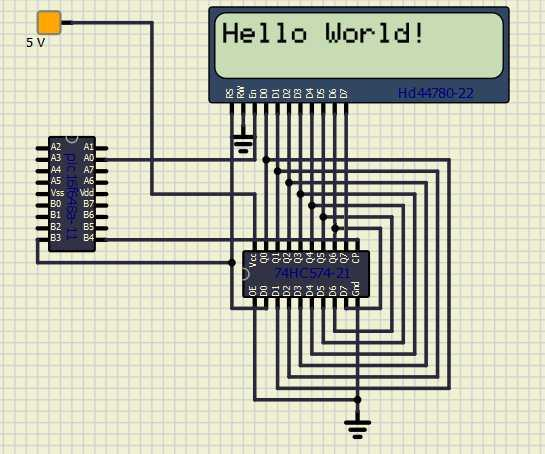
Relevant Constants:
Specific constants are used to control settings for the Liquid Crystal Display routines included with GCBASIC. To set these constants the main program should specific constants to support the connection mode using #define. When using 3-bit mode only three constants must be set.
| Constant Name | Controls | Default Value |
|---|---|---|
|
The I/O mode. |
|
|
The data pin used in 3-bit mode. |
Mandated |
|
The clock pin used in 3- bit mode. |
Mandated |
|
The enable pin used in 3- bit mode. |
Mandated |
Example:
#chip 16f628a, 4
#option explicit
;Setup LCD Parameters
#define LCD_IO 3
'Change ports as necessary
#define LCD_DB PORTb.3 ; databit
#define LCD_CB PORTb.4 ; clockbit
#define LCD_EB PORTa.0 ; enable bit
Dim BV as Byte
'Program Start
PRINT "GCBASIC"
Locate 1,0
PRINT "@2021"
Wait 4 s
DO Forever
CLS
WAIT 2 s
PRINT "Test LCDHex "
wait 3 s
CLS
wait 1 s
for bv = 0 to 16
locate 0,0
Print "DEC " : Print BV
locate 1,0
Print "HEX "
LCDHex BV
Locate 1, 8
LCDHEX BV, LeadingZeroActive
wait 500 ms
next
CLS
wait 1 s
Print "END TEST"
LOOP
See the separate sections of the Help file for the specifics of each Connection Mode.
For more help, see LCD_IO 0, LCD_IO 1, LCD_IO 2_74xx164, LCD_IO 2_74xx174, LCD_IO 4, LCD_IO 8, LCD_IO 10 or LCD_IO 12
LCD_IO 2_74xx174
LCD_IO 2_74xx174 has been deprecated as preferred method mode to connect an LCD display to a microcontroller via a shift register either a 74LS174 (or a 74LS164 with diode connected to pin 11). This method does not support backlight control and has no additional input/output pin.
See LCD_IO 2_74xx164 for the preferred method to connect an LCD display to a microcontroller via a shift register.
LCD_IO 4
Using connection mode 4:
To use connection mode 4 the R/W, RS, Enable control lines and the highest 4 data lines (DB4 through DB7) must be connected to the microcontroller.
Relevant Constants:
Specific constants are used to control settings for the Liquid Crystal Display routines included with GCBASIC. To set these constants the main program should specific constants to support the connection mode using #define. Constants required for connection mode 4.
Constants are required for 4-bit mode as follows.
| Constant Name | Controls | Default Value |
|---|---|---|
|
|
|
|
Must be 4 |
|
|
Specifies the output pin that is connected to Register Select on the LCD. |
Must be defined as |
|
Specifies the output pin that is connected to Read/Write on the LCD. The R/W pin can be disabled*. |
Must be defined as |
|
Specifies the output pin that is connected to Read/Write on the LCD. |
Must be defined as |
|
Output pin used to interface with bit 4 of the LCD data bus |
Must be defined as |
|
Output pin used to interface with bit 5 of the LCD data bus |
Must be defined as |
|
Output pin used to interface with bit 6 of the LCD data bus |
Must be defined as |
|
Output pin used to interface with bit 7 of the LCD data bus |
Must be defined as |
|
Specifies a delay between transmission of data nibbles to LCD or VFD. Usage must include number value and unit of time.
Only applicable when using LCD_IO 4 |
None. |
|
Specifies OCULAR OM1614 suppport. This changes the intialisation routine to a specific routine for the OCULAR devices. |
To specify explicit OCULAR_OM1614 support
The OCULAR devices requires LCD_RW |
The R/W pin can be disabled by setting the LCD_NO_RW constant. If this
is done, there is no need for the R/W to be connected to the chip, and
no need for the LCD_RW constant to be set. Ensure that the R/W line on
the LCD is connected to ground if not used.
For a code example download Four Wire LCD Example.
Also see for further code examples see Four Wire LCD Solutions.
See the separate sections of the Help file for the specifics of each Connection Mode.
For more help, see LCD_IO 0, LCD_IO 1, LCD_IO 2, LCD_IO 2_74xx164, LCD_IO 2_74xx174, LCD_IO 8, LCD_IO 10 or LCD_IO 12
LCD_IO 8
Using connection mode 8:
Using connection mode will require R/W, RS, Enable and all 8 data
lines.
The data lines must all be connected to the same I/O port, in sequential
order. For example, DB0 to PORTB.0, DB1 to PORTB.1 and so on, with DB7
going to PORTB.7.
Relevant Constants:
These constants are used to control settings for the Liquid Crystal
Display routines included with GCBASIC. To set them, place a line in the
main program file that uses #define to assign a value to the particular
constant.
Constants are required for 8-bit mode as follows.
| Constant Name | Controls | Default Value |
|---|---|---|
|
|
|
|
The I/O mode. Can be 2, 4 or 8. |
|
|
Specifies the output pin that is connected to Register Select on the LCD. |
Must be defined |
|
Specifies the output pin that is connected to Read/Write on the LCD. The R/W pin can be disabled*. |
Must be defined (unless R/W is disabled) |
|
Specifies the output pin that is connected to Read/Write on the LCD. |
Must be defined |
|
Output port used to interface with LCD data bus |
Must be defined |
|
Drives the port with |
Optional |
The R/W pin can be disabled by setting the LCD_NO_RW constant. If this
is done, there is no need for the R/W to be connected to the chip, and
no need for the LCD_RW constant to be set. Ensure that the R/W line on
the LCD is connected to ground if not used.
For a code example download Eight Wire LCD example.
For code examples see Eight Wire Examples.
See the separate sections of the Help file for the specifics of each Connection Mode.
For more help, see LCD_IO 0, LCD_IO 1, LCD_IO 2, LCD_IO 2_74xx164, LCD_IO 2_74xx174, LCD_IO 4, LCD_IO 10 or LCD_IO 12
LCD_IO 10
LCD_IO 10 provides support for character LCD modules that use an I2C/TWI interface based on the PCF8574 or PCF8574A I/O expander. These I/O expanders are commonly found on low‑cost LCD “I2C backpacks” sold under many brand names (YwRobot, Sainsmart, Joy-It, generic blue/black I2C adapters, etc.).
The PCF8574 device converts an I2C bus signal into 8 digital output lines, which are then wired to the LCD’s RS, EN, D4–D7, and backlight control pins.
LCD_IO 10 implements the correct signalling for this type of I/O expander.
Use LCD_IO 10 whenever your LCD module uses a PCF8574‑based I2C
adapter, regardless of brand or PCB layout. You can configure the specific LCD port layout, if required.
To use mode 10:
-
Configure your I2C/TWI pins normally in your GCBASIC program.
-
Define the LCD type by using
LCD_IO 10 -
Set the I2C address of the PCF8574 adapter, if required. Typical PCF8574 I2C addresses range from 0x40 to 0x4E, depending on the A0–A2 jumper settings on the adapter board.
-
Optionally set LCD speed and backlight behaviour.
-
Optionally set the LCD port layout.
Relevant Constants
These constants configure the Liquid Crystal Display routines in
GCBASIC. Add them to your main program using #define.
| Constant Name | Controls | Value |
|---|---|---|
|
Selects the I/O mode. Must be 10 for PCF8574 I2C LCDs. |
|
Constant Name |
Controls |
Default |
I2C_LCD_E |
LCD Enable - Expander Port Bit |
|
I2C_LCD_RW |
LCD RW - Expander Port Bit |
|
I2C_LCD_RS |
LCD RS - Expander Port Bit |
|
I2C_LCD_BL |
LCD Back Light - Expander Port Bit |
|
I2C_LCD_D4 |
LCD Data Bit4 - Expander Port Bit |
|
I2C_LCD_D5 |
LCD Data Bit5 - Expander Port Bit |
|
I2C_LCD_D6 |
LCD Data Bit6 - Expander Port Bit |
|
I2C_LCD_D7 |
LCD Data Bit7 - Expander Port Bit |
|
|
PCF8574 I2C address (A0–A2 = 111) |
|
|
PCF8574 I2C address (A0–A2 = 110) |
|
|
PCF8574 I2C address (A0–A2 = 101) |
|
|
PCF8574 I2C address (A0–A2 = 100) |
|
|
PCF8574 I2C address (A0–A2 = 011) |
|
|
PCF8574 I2C address (A0–A2 = 010) |
|
|
PCF8574 I2C address (A0–A2 = 001) |
|
|
PCF8574 I2C address (A0–A2 = 000) |
|
Example Usage
This example demonstrates using two PCF8574‑based I2C LCDs on the same I2C bus. Up to eight LCDs may be connected simultaneously, each with a unique PCF8574 address (0x40–0x4E).
Set up I2C-LCD
#DEFINE LCD_IO 10
/* LCD_IO 10 is for PCF8574-based I2C LCD adapters.
Examples include YwRobot LCD1602 IIC V1, Sainsmart LCD_PIC,
and most generic blue/black I2C LCD backpacks.
LCD_IO 12 is used for adapters based on the Ywmjkdz layout
with the potentiometer bent over the IC.
*/
#DEFINE LCD_I2C_ADDRESS_1 0x4E ' First LCD at address 0x4E
PRINT "Hello World"
This example demonstrates using two PCF8574‑based I2C LCDs on the same I2C bus. Up to eight LCDs may be connected simultaneously, each with a unique PCF8574 address (0x40–0x4E).
Set up I2C-LCD
#DEFINE LCD_IO 10
/* LCD_IO 10 is for PCF8574-based I2C LCD adapters.
Examples include YwRobot LCD1602 IIC V1, Sainsmart LCD_PIC,
and most generic blue/black I2C LCD backpacks.
LCD_IO 12 is used for adapters based on the Ywmjkdz layout
with the potentiometer bent over the IC.
*/
#DEFINE LCD_I2C_ADDRESS_1 0x4E ' First LCD at address 0x4E
#DEFINE LCD_I2C_ADDRESS_6 0x44 ' Second LCD at address 0x44
' Switch between LCDs:
LCD_I2C_ADDRESS_Current = LCD_I2C_ADDRESS_6 ' Activate second LCD
PRINT "Hello World"
LCD_I2C_ADDRESS_Current = LCD_I2C_ADDRESS_1 ' Activate first LCD
PRINT "Hello World"
See other sections of the Help file for details on alternative connection modes.
For more help, see LCD_IO 0, LCD_IO 1, LCD_IO 2, LCD_IO 2_74xx164, LCD_IO 2_74xx174, LCD_IO 4, LCD_IO 8, LCD_IO 12
LCD_IO 10 Port Configuration
LCD_IO 10 provides support for character LCD modules that use an I2C/TWI interface based on the PCF8574 or PCF8574A I/O expander. These expanders are commonly found on low‑cost LCD “I2C backpacks” sold under many brand names (YwRobot, Sainsmart, Joy‑It, generic blue/black adapters, and others).
Using mode 10
When using LCD_IO 10, the target PCF8574 or PCF8574A I/O expander port is configured by default as shown in the table below. Each bit of the byte variable i2c_lcd_byte is mapped to the appropriate LCD control or data line.
| Constant Name | Controls | Default |
|---|---|---|
I2C_LCD_E |
LCD Enable – Expander Port Bit |
|
I2C_LCD_RW |
LCD RW – Expander Port Bit |
|
I2C_LCD_RS |
LCD RS – Expander Port Bit |
|
I2C_LCD_BL |
LCD Backlight – Expander Port Bit |
|
I2C_LCD_D4 |
LCD Data Bit 4 – Expander Port Bit |
|
I2C_LCD_D5 |
LCD Data Bit 5 – Expander Port Bit |
|
I2C_LCD_D6 |
LCD Data Bit 6 – Expander Port Bit |
|
I2C_LCD_D7 |
LCD Data Bit 7 – Expander Port Bit |
|
If your I2C LCD adapter or PCB uses a different wiring arrangement, you can override the default configuration to match your hardware.
These overrides should be placed in your main program.
To apply an alternative configuration, define the following eight constants. Doing so replaces the default mappings shown in the table above.
#DEFINE I2C_LCD_E I2C_LCD_BYTE.1
#DEFINE I2C_LCD_RW I2C_LCD_BYTE.2
#DEFINE I2C_LCD_RS I2C_LCD_BYTE.0
#DEFINE I2C_LCD_BL I2C_LCD_BYTE.3
#DEFINE I2C_LCD_D4 I2C_LCD_BYTE.7
#DEFINE I2C_LCD_D5 I2C_LCD_BYTE.6
#DEFINE I2C_LCD_D6 I2C_LCD_BYTE.5
#DEFINE I2C_LCD_D7 I2C_LCD_BYTE.4LCD_IO 12
Using connection mode 12:
The LCD is controlled via I2C. A type 12 is the Ywmjkdz I2C adapter with potentiometer variable resistor) bent over top of chip. To use mode 12 you must define the I2C ports as normal in your GCB code. Then, define the LCD type, set the I2C_address of the LCD adapter and the LCD speed, if required.
Relevant Constants:
These constants are used to control settings for the Liquid Crystal
Display routines included with GCBASIC. To set them, place a line in the
main program file that uses #define to assign a value to the particular
constant.
When using 2-bit mode only three constants must be set - all others can be ignored.
| Constant Name | Controls | Value |
|---|---|---|
|
I/O mode |
|
|
Address of I2C adapter |
Default |
|
Address of I2C adapter |
Not set |
|
Address of I2C adapter |
Not set |
|
Address of I2C adapter |
Not set |
To set the correct address see the picture below:

For code examples see I2C LCD Solutions.
See the separate sections of the Help file for the specifics of each Connection Mode.
For more help, see LCD_IO 0, LCD_IO 1, LCD_IO 2 LCD_IO 2_74xx164, LCD_IO 2_74xx174, LCD_IO 4, LCD_IO 8, LCD_IO 10
LCD_IO 12 Port Configuration
Using mode 12:
When using I2C LCD mode 12 the target I2C device address is setup as
shown below. Each bit of the the variable i2c_lcd_byte is defined to
address the correct LCD display port.
i2c_lcd_e = i2c_lcd_byte.4
i2c_lcd_rw = i2c_lcd_byte.5
i2c_lcd_rs = i2c_lcd_byte.6
i2c_lcd_bl = i2c_lcd_byte.7
i2c_lcd_d4 = i2c_lcd_byte.0
i2c_lcd_d5 = i2c_lcd_byte.1
i2c_lcd_d6 = i2c_lcd_byte.2
i2c_lcd_d7 = i2c_lcd_byte.3
If you have an I2C LCD display adapter with a different set of connection of the adapter then change this configuration to suit the specific of the adapter as follows. This should be done in the your main program code.
#define i2c_lcd_e i2c_lcd_byte.4
#define i2c_lcd_rw i2c_lcd_byte.5
#define i2c_lcd_rs i2c_lcd_byte.6
#define i2c_lcd_bl i2c_lcd_byte.7
#define i2c_lcd_d4 i2c_lcd_byte.3
#define i2c_lcd_d5 i2c_lcd_byte.2
#define i2c_lcd_d6 i2c_lcd_byte.1
#define i2c_lcd_d7 i2c_lcd_byte.0
LCD_IO 14
Using connection mode 14:
Using this LCD IO methof the LCD is controlled via an SPI expander.
To use mode 14 you must define the SPI ports as normal in your GCB code. Then, define the LCD type, set the SPI address of the SPI expander, and, the LCD speed, if required.
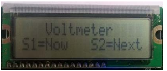
Relevant Constants:
These constants are used to control settings for the LCD routines included with GCBASIC. To set them, place a line in the main program file that uses #define to assign a value to the particular constant.
When using this mode only three constants are mandated - all others can be ignored.
| Constant Name | Controls | Value |
|---|---|---|
|
I/O mode |
|
|
Microcontroller SPI data out port |
Required |
|
Microcontroller SPI clock out port |
Required |
|
Microcontroller SPI chip select port |
Required |
Connectivity
The connectivity is shown below. The microcontroller connections are as shown below. This is an example using the Microchip Explorer 8 board.
RC3 > Expander SPI SCK ( clock)
RC5 > Expander SPI SI (slave in)
RA2 > Expander SPI CS ( chip select) - could be set to 0v0
RB5 > Expander Reset ( optional)
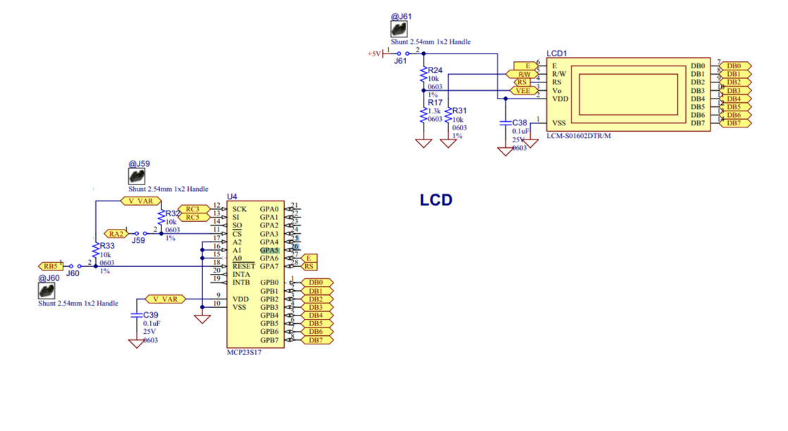
Optional configuration
There are some options you can tweak. See the example setup below. You can play with the use of hardware or software SPI, SPI frequency ( HWSPIMODE MASTERFAST). LED speed, the connectivity between the expander and the LCD and otheroptions.
//Constants - LCD connectivity type; controls whether to use HW SPI; The inter character delay
#define LCD_IO 14
#define LCD_HARDWARESPI
#define LCD_SPEED FAST
#define HWSPIMODE MASTERFAST
//These are the phyiscal connections from the expander to the LCD. These are automatically set in the library and are shown here purely for clarity.
#define LCD_SPI_EXPD_ADDRESS 0x40 // address of the expander
#define LCD_SPI_EXPANDER_E_ADDRESS 0x40 // GPA6 on the expander
#define LCD_SPI_EXPANDER_RS_ADDRESS 0x80 // GPA7 on the expander
//Pin mappings for LCD IO SPI Expander
#define LCD_SPI_DO portc.5 // constant is mandated
#define LCD_SPI_SCK portc.3 // constant is mandated
#define LCD_SPI_CS porta.2 // constant is required.
// Optional(s) reset Port.Pin connection to expander, select one.
// #define LCD_SPI_RESET_IN portb.5
#define LCD_SPI_RESET_OUT portb.5
For code examples see LCD Solutions.
See the separate sections of the Help file for the specifics of each Connection Mode.
For more help, see LCD_IO 0, LCD_IO 1, LCD_IO 2 LCD_IO 2_74xx164, LCD_IO 2_74xx174, LCD_IO 4, LCD_IO 8, LCD_IO 10, LCD_IO 12
LCD_IO 14 Port Configuration
Using mode 14:
When using LCD mode 14 this is an example program to show a working solution,
#chip 18F67K40, 8
#option explicit
'PPS Tool version: 0.0.6.3
// Generated for 18f67k40
#startup InitPPS, 85
#define PPSToolPart 18f67k40
Sub InitPPS
#ifdef LCD_HARDWARESPI
SSP1CLKPPS = 0x13; //RC3->MSSP1:SCK1;
RC3PPS = 0x19; //RC3->MSSP1:SCK1;
RC5PPS = 0x1A; //RC5->MSSP1:SDO1;
SSP1DATPPS = 0x14; //RC4->MSSP1:SDI1;
#endif
End Sub
//Constants - LCD connectivity type
#define LCD_IO 14
//Comment out to use software SPI
#define LCD_HARDWARESPI
#define LCD_SPEED FAST
//Optional. Can also select MASTERSLOW or MASTER. The compiler will set automatically.
#define HWSPIMODE MASTERFAST
//These are phyiscal connections from the expander to the LCD. These are automatically set in the library and are shown here purely for clarity.
#define LCD_SPI_EXPD_ADDRESS 0x40
#define LCD_SPI_EXPANDER_E_ADDRESS 0x40 // GPA6 on the expander
#define LCD_SPI_EXPANDER_RS_ADDRESS 0x80 // GPA7 on the expander
//Mandated Pin mappings for LCD IO SPI Expander
#define LCD_SPI_DO portc.5
#define LCD_SPI_SCK portc.3
#define LCD_SPI_CS porta.2
// Optional(s) reset Port.Pin connection to expander, select one.
// #define LCD_SPI_RESET_IN portb.5
#define LCD_SPI_RESET_OUT portb.5
; ----- Main body of program commences here.
ClS
Print "Hello World"
LCD_IO 16
Using connection mode 16:
Using this LCD IO methof the LCD is controlled via the Microchip PIC16LF72 SPI expander.
To use mode 16 you must define the SPI ports as shown below.
Relevant Constants:
These constants are used to control settings for the LCD routines included with GCBASIC. To set them, place a line in the main program file that uses #define to assign a value to the particular constant.
When using this mode only three constants are mandated - all others can be ignored.
| Constant Name | Controls | Value |
|---|---|---|
|
I/O mode |
|
|
Microcontroller SPI data out port |
Required |
|
Microcontroller SPI clock out port |
Required |
Connectivity
The connectivity is shown below. The microcontroller connections are as shown below. This is an example using the Microchip PICDEM 4 2003 board.
//Constants - LCD connectivity type;
#DEFINE LCD_IO 16
//PIN MAPPINGS FOR PIC16LF72 LCD IO SPI EXPANDER
// CONSTANT IS MANDATED - DATA LINE
#DEFINE LCD_SPI_DO PORTB.2
// CONSTANT IS MANDATED - CLOCK LINE
#DEFINE LCD_SPI_SCK PORTB.5
//! Main program
Print "GCBASIC Rocks"
End
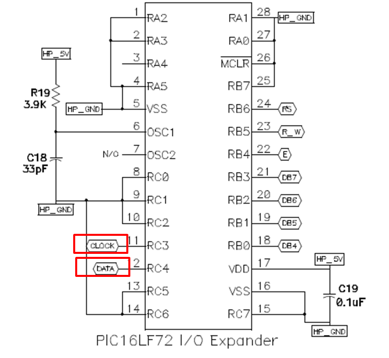
For code examples see LCD Solutions.
See the separate sections of the Help file for the specifics of each Connection Mode.
For more help, see LCD_IO 0, LCD_IO 1, LCD_IO 2 LCD_IO 2_74xx164, LCD_IO 2_74xx174, LCD_IO 4, LCD_IO 8, LCD_IO 10, LCD_IO 12
LCD_IO 107
Using connection mode 107:
The LCD is controlled via the serial port. A type 107 is a K107 serial adapter. To use mode 107 you must define the serial port as normal in your GCB code. Then, serial speed to match the K107 adapter.
Relevant Constants:
These constants are used to control settings for the Liquid Crystal
Display routines included with GCBASIC. To set them, place a line in the
main program file that uses #define to assign a value to the particular
constant.
When using 107 mode only one constants must be set - all others can be ignored.
| Constant Name | Controls | Value |
|---|---|---|
|
I/O mode |
|
Example Code:
#chip 16f18313
#option Explicit
'Generated by PIC PPS Tool for GCBASIC
'Generated for 16f18313
'
#startup InitPPS, 85
#define PPSToolPart 16f18313
Sub InitPPS
'Module: EUSART
RA5PPS = 0x0014 'TX > RA5
End Sub
'Template comment at the end of the config file
'USART settings for USART1
#define USART_BAUD_RATE 115200
#define USART_TX_BLOCKING
#define USART_DELAY OFF
#define LCD_IO 107 'K107
do Forever
CLS
Print "GCBASIC 2021"
Locate 1, 0
Print "Reading ADC ANA0"
Locate 3, 0
Print "Scaled = "
Print Scale( ReadAD( ANA0 ), 0, 236, 0, 100 )
wait 100 ms
loop
See the separate sections of the Help file for the specifics of each Connection Mode.
For more help, see LCD_IO 0, LCD_IO 1, LCD_IO 2 LCD_IO 2_74xx164, LCD_IO 2_74xx174, LCD_IO 4, LCD_IO 8, LCD_IO 10
LCD_VARIANT
Using LCD_VARIANT:
Some LCDs are non-standard.
The non-standard LCDs may have a different memory architecture where the memory is non-consective or different delay timing is required for the LCD IC.
Use LCD_VARIANT to change the operating behaviour of GCBASIC with respect to LCD operations.
If a LCD_VARIANT adaption has been created in the library then the non-standard LCD can be supported.
#DEFINE LCD_VARIANT 1601a
Use #define LCD_VARIANT 1601a to use this sub variant. Requires a LCD_IO then this sub type modifier.
This variant has a non consective memory as shown in the diagram below.
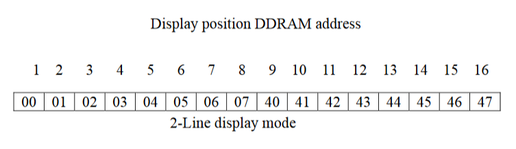
Example:
This example shows how to use the LCD_VARIANT constant. This example shows the use of software I2C - any LCD mode can be used not just software I2C.
#chip tiny84,1
'Set up LCD
#define LCD_IO 10
#define LCD_VARIANT 1601a
#define LCD_WIDTH 16
'You may need to use SLOW or MEDIUM if your LCD is a slower device.
#define LCD_SPEED FAST
' ----- Define Hardware settings
' Define I2C settings - CHANGE PORTS FOR YOUR NEEDS
#define LCD_I2C_Address 0x0E
#define I2C_MODE Master
#define I2C_DATA PORTA.4
#define I2C_CLOCK PORTA.5
#define I2C_DISABLE_INTERRUPTS ON
'You may need to invert these states. Dependent of LCD I2C adapter.
#define LCD_Backlight_On_State 1
#define LCD_Backlight_Off_State 0
; ----- Main body of program commences here.
Locate 0,0
PRINT "GCBASIC"
Do
Loop
For code examples see I2C Variants LCD Solutions.
See the separate sections of the Help file for the specifics of each Connection Mode.
For more help, see LCD_IO 0, LCD_IO 1, LCD_IO 2 LCD_IO 2_74xx164, LCD_IO 2_74xx174, LCD_IO 4, LCD_IO 8, LCD_IO 10
LCD_SPEED
Using LCD_SPEED:
The communication performance of a LCD display can be controlled via a #DEFINE.
This method allows the timing to be optimised.
Example
#DEFINE LCD_SPEED FAST
| Define | Required Connections |
|---|---|
|
Options are: |
If LCD_SPEED is not defined, the speed defaults to SLOW
To change the performance (communications speed) of the LCD use #DEFINE LCD_SPEED. This method allows the timing to be optimised.
Example
#DEFINE LCD_SPEED FAST
If LCD_SPEED is not defined, the speed defaults to SLOW
Speed Parameter OPTIMAL
WHEN LCD_NO_RW is not defined, OPTIMAL disables fixed delays and allows the LCD operate as fast as it can.
In this mode, The the busy flag is polled before each byte is sent to the HD44780 controller. This not only optimizes speed, but also assures that data is not sent to the diplay controler until it is ready to receive the data.
With most displays this equates to a speed of about 30,000 characters per second. For comparision about 10 times faster than I2C using a PC8574 Expander (See LCD_IO 10 or See LCD_IO 112)
OPTIMAL is only supported in LCD_IO 4,8 and only when LCD_NO_RW is not defined (RW Mode)
When #DEFINE LCD_NO_RW is defined, reading data from the HD44780 is not possible since this disables Read Mode on the controller. In this case busy flag checking is not available and the GET subroutine is not avaiable.
In order to enable busy flag checking, and, therefore to use the GET command the following criteria must be true.
-
LCD I/O Mode must be either 4-wire or 8-wire
-
#DEFINE LCD_NO_RWis not defined -
An I\O pin is connected between the microcontroller and the RW connection on the LCD Display
-
'DEFINE LCD_RW port.pinis defined in the GCBASIC source code
Example:
#DEFINE LCD_IO 4 #DEFINE LCD_SPEED OPTIMAL #DEFINE LCD_WIDTH 20 ;specified lcd width for clarity only. 20 is the default width #DEFINE LCD_DB7 PORTB.5 #DEFINE LCD_DB6 PORTB.4 #DEFINE LCD_DB7 PORTB.3 #DEFINE LCD_DB6 PORTB.2 #DEFINE LCD_RW PORTA.3 'Must be defined for RW Mode #DEFINE LCD_RS PORTA.2 #DEFINE LCD_ENABLE PORTA.1
LCD_WIDTH
Using LCD_WIDTH:
This constant changes the width characteristics of a LCD display. The standard width is assumed to be 20 characters.
This constant allows the width to be optimised for specific LCD chipsets.
Example
#DEFINE LCD_WIDTH 16
| Define | Required Connections |
|---|---|
|
Default is 20 |
If LCD_WIDTH is not defined, the WIDTH defaults to 20
CLS
Syntax:
CLS
Command Availability:
Available on all microcontrollers.
Explanation:
The CLS command clears the contents of the LCD, and returns the cursor
to the top left corner of the screen
Example :
'A Flashing text "Hello World" program for GCBASIC
'General hardware configuration
#chip 16F877A, 20
'LCD connection settings
#define LCD_IO 8
#define LCD_DATA_PORT PORTC
#define LCD_RS PORTD.0
#define LCD_RW PORTD.1
#define LCD_Enable PORTD.2
#define LCD_WIDTH 20 ;specified lcd width for clarity only. 20 is the default width
'Main routine
Do
Print "Hello World"
Wait 1 sec
CLS
Wait 1 sec
Loop
For more help, see LCD Overview
Supported in <LCD.H>
Get
Syntax:
var = Get(Line, Column)
Command Availability:
Available on all microcontrollers with the LCD R/W line (pin 5) connected and if the following constant definition is used;
#define LCD_RW. Only available when the LCD is connected using the 4 or 8 bit mode and when the constant definition
#define LCD_NO_RW is NOT used.
Explanation:
The Get function reads the ASCII character code at a given location on
the LCD.
For more help, see Put, LCD Overview
Supported in <LCD.H>
LCDBacklight
Syntax:
LCDBacklight ( On | Off )
Command Availability:
Available on all microcontrollers
Explanation:
Sets the LCD backlight on or off
Do not connect the LCD backlight directly to the microcontroller! Always refer to the datasheet for the correct method to drive the LCD backlight.
For 0, 4, 8, 404 LCD types you must define the controlling port.pin for the LCD backlight.
'this port.pin is connected to the LCD backlight via a suitable circuit
#define LCD_Backlight porta.4
...
...
...
...
LCDBacklight ( On )
.... more user code...
LCDBacklight ( Off )
Inverting the State of the LCD
You may need to invert the state of the LCD backlight control port. This can be achieved by setting the following constants.
'Invert the LCD Backlight States to suit the circuit board
#define LCD_Backlight_On_State 0 'the default constant value is 1
#define LCD_Backlight_Off_State 1 'the default constant value is 0
The diagram below shows a method to connect the LCD backlight to a microcontroller.
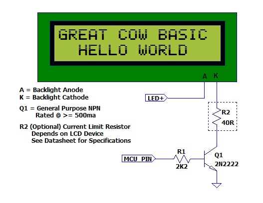 The diagram above was provided by William Roth, January 2015.
Supported in <LCD.H>
LCDCreateChar
Syntax:
LCDCreateChar char, chardata()
Command Availability:
Available on all microcontrollers.
Explanation:
The LCDCreateChar command is used to send a custom character to the LCD.
Each character on the LCD is made up from an 8 row by 5 column (5x8) matrix of pixels. The data to be sent to the LCD is composed of an 8 element array, where each element corresponds to a row. Inside each element, the 5 lowest bits make up the data for the corresponding row. When a bit is set a dot will be drawn at the matching location; when it is cleared, no dot will appear.
An array of more than 8 elements may be used, but only the first 8 will be read.
char is the ASCII value of the character to create. ASCII codes 0
through 7 are usually used to store custom characters.
chardata() is an array containing the data for the character.
Example:
'This program draws a smiling face character
'General hardware configuration
#chip 16F877A, 20
'LCD connection settings
#define LCD_IO 8
#define LCD_WIDTH 20 ;specified lcd width for clarity only. 20 is the default width
#define LCD_DATA_PORT PORTC
#define LCD_RS PORTD.0
#define LCD_RW PORTD.1
#define LCD_Enable PORTD.2
'Create an array to store the character until it is copied
Dim CharArray(8)
'Set the array to hold the character
'Binary has been used to improve the readability of the code, but is not essential
CharArray(1) = b'00011011'
CharArray(2) = b'00011011'
CharArray(3) = b'00000000'
CharArray(4) = b'00000100'
CharArray(5) = b'00000000'
CharArray(6) = b'00010001'
CharArray(7) = b'00010001'
CharArray(8) = b'00001110'
'Copy the character from the array to the LCD
LCDCreateChar 0, CharArray()
'Draw the custom character
LCDWriteChar 0
For more help, see LCDWriteChar, LCD Overview
Supported in <LCD.H>
LCDCreateGraph
Syntax:
LCDCreateGraph value
Command Availability:
Available on all microcontrollers.
Explanation:
The LCDCreateGraph command will create a graph like character which can then be displayed on the LCD
Example :
;Chip Settings
#chip 16F88,8
;Defines (Constants)
#define LCD_IO 4
#define LCD_WIDTH 20 ;specified lcd width for clarity only. 20 is the default width
#define LCD_RS PORTA.6
#define LCD_NO_RW
#define LCD_Enable PORTA.7
#define LCD_DB4 PORTB.4
#define LCD_DB5 PORTB.5
#define LCD_DB6 PORTB.6
#define LCD_DB7 PORTB.7
Locate 0,0
Print "Reset"
wait 1 s
cls
Graph_Tests:
cls
'Draw the custom character - fill the LCD
repeat 64
LCDWriteChar 0
end Repeat
' Update the characters at high speed without re-printing on LCD
for graphvalue = 0 to 8
LCDCreateGraph ( 0 , graphvalue )
wait 100 ms
next
Supported in <LCD.H>
LCDCmd
Syntax:
LCDCMD value
Command Availability:
Available on all microcontrollers.
Explanation:
This command set LCD specific instructions to the LCD display. As shown in the table below.
| INSTRUCTION | Decimal | Hexadecimal |
|---|---|---|
Scroll display one character right (all lines) |
28 |
1E |
Scroll display one character left (all lines) |
24 |
18 |
Home (move cursor to top/left character position) |
2 |
2 |
Move cursor one character left |
16 |
10 |
Move cursor one character right |
20 |
14 |
Turn on visible underline cursor |
14 |
0E |
Turn on visible blinking-block cursor |
15 |
0F |
Make cursor invisible |
12 |
0C |
Blank the display (without clearing) |
8 |
08 |
Restore the display (with cursor hidden) |
12 |
0C |
Clear Screen |
1 |
01 |
Set cursor position (DDRAM address) |
128 + addr |
80+ addr |
Set pointer in character-generator RAM (CG RAM address) |
64 + addr |
40+ addr |
Example 1:
;Chip Settings
#chip 16F88,8
;Defines (Constants)
#define LCD_IO 4
#define LCD_WIDTH 20 ;specified lcd width for clarity only. 20 is the default width
#define LCD_RS PORTA.6
#define LCD_NO_RW
#define LCD_Enable PORTA.7
#define LCD_DB4 PORTB.4
#define LCD_DB5 PORTB.5
#define LCD_DB6 PORTB.6
#define LCD_DB7 PORTB.7
Locate 0,0
Print "Reset"
wait 1 s
cls
LCD_Command_Tests:
locate 0,8
print "123456"
'Scroll display one character right (all lines) 28
'
lcdcmd 28
wait 1 s
lcdcmd 28
wait 1 s
lcdcmd 28
wait 1 s
lcdcmd 28
wait 1 s
'Scroll display one character left (all lines) 24
'
lcdcmd 24
wait 1 s
lcdcmd 24
wait 1 s
lcdcmd 24
wait 1 s
lcdcmd 24
wait 1 s
'Home (move cursor to top/left character position) 2
'
lcdcursor flash
lcdcmd 2
wait 1 s
'Move cursor one character left 16
'
lcdcursor flash
locate 0,8
lcdcmd 16
wait 1 s
lcdcmd 16
wait 1 s
lcdcmd 16
wait 1 s
lcdcmd 16
wait 1 s
'Move cursor one character right 20
'
lcdcmd 20
wait 1 s
lcdcmd 20
wait 1 s
lcdcmd 20
wait 1 s
lcdcmd 20
wait 1 s
Example 2:
#chip 16F877A,20
#option Explicit
'Use LCD in 4 pin mode and define LCD pins
#define LCD_IO 4
#define LCD_WIDTH 20 ;specified lcd width for clarity only. 20 is the default width
#define LCD_RW PORTE.1
#define LCD_RS PORTE.0
#define LCD_Enable PORTE.2
#define LCD_DB4 PORTD.4
#define LCD_DB5 PORTD.5
#define LCD_DB6 PORTD.6
#define LCD_DB7 PORTD.7
;Here are various LCD commands which can be used.
;These are the LCD commands for the HD44780 controller
#define clrHome = 1 ;clear the display, home the cursor
#define home = 2 ;home the cursor only
#define RtoL = 4 ;print characters right to left
#define insR = 5 ;insert characters to right
#define LtoR = 6 ;print characters left to right
#define insL = 7 ;insert characters to left
#define lcdOff = 8 ;LCD screen off
#define lcdOn = 12 ;LCD screen on, no cursor
#define curOff = 12 ;an alias for the above
#define block = 13 ;LCD screen on, block cursor
#define under = 14 ;LCD screen on, underline cursor
#define undblk = 15 ;LCD screen on, blinking and underline cursor
#define CLeft = 16 ;cursor left
#define CRight = 20 ;cursor right
#define panR = 24 ;pan viewing window right
#define panL = 28 ;pan viewing window left
#define bus4 = 32 ;4-bit data bus mode
#define bus8 = 48 ;8-bit data bus mode
#define mode1 = 32 ;one-line mode (alias)
#define mode2 = 40 ;two-line mode
#define line1 = 128 ;go to start of line 1
#define line2 = 192 ;go to start of line 2
;----- Variables
dim char, msn, lsn, index, ii as byte
;----- Main Program
LoadEeprom ;load the EEprom with strings
do forever
printMsg(0) ;print first message
wait 3 S ;pause 3 seconds
printMsg(2) ;print next message
wait 3 S ;pause 3 seconds
repeat 5 ;blink it five times
LCDCmd(lcdOff) ;display off
wait 500 mS ;pause
LCDCmd(lcdOn) ;display on
wait 500 mS ;pause
end repeat
wait 1 S ;pause before next demo
;demonstrate panning
printMsg(4) ;print next message
wait 3 S ;pause 3 seconds
repeat 16
LCDCmd(panL) ;pan left a step at a time
wait 300 mS ;slow down to avoid blur
end repeat
repeat 16
LCDCmd(panR) ;then pan right
wait 300 mS
end repeat
wait 1 S ;pause before next demo
;demonstrate moving the cursor
printMsg(6) ;print next message
wait 3 S ;pause 3 seconds
LCDHome
LCDCmd(under) ;choose underline cursor
for ii = 0 to 15 ;move cursor across first line
LCDCmd(line1+ii)
wait 200 mS
next i
for ii = 0 to 15 ;move cursor across second line
LCDCmd(line2+ii)
wait 200 mS
next i
for ii = 15 to 0 step -1 ;move cursor back over second line
LCDCmd(line2+ii)
wait 200 mS
next i
for ii = 15 to 0 step -1 ;move cursor back over first line
LCDCmd(line1+ii)
wait 200 mS
next i
wait 3 S
;demonstrate blinking block cursor
printMsg(8) ;print next message
LCDHome ;home the cursor
LCDCmd(block) ;choose blinking block cursor
wait 4 S ;pause 4 seconds
LCDCmd(mode1) ;change to one long line mode
LCDHome ;home the cursor again
LCDCmd(curOff) ;and disable it
;demonstrate scrolling a lengthy one-line marquee
for ii = 0xd0 to 0xff ;print next message - the remaining EEPROM
EPread ii, char ;fetch directly from eeprom
print chr(char)
next i
wait 1 S
LCDHome ;home cursor once more
repeat 141 ;scroll message twice
LCDCmd(panR)
wait 250 mS
end repeat
wait 2 S
LCDCmd(mode2) ;change back to two line mode
CLS ;clear the screen
;demonstrate all of the characters
printMsg(11) ;print next message
for ii = 33 to 127 ;print first batch of ASCII characters
LCDCmd(line1+12) ;overwrite each character displayed
print chr(ii) ;this is the ASCII code
wait 500 mS
next i
for ii = 161 to 255 ;print next batch of ASCII characters
LCDCmd(line1+12)
print chr(ii)
wait 500 mS
next i
;say good-bye
LCDCmd(line2)
printMsg(11) ;print next message
LCDHome ;home the cursor
loop
end
;----- Print a message to the LCD
;The parameter 'row' points to the start of the string.
sub printMsg(in row as byte, in Optional StringLength As Byte = 15)
Locate 0, 0 ;get set for first line
for ii = 0 to StringLength
index = row*16+ii
EPread index, char ;fetch next character and
print chr(char) ;transmit to the LCD
next
Locate 1,0 ;get set for second line
for ii = 0 to StringLength
index = (row+1)*16+ii
EPread index, char ;fetch next character and
print chr(char) ;transmit to the LCD
next
end sub
sub loadEeprom
' Strings for EEPROM, Strings should be limited to 16 characters for the first 13 sstrings, then a long string to fill eeprom
WriteEeprom "First we'll show"
WriteEeprom "this message. "
WriteEeprom "Then we'll blink"
WriteEeprom "five times. "
WriteEeprom "Now lets pan "
WriteEeprom "left and right. "
WriteEeprom "Watch the line "
WriteEeprom "cursor move. "
WriteEeprom "A block cursor "
WriteEeprom "is available. "
WriteEeprom "Characters: "
WriteEeprom "Bye! "
WriteEeprom "in one line mode"
WriteEeprom "Next well scroll this long message as a marquee"
end sub
; Write to the device eeprom
sub WriteEeprom ( in Estring() )
Dim eeLocation as Byte 'if the EEPROM size was larger than 256 bytes then this would need to be a WORD
for eeLocation = 1 to len ( Estring )
HSersend Estring( eeLocation )
epwrite eeLocation, Estring( eeLocation )
next
end sub
Supported in <LCD.H>
LCDCursor
Syntax:
LCDCursor value
Command Availability:
Available on all microcontrollers.
Explanation:
The LCDCursor command will accept the following parameters:
LCDON, LCDOFF, CURSORON, CURSOROFF, FLASHON, FLASHOFF
FLASH, and ON/OFF have been retained for backward compatibility with
older releases of GCB.
LCDON will turn on (restore) the LCD display.
LCDOFF will turn off (hide) the LCD display.
CURSORON will turn on the cursor.
CURSOROFF will turn off the cursor.
FLASHON will flash the cursor.
FLASHOFF will stop flashing the cursor.
Example : #config osc = intrc
#chip 16f877a, 8
;Defines (Constants)
#define LCD_IO 4
#define LCD_WIDTH 20 ;specified lcd width for clarity only. 20 is the default width
#define LCD_RS PORTA.6
#define LCD_NO_RW
#define LCD_Enable PORTA.7
#define LCD_DB4 PORTB.4
#define LCD_DB5 PORTB.5
#define LCD_DB6 PORTB.6
#define LCD_DB7 PORTB.7
Start:
CLS
WAIT 3 s
PRINT "START DEMO"
locate 1,0
PRINT "DISPLAY ON"
wait 3 s
CLS
Locate 0,0
Print "Cursor ON"
Locate 1,0
LCDcursor CursorOn
wait 3 S
CLS
LCDcursor CursorOFF
locate 0,0
Print "Cursor OFF"
wait 3 s
CLS
Locate 0,0
Print "FLASH ON"
Locate 1,0
LCDcursor FLASHON
wait 3 s
CLS
locate 0,0
Print "FLASH OFF"
LCDCURSOR FLASHOFF
wait 3 sec
Locate 0,0
Print "CURSOR&FLASH ON" 'Both are on at the same time
locate 1,0
LCDCURSOR CURSORON
LCDCURSOR FLASHON
Wait 3 sec
Locate 0,0
Print "CURSOR FLASH OFF"
locate 1,0
LCDCURSOR CursorOFF
LCDCURSOR FLASHOFF
Wait 3 sec
CLS
Locate 0,4
PRINT "Flashing"
Locate 1,4
Print "Display"
wait 500 ms
repeat 5
LCDCURSOR LCDOFF
wait 500 ms
LCDCURSOR LCDON
wait 500 ms
end repeat
CLS
Locate 0,0
Print "DISPLAY OFF"
Locate 1,0
Print "FOR 5 SEC"
Wait 2 SEC
LCDCURSOR LCDOFF
WAIT 5 s
CLS
Locate 0,0
LCDCURSOR LCDON
Print "END DEMO"
wait 3 s
goto start
Supported in <LCD.H>
LCDHex
Syntax:
LCDHex value
LCDHex value, LeadingZeroActive
Command Availability:
Available on all microcontrollers.
Explanation:
The LCDHex will display the byte value as a 1 or 2 character HEX string.
value is a byte value from 0 to 255.
LeadingZeroActive is a constant or byte value of 2.
Example :
;Set chip model required:
#chip mega328p, 16
;Setup LCD Parameters
#define LCD_IO 4
#define LCD_WIDTH 20 ;specified lcd width for clarity only. 20 is the default width
#define LCD_NO_RW
#define LCD_Speed MEDIUM 'FAST IS OK ON ARDUINO UNO R3
'Change as necessary
#define LCD_RS PortC.0
#define LCD_Enable PortC.1
#define LCD_DB4 PortC.2
#define LCD_DB5 PortC.3
#define LCD_DB6 PortC.4
#define LCD_DB7 PortC.5
' #chip 16f877a, 8
' ;Setup LCD Parameters
' #define LCD_IO 4
' #define LCD_NO_RW
' #define LCD_Speed fast 'FAST IS OK ON 16f877a
'
' ;Change as necessary
' #define LCD_RS PortB.2
' #define LCD_Enable PortB.3
' #define LCD_DB4 PortB.4
' #define LCD_DB5 PortB.5
' #define LCD_DB6 PortB.6
' #define LCD_DB7 PortB.7
'Program Start
DO Forever
CLS
WAIT 2 s
PRINT "Test LCDHex "
wait 3 s
CLS
wait 1 s
for bv = 0 to 255
locate 0,0
Print "DEC " : Print BV
locate 1,0
Print "HEX "
LCDHex BV, LeadingZeroActive ; dislay leading Zero
' LCDHex BV ; do not display leading zero
wait 1 s
next
CLS
wait 1 s
Print "END TEST"
LOOP
Supported in <LCD.H>
LCDHome
Syntax:
LCDHome
Command Availability:
Available on all microcontrollers.
Explanation:
The LCDHome command will return the cursor to home position.
The currentcontents of the LCD screen will be retained.
Example:
;Chip Settings
#chip 16F88,8
;Defines (Constants)
#define LCD_IO 4
#define LCD_WIDTH 20 ;specified lcd width for clarity only. 20 is the default width
#define LCD_RS PORTA.6
#define LCD_NO_RW
#define LCD_Enable PORTA.7
#define LCD_DB4 PORTB.4
#define LCD_DB5 PORTB.5
#define LCD_DB6 PORTB.6
#define LCD_DB7 PORTB.7
Locate 0,0
Print "Reset"
wait 1 s
ClS
Cursor_Home_Tests:
cls
lcdcursor flash
print "Test Home Cmd"
LCDHome
wait 3 s
Supported in <LCD.H>
LCDDisplayOn
Syntax:
LCDDisplayOn
Explanation:
Will turn on (restore) the LCD display
See also LCDCursor
Supported in <LCD.H>
LCDDisplayOff
Syntax:
LCDDisplayOff
Explanation:
Will turn off (hide) the LCD display.
See also LCDCursor
Supported in <LCD.H>
LCDSpace
Syntax:
LCDSpace value
Command Availability:
Available on all microcontrollers.
Explanation:
The LCDSpace command will print the required number of spaces on the LCD display
value is a byte value from 1 to 255. Where the value is the number of spaces required.
Example :
Locate 0,0
Print "Reset"
wait 1 s
cls
LCD_Space_Tests:
lcdcursor flash
lcdspace 12
print "*"
Supported in <LCD.H>
LCDWriteChar
Syntax:
LCDWriteChar char
Command Availability:
Available on all microcontrollers.
Explanation:
The LCDWriteChar command will show the specified character on the LCD,
at the current cursor position.
char is the ASCII value of the character to show. On most LCDs,
characters 0 through 7 are user defined, and can be set using the
LCDCreateChar command.
Example :
'This program draws a smiling face character
'Create an array to store the character until it is copied
Dim CharArray(8)
'Set the array to hold the character
CharArray(1) = b'00011011'
CharArray(2) = b'00011011'
CharArray(3) = b'00000000'
CharArray(4) = b'00000100'
CharArray(5) = b'00000000'
CharArray(6) = b'00010001'
CharArray(7) = b'00010001'
CharArray(8) = b'00001110'
'Copy the character from the array to the LCD
LCDCreateChar 0, CharArray()
'Draw the custom character
LCDWriteChar 0
For more help, see LCDCreateChar, LCD Overview
Supported in <LCD.H>
Locate
Syntax:
Locate Line, Column
Command Availability:
Available on all microcontrollers.
Explanation:
The Locate command is used to move the cursor on the LCD to the given location.
Line is line number on the LCD display. A byte value from 0 to 255.
Column is column number on the LCD display. A byte value from 0 to 255.
Example :
'A Hello World program for GCBASIC.
'Uses Locate to show "World" on the second line
'General hardware configuration
#chip 16F877A, 20
'LCD connection settings
#define LCD_IO 8
#define LCD_WIDTH 20 ;specified lcd width for clarity only. 20 is the default width
#define LCD_DATA_PORT PORTC
#define LCD_RS PORTD.0
#define LCD_RW PORTD.1
#define LCD_Enable PORTD.2
'Main routine
Print "Hello"
Locate 1, 5
Print "World"
For more help, see LCD Overview
Supported in <LCD.H>
Syntax:
Print string
Print byte
Print word
Print long
Print integer
Command Availability:
Available on all microcontrollers.
Explanation:
The Print command will show the contents of a variable on the LCD. It can display string, word, byte, long or integer variables.
Example:
'A Light Meter program.
'General hardware configuration
#chip 16F877A, 20
#define LightSensor AN0
'LCD connection settings
#define LCD_IO 8
#define LCD_WIDTH 20 ;specified lcd width for clarity only. 20 is the default width
#define LCD_DATA_PORT PORTC
#define LCD_RS PORTD.0
#define LCD_RW PORTD.1
#define LCD_Enable PORTD.2
CLS
Print "Light Meter"
Locate 1,2
Print "A GCBASIC Demo"
Wait 2 s
Do
CLS
Print "Light Level: "
Print ReadAD(LightSensor)
Wait 250 ms
Loop
For more help, see LCD Overview
Supported in <LCD.H>
Put
Syntax:
Put Line, Column, Character
Command Availability:
Available on all microcontrollers.
Explanation:
The Put command writes the given ASCII character code to the current location on the LCD.
Line is line number on the LCD display. A byte value from 0 to 255.
Column is column number on the LCD display. A byte value from 0 to 255.
Character is the requried ASCII code. A byte value from 0 to 255.
Example :
'A scrolling star for GCBASIC
'Misc Settings
#define SCROLL_DELAY 250 ms
'General hardware configuration
#chip 16F877A, 20
'LCD connection settings
#define LCD_IO 8
#define LCD_WIDTH 20 ;specified lcd width for clarity only. 20 is the default width
#define LCD_DATA_PORT PORTC
#define LCD_RS PORTD.0
#define LCD_RW PORTD.1
#define LCD_Enable PORTD.2
'Main routine
For StarPos = 0 To 16
If StarPos = 0 Then
Put 0, 16, 32
Put 0, 0, 42
Else
Put 0, StarPos - 1, 32
Put 0, StarPos, 42
End If
Wait SCROLL_DELAY
Next
For more help, see LCD Overview
Supported in <LCD.H>
Examples
LCD_IO 2 Example
This a connection mode 2 Serial Driver to demonstrate LCD features. This for the 16F877A, but, it can easily be adapted for other microcontrollers.
A 2 by 16 LCD is assumed.
Based on the works by Thomas Henry and then revised Evan R. Venn
#chip 16F877A,20
#define LCD_IO 2
#define LCD_WIDTH 20 ;specified lcd width for clarity only. 20 is the default width
#define LCD_DB portb.2
#define LCD_CB portb.0
#define LCD_NO_RW
;Here are various LCD commands which can be used.
;These are the LCD commands for the HD44780 controller
#define clrHome = 1 ;clear the display, home the cursor
#define home = 2 ;home the cursor only
#define RtoL = 4 ;print characters right to left
#define insR = 5 ;insert characters to right
#define LtoR = 6 ;print characters left to right
#define insL = 7 ;insert characters to left
#define lcdOff = 8 ;LCD screen off
#define lcdOn = 12 ;LCD screen on, no cursor
#define curOff = 12 ;an alias for the above
#define block = 13 ;LCD screen on, block cursor
#define under = 14 ;LCD screen on, underline cursor
#define undblk = 15 ;LCD screen on, blinking and underline cursor
#define CLeft = 16 ;cursor left
#define CRight = 20 ;cursor right
#define panR = 24 ;pan viewing window right
#define panL = 28 ;pan viewing window left
#define bus4 = 32 ;4-bit data bus mode
#define bus8 = 48 ;8-bit data bus mode
#define mode1 = 32 ;one-line mode (alias)
#define mode2 = 40 ;two-line mode
#define line1 = 128 ;go to start of line 1
#define line2 = 192 ;go to start of line 2
;----- Variables
dim char, msn, lsn, index, ii as byte
;----- Main Program
LoadEeprom ;load the EEprom with strings
do forever
printMsg(0) ;print first message
wait 3 S ;pause 3 seconds
printMsg(2) ;print next message
wait 3 S ;pause 3 seconds
repeat 5 ;blink it five times
LCDCmd(lcdOff) ;display off
wait 500 mS ;pause
LCDCmd(lcdOn) ;display on
wait 500 mS ;pause
end repeat
wait 1 S ;pause before next demo
;demonstrate panning
printMsg(4) ;print next message
wait 3 S ;pause 3 seconds
repeat 16
LCDCmd(panL) ;pan left a step at a time
wait 300 mS ;slow down to avoid blur
end repeat
repeat 16
LCDCmd(panR) ;then pan right
wait 300 mS
end repeat
wait 1 S ;pause before next demo
;demonstrate moving the cursor
printMsg(6) ;print next message
wait 3 S ;pause 3 seconds
doHome ;home cursor
LCDCmd(under) ;choose underline cursor
for ii = 0 to 15 ;move cursor across first line
LCDCmd(line1+i)
wait 200 mS
next i
for ii = 0 to 15 ;move cursor across second line
LCDCmd(line2+i)
wait 200 mS
next i
for ii = 15 to 0 step -1 ;move cursor back over second line
LCDCmd(line2+i)
wait 200 mS
next i
for ii = 15 to 0 step -1 ;move cursor back over first line
LCDCmd(line1+i)
wait 200 mS
next i
wait 3 S
;demonstrate blinking block cursor
printMsg(8) ;print next message
doHome ;home the cursor
LCDCmd(block) ;choose blinking block cursor
wait 4 S ;pause 4 seconds
LCDCmd(mode1) ;change to one long line mode
doHome ;home the cursor again
LCDCmd(curOff) ;and disable it
;demonstrate scrolling a lengthy one-line marquee
for ii = 0xd0 to 0xff ;print next message - the remaining EEPROM
EPread ii, char ;fetch directly from eeprom
print chr(char)
next i
wait 1 S
doHome ;home cursor once more
repeat 141 ;scroll message twice
LCDCmd(panR)
wait 250 mS
end repeat
wait 2 S
LCDCmd(mode2) ;change back to two line mode
doClr ;clear the screen
;demonstrate all of the characters
printMsg(11) ;print next message
for ii = 33 to 127 ;print first batch of ASCII characters
LCDCmd(line1+12) ;overwrite each character displayed
print chr(ii) ;this is the ASCII code
wait 500 mS
next i
for ii = 161 to 255 ;print next batch of ASCII characters
LCDCmd(line1+12)
print chr(ii)
wait 500 mS
next i
;say good-bye
LCDCmd(line2)
printMsg(11) ;print next message
doHome ;home the cursor
loop
end
;----- Clear the screen
sub doClr
LCDCmd(clrHome)
wait 5 mS ;this command takes extra time
end sub
;----- Home the cursor
sub doHome
LCDCmd(home)
wait 5 mS ;and so does this one
end sub
;----- Print a message to the LCD
;The parameter 'row' points to the start of the string.
sub printMsg(in row as byte, in Optional StringLength As Byte = 15)
LCDCmd(line1) ;get set for first line
for ii = 0 to StringLength
index = row*16+ii
EPread index, char ;fetch next character and
print chr(char) ;transmit to the LCD
next
LCDCmd(line2) ;get set for second line
for ii = 0 to StringLength
index = (row+1)*16+ii
EPread index, char ;fetch next character and
print chr(char) ;transmit to the LCD
next
end sub
sub loadEeprom
' Strings for EEPROM, Strings should be limited to 16 characters for the first 13 sstrings, then a long string to fill eeprom
location = 0
WriteEeprom "First we'll show"
WriteEeprom "this message. "
WriteEeprom "Then we'll blink"
WriteEeprom "five times. "
WriteEeprom "Now lets pan "
WriteEeprom "left and right. "
WriteEeprom "Watch the line "
WriteEeprom "cursor move. "
WriteEeprom "A block cursor "
WriteEeprom "is available. "
WriteEeprom "Characters: "
WriteEeprom "Bye! "
WriteEeprom "in one line mode"
WriteEeprom "Next well scroll this long message as a marquee"
end sub
; Write to the device eeprom
sub WriteEeprom ( in Estring() ) as string * 64
for ee = 1 to len ( Estring )
HSersend Estring(ee)
epwrite location, Estring(ee)
location++
next
end sub
LCD_IO 4 Example
This is a connection mode 4 Driver to demonstrate LCD features. This for the 16F877A, but, it can easily be adapted for other microcontrollers.
A 2 by 16 LCD is assumed.
#chip 16F877A,20
'Use LCD in 4 pin mode and define LCD pins
#define LCD_IO 4
#define LCD_RW PORTE.1
#define LCD_RS PORTE.0
#define LCD_Enable PORTE.2
#define LCD_DB4 PORTD.4
#define LCD_DB5 PORTD.5
#define LCD_DB6 PORTD.6
#define LCD_DB7 PORTD.7
#define LCD_WIDTH 20 ;specified lcd width for clarity only. 20 is the default width
;----- Main Program
do forever
Print "GCBASIC 2021"
wait 3 s
CLS
loop
end
LCD_IO 8 Example
This is an connection mode 8 Driver to demonstrate LCD features. This for the 16F877A, but, it can easily be adapted for other microcontrollers.
A 2 by 16 LCD is assumed.
Based on the works by Thomas Henry and then revised Evan R. Venn
#chip 16F877A,20
'Use LCD in 8 pin mode and define LCD pins
#define LCD_IO 8
#define LCD_RW PORTE.1
#define LCD_RS PORTE.0
#define LCD_Enable PORTE.2
#define LCD_Data_Port PORTD
#define LCD_WIDTH 20 ;specified lcd width for clarity only. 20 is the default width
;Here are various LCD commands which can be used.
;These are the LCD commands for the HD44780 controller
#define clrHome = 1 ;clear the display, home the cursor
#define home = 2 ;home the cursor only
#define RtoL = 4 ;print characters right to left
#define insR = 5 ;insert characters to right
#define LtoR = 6 ;print characters left to right
#define insL = 7 ;insert characters to left
#define lcdOff = 8 ;LCD screen off
#define lcdOn = 12 ;LCD screen on, no cursor
#define curOff = 12 ;an alias for the above
#define block = 13 ;LCD screen on, block cursor
#define under = 14 ;LCD screen on, underline cursor
#define undblk = 15 ;LCD screen on, blinking and underline cursor
#define CLeft = 16 ;cursor left
#define CRight = 20 ;cursor right
#define panR = 24 ;pan viewing window right
#define panL = 28 ;pan viewing window left
#define bus4 = 32 ;4-bit data bus mode
#define bus8 = 48 ;8-bit data bus mode
#define mode1 = 32 ;one-line mode (alias)
#define mode2 = 40 ;two-line mode
#define line1 = 128 ;go to start of line 1
#define line2 = 192 ;go to start of line 2
;----- Variables
dim char, msn, lsn, index, ii as byte
;----- Main Program
LoadEeprom ;load the EEprom with strings
do forever
printMsg(0) ;print first message
wait 3 S ;pause 3 seconds
printMsg(2) ;print next message
wait 3 S ;pause 3 seconds
repeat 5 ;blink it five times
LCDCmd(lcdOff) ;display off
wait 500 mS ;pause
LCDCmd(lcdOn) ;display on
wait 500 mS ;pause
end repeat
wait 1 S ;pause before next demo
;demonstrate panning
printMsg(4) ;print next message
wait 3 S ;pause 3 seconds
repeat 16
LCDCmd(panL) ;pan left a step at a time
wait 300 mS ;slow down to avoid blur
end repeat
repeat 16
LCDCmd(panR) ;then pan right
wait 300 mS
end repeat
wait 1 S ;pause before next demo
;demonstrate moving the cursor
printMsg(6) ;print next message
wait 3 S ;pause 3 seconds
doHome ;home cursor
LCDCmd(under) ;choose underline cursor
for ii = 0 to 15 ;move cursor across first line
LCDCmd(line1+i)
wait 200 mS
next i
for ii = 0 to 15 ;move cursor across second line
LCDCmd(line2+i)
wait 200 mS
next i
for ii = 15 to 0 step -1 ;move cursor back over second line
LCDCmd(line2+i)
wait 200 mS
next i
for ii = 15 to 0 step -1 ;move cursor back over first line
LCDCmd(line1+i)
wait 200 mS
next i
wait 3 S
;demonstrate blinking block cursor
printMsg(8) ;print next message
doHome ;home the cursor
LCDCmd(block) ;choose blinking block cursor
wait 4 S ;pause 4 seconds
LCDCmd(mode1) ;change to one long line mode
doHome ;home the cursor again
LCDCmd(curOff) ;and disable it
;demonstrate scrolling a lengthy one-line marquee
for ii = 0xd0 to 0xff ;print next message - the remaining EEPROM
EPread ii, char ;fetch directly from eeprom
print chr(char)
next i
wait 1 S
doHome ;home cursor once more
repeat 141 ;scroll message twice
LCDCmd(panR)
wait 250 mS
end repeat
wait 2 S
LCDCmd(mode2) ;change back to two line mode
doClr ;clear the screen
;demonstrate all of the characters
printMsg(11) ;print next message
for ii = 33 to 127 ;print first batch of ASCII characters
LCDCmd(line1+12) ;overwrite each character displayed
print chr(ii) ;this is the ASCII code
wait 500 mS
next i
for ii = 161 to 255 ;print next batch of ASCII characters
LCDCmd(line1+12)
print chr(ii)
wait 500 mS
next i
;say good-bye
LCDCmd(line2)
printMsg(11) ;print next message
doHome ;home the cursor
loop
end
;----- Clear the screen
sub doClr
LCDCmd(clrHome)
wait 5 mS ;this command takes extra time
end sub
;----- Home the cursor
sub doHome
LCDCmd(home)
wait 5 mS ;and so does this one
end sub
;----- Print a message to the LCD
;The parameter 'row' points to the start of the string.
sub printMsg(in row as byte, in Optional StringLength As Byte = 15)
LCDCmd(line1) ;get set for first line
for ii = 0 to StringLength
index = row*16+ii
EPread index, char ;fetch next character and
print chr(char) ;transmit to the LCD
next
LCDCmd(line2) ;get set for second line
for ii = 0 to StringLength
index = (row+1)*16+ii
EPread index, char ;fetch next character and
print chr(char) ;transmit to the LCD
next
end sub
sub loadEeprom
' Strings for EEPROM, Strings should be limited to 16 characters for the first 13 sstrings, then a long string to fill eeprom
location = 0
WriteEeprom "First we'll show"
WriteEeprom "this message. "
WriteEeprom "Then we'll blink"
WriteEeprom "five times. "
WriteEeprom "Now lets pan "
WriteEeprom "left and right. "
WriteEeprom "Watch the line "
WriteEeprom "cursor move. "
WriteEeprom "A block cursor "
WriteEeprom "is available. "
WriteEeprom "Characters: "
WriteEeprom "Bye! "
WriteEeprom "in one line mode"
WriteEeprom "Next well scroll this long message as a marquee"
end sub
; Write to the device eeprom
sub WriteEeprom ( in Estring() ) as string * 64
for ee = 1 to len ( Estring )
HSersend Estring(ee)
epwrite location, Estring(ee)
location++
next
end sub
LCD_IO 10 Example
LCD_IO 10 provides support for character LCD modules that use an I2C/TWI interface based on the PCF8574 or PCF8574A I/O expander. This for the 16F877A, but, it can easily be adapted for any other microcontrollers.
A 2 by 16 LCD is assumed with the LCD being driven using an LCD I2C adapter. Two types are supported the YwRobot LCD1602 IIC V1 / a Sainsmart LCD_PIC I2C adapter or the Ywmjkdz I2C adapter with pot bent over top of chip.
Example - Joy-IT/Raspberry Pi LCD PCB:
This demonstrates using Joy-IT/Raspberry Pi LCD PCB by changing the I2C_LCD_* constants that control this mode of LCD_IO operations.
#chip AVR128DA28, 24
#option explicit
// Define Hardware I2C settings
HI2CMode Master
#DEFINE HI2C_DATA PORTA.2
#DEFINE HI2C_CLOCK PORTA.3
#DEFINE LCD_IO 10
// LCD_I2C_Address_1 is not required because default address
// #DEFINE LCD_I2C_ADDRESS_1 0X4E
// This settings are suited for a joy-it adapter. Its made for the Raspberry Pi.
// This changes the default expander port mappings.
#DEFINE I2C_LCD_E I2C_LCD_BYTE.7
#DEFINE I2C_LCD_RW I2C_LCD_BYTE.5
#DEFINE I2C_LCD_RS I2C_LCD_BYTE.4
#DEFINE I2C_LCD_BL I2C_LCD_BYTE.6
#DEFINE I2C_LCD_D4 I2C_LCD_BYTE.0
#DEFINE I2C_LCD_D5 I2C_LCD_BYTE.1
#DEFINE I2C_LCD_D6 I2C_LCD_BYTE.2
#DEFINE I2C_LCD_D7 I2C_LCD_BYTE.3
// ----- Main body of program commences here.
Print "Hello World"
Example - Multiple LCDs:
This demonstrates reading a DS18B20 and showing the results on multiple LCDs.
#chip mega328p, 16
#include <DS18B20.h>
; ----- Define Hardware settings
' Define I2C settings - CHANGE PORTS
#DEFINE I2C_MODE Master
#DEFINE I2C_DATA PORTC.4
#DEFINE I2C_CLOCK PORTC.5
#DEFINE I2C_DISABLE_INTERRUPTS ON
'''Set up LCD
#DEFINE LCD_IO 10
#DEFINE LCD_I2C_ADDRESS_1 0x4E ; LCD 1
#DEFINE LCD_I2C_ADDRESS_2 0x4C ; LCD 2
; ----- Constants
' DS18B20 port settings - this is required
#DEFINE DQ PortC.3
; ----- Quick Command Reference:
'''Set LCD_10 to 10 for the YwRobot LCD1602 IIC V1 or the Sainsmart LCD_PIC I2C adapter
'''Set LCD_10 to 12 for the Ywmjkdz I2C adapter with pot bent over top of chip
; ----- Variables
dim TempC_100 as word ' a variabler to handle the temperature calculations
dim DSdataRaw as Integer
; ----- Main body of program commences here.
'Change to the correct LCD by setting LCD_I2C_ADDRESS_Current to the correct address then write to LCD.
LCD_I2C_ADDRESS_Current = LCD_I2C_ADDRESS_1: DisplayInformation ( 1 )
LCD_I2C_ADDRESS_Current = LCD_I2C_ADDRESS_2: DisplayInformation ( 1 )
wait 4 s
LCD_I2C_ADDRESS_Current = LCD_I2C_ADDRESS_1: CLS
LCD_I2C_ADDRESS_Current = LCD_I2C_ADDRESS_2: CLS
ccount = 0
Do forever
' The function readtemp12 returns the raw value of the sensor.
' The sensor is read as a 12 bit value therefore each unit equates to 0.0625 of a degree
DSdataRaw = readtemp12 ; save to this variable to prevent the delay bewtween screen up dates
' The function readtemp returns the integer value of the sensor
DSdata = readtemp
LCD_I2C_ADDRESS_Current = LCD_I2C_ADDRESS_1: DisplayInformation ( 2 ) ; update LCD1
LCD_I2C_ADDRESS_Current = LCD_I2C_ADDRESS_2: DisplayInformation ( 2 ) ; update LCD2
DSdata = DSdataRaw ; Set the data
LCD_I2C_ADDRESS_Current = LCD_I2C_ADDRESS_1: DisplayInformation ( 3 ) ; update LCD1
DSdata= DSdataRaw ; Set the data
LCD_I2C_ADDRESS_Current = LCD_I2C_ADDRESS_2: DisplayInformation ( 3 ) ; update LCD2
ccount++
wait 1 s
loop
End
Sub DisplayInformation ( LCDCommand )
Select case LCDCommand
Case 1
CLS
print "GCBASIC 2021"
locate 1,0
print "DS18B20 Demo"
Case 2
' Display the integer value of the sensor on the LCD
locate 0,0
print hex(ccount)
print " Ceil"
locate 0,8
print DSdata
print chr(223)+"C"+" "
Case 3
' Display the integer and decimal value of the sensor on the LCD
SignBit = DSdata / 256 / 128
If SignBit = 0 Then goto Positive
' its negative!
DSdata = ( DSdata # 0xffff ) + 1 ' take twos comp
Positive:
' Convert value * 0.0625. Mulitple value by 6 then add result to multiplication of the value with 25 then divide result by 100.
TempC_100 = DSdata * 6
DSdata = ( DSdata * 25 ) / 100
TempC_100 = TempC_100 + DSdata
Whole = TempC_100 / 100
Fract = TempC_100 % 100
If SignBit = 0 Then goto DisplayTemp
Print "-"
DisplayTemp:
locate 1,0
print hex(ccount)
print " Real"
locate 1,8
print str(Whole)
print "."
' To ensure the decimal part is two digits
Dig = Fract / 10
print Dig
Dig = Fract % 10
print Dig
print chr(223)
print "C"+" "
End Select
end sub
Pulse width modulation
This is the Pulse width modulation section of the Help file. Please refer the sub-sections for details using the contents/folder view for the MicroChip PIC PWM capabilities and the ATMEL AVR PWM capabilities.
Microchip PIC PWM Overview
Introduction:
The methods described in this section allow the generation of Pulse
Width Modulation (PWM) signals. PWM signals enables the microcontroller to control
items like the speed of a motor, or the brightness of a LED or lamp.
The methods can also be used to generate the appropriate frequency signal to drive an
infrared LED for remote control applications.
GCBASIC support the four different method shown below:
- Two methods use the microcontroller CCP module
- One method uses the microcontroller PWM module, and
- One method is a software emulation of PWM.
Hardware PWM using a CCP module
Using PWM with the CCP module: This option requires a CCP module within the microcontroller.
Hardware PWM is only available through the "CCP" or "CCPx" pin. This is a hardware limitation of Microchip PIC microcontrollers.
Microcontrollers with PPS can change the pin - use the PPS tool to set the desired output pin.
This method uses three parameters to setup the PWM.
'HPWM channel, frequency, duty cycle
HPWM 1, 76, 80
Hardware PWM using a PWM module
Using microcontroller PWM module. This option requires a PWM module within the microcontroller
Microcontrollers with PPS can change the pin - use the PPS tool to set the desired output pin.
This method uses four parameters to setup the PWM.
'HPWM channel, frequency, duty cycle, timer
HPWM 5, 76, 80, 2
Hardware PWM using the CCP1 in fixed mode
Using Hardware PWM on fixed mode PWM requires a CCP1 module.
The fixed mode can use CCP1 only, and, the parameters of the PWM cannot be dynamically changed in the user program. The parameters are fixed by the definition of two constants.
#define PWM_Freq 76 'Set frequency in KHz
#define PWM_Duty 80 'Set duty cycle to 80 %
HPWMOn
wait 5 s
HPWMOff
Software PWM
Using Software PWM on requires no specific modules with the microcontroller.
The PWM parameters for duty and the number of pulses can be changed dynamically in the user program.
The PWM is only operational for the number of cycles stated in the calling method.
'A call to use the software PWM on the specific port, with a duty of 127 for 100 cycles
; ----- Constants
'PWM constant. This is a required constant.
#define PWM_Out1 portb.0
; ----- Define Hardware settings
'PWM port out. This is not required but a good practice.
dir PWM_Out1 out
'Pulse the PWM
PWMOut 1, 127, 100
Relevant Constants:
A number of constants are used to control settings for the PWM hardware module of the microcontroller.
To set them, place a line in the main program file that uses #define to assign a value to the particular
constant.
PWM Software Mode
Syntax:
PWMOut channel, duty cycle, cycles
Command Availability:
Available on all microcontrollers. This method does NOT require a PWM module within the microcontroller.
This command uses a software PWM routine within GCBASIC to produce a PWM signal on the selected port of the chip.
The method PWMOut does not make use of any special hardware within the microcontroller.
The PWM signal is generated only while the PWMOut command is executing - therefore, when the PWMOut is not executing
by moving onto the next command, the PWM signal will stop.
For more help, see PWMOut
PWMOut
Syntax:
PWMOut channel, duty cycle, cycles
Command Availability:
Available on all microcontrollers. This method does NOT require a PWM module within the microcontroller.
This command uses a software PWM routine within GCBASIC to produce a PWM signal on the selected port of the chip.
The method PWMOut does not make use of any special hardware within the microcontroller.
The PWM signal is generated only while the PWMOut command is executing - therefore, when the PWMOut is not executing
by moving onto the next command, the PWM signal will stop.
Explanation :
channel sets the channel that the PWM is to be generated on. This must
have been defined previously by setting the constants PWM_Out1
PWM_Out2, PWM_Out3 or PWM_Out4. The maximum number of channels available
is 4.
duty cycle specifies the PWM duty cycle, and ranges from 0 to 255. 255
corresponds to 100%, 127 to 50%, 63 to 25%, and so on.
cycles is used to set the amount of PWM pulses to supply. This is
useful for situations in which a pulse of a specific length is required.
The formula for calculating the time taken for one cycle is:
TCYCLE = (28 + 10C)TOSC+ (255 * PWM_Delay)
where:
-C is the number of channels used
-TOSC is the length of time taken to execute 1 instruction on the chip (0.2 us on a 20 MHz chip, 1
us on a 4 Mhz chip)
-PWM_Delay is a length of time specified using the PWM_Delay constant
Example 1 :
'This program controls the brightness of an LED on PORTB.0
'using the software PWM routine and a potentiometer.
#chip 16f877a, 20
; ----- Constants
'PWM constant. This is a required constant.
#define PWM_Out1 portb.0
; ---- Optional Constant to add an delay after PWM pulse
''#Define PWM_Delay 1 us
; ----- Define Hardware settings
'PWM port out. This is not required but good practice.
dir PWM_Out1 out
'A potentiometer is attached to ANO
; ----- Variables
' No Variables specified in this example.
; ----- Main body of program commences here.
do
'100 cycles is a purely arbitrary value as the loop will maintain a relatively constant PWM
PWMOut 1, ReadAD(AN0), 100
loop
end
Example 2 :
'This program controls the brightness of an LED on gpio.1
'using the software PWM routine and a potentiometer.
#chip 12f675, 4
; ----- Constants
'PWM constant. This is a required constant.
#define PWM_Out1 gpio.1
; ----- Define Hardware settings
'PWM port out. This is not required but good practice.
dir PWM_Out1 out
'A potentiometer is attached to ANO
; ----- Variables
' No Variables specified in this example.
; ----- Main body of program commences here.
do
'100 cycles is a purely arbitrary value
PWMOut 1, ReadAD(AN0), 100
loop
end
HPWM CCP
Syntax:
HPWM channel, frequency, duty cycle
Command Availability:
Only available on Microchip PIC microcontrollers with Capture/Compare/PWM (CCP) module.
This command supports the CCP 8 bit support with Timer 2 only.
For CCP/PWM support for timers 2, 4 and 6, if the specific devices supports alternative CCP/PWM clock sources - see here HPWM_CCPTimerN
For PWM 10 Bit support with other timers - see here HPWM 10 Bit
Explanation:
This command sets up the hardware PWM module of the Microchip PIC microcontroller to generate
a PWM waveform of the given frequency and duty cycle.
If you only need one particular frequency and duty cycle, you should use PWMOn and the constants PWM_Freq and PWM_Duty instead.
channel is 1, 2, 3, 4 or 5, and corresponds to the pins CCP1, CCP2, CCP3, CCP4 and CCP5
respectively. On chips with only one CCP port, pin CCP or CCP1 is always
used, and channel is ignored. (It should be set to 1 anyway to allow
for future upgrades to more powerful microcontrollers.)
frequency sets the frequency of the PWM output. It is measured in KHz.
The maximum value allowed is 255 KHz. The minimum value varies depending
on the clock speed. 1 KHz is the minimum on chips 16 MHz or under and 2
Khz is the lowest possible on 20 MHz chips. In situations that do not
require a specific PWM frequency, the PWM frequency should equal
approximately 1 five-hundredth the clock speed of the microcontroller (ie 40 Khz on
a 20 MHz chip, 16 KHz on an 8 MHz chip). This gives the best duty cycle
resolution possible.
duty cycle specifies the desired duty cycle of the PWM signal, and
ranges from 0 to 255 where 255 is 100% duty cycle.
To stop the PWM signal use the HPWMOff method with the parameter of the channel.
'Stop the CCP/PWM signal
HPWMOff ( 1 )
The optional constant HPWM_FAST can be defined to enable the recalculation of the
timer prescaler when needed. This will provide faster operation, but uses extra byte
of RAM and may cause problems if HPWM and PWMOn are used together in a program.
This will not cause any issue when using HPWM and PWMOff in the same program with HPWM_FAST.
The optional constant DisableCCPFixedModePWM can be defined to prevent Timer2 from being enabled. This constant may be required when you need to use Timer2 for non-CCP/PWM support.
Example:
'This program will alter the brightness of an LED using
'CCP/PWM.
'Select chip model and speed
#chip 16F877A, 20
'Set the CCP1 pin to output mode
DIR PORTC.2 out
'Main code
do
'Turn up brightness over the range
For Bright = 1 to 255
HPWM 1, 40, Bright
wait 10 ms
next
'Turn down brightness over the range
For Bright = 255 to 1 Step -1
HPWM 1, 40, Bright
wait 10 ms
next
loop
HPWMUpdate for CCP/PWM Modules(s)
Syntax:
HPWMUpdate ( channel, duty_cycle )
Command Availability:
Available on Microchip PIC microcontrollers with the CCP module.
Explanation:
This command updates the duty cycle only.
-
You MUST have previously called the HPWM CCP command using the full command to set the channel specific settings for frequency and timer source. See the example below for the usage.
-
You MUST specify the constant #define
HPWM_FASTto support HPWMUpdate when using CCP module.
This command only supports the previously called HPWM CCP command, or, if you have set more than one HPWM CCP channel then to use the command you must have set the channel to the same frequency.
The command only supports the CCP module of the Microchip PIC microcontroller to generate a PWM waveform at the previously defined frequency and timer source.
channel is 1, 2, 3, 4 or 5. These corresponds to the CCP1 through to CCP5 respectively. The channel MUST be supported by the microcontroller. Check the microcontroller specific datasheet for the available channel.
duty cycle specifies the desired duty cycle of the PWM signal, and
ranges from 0 to 255 where 255 is 100% duty cycle.
Example for CCP PWM:
'This program will alter the brightness of an LED using
'hardware PWM.
#chip 16F1938
#option Explicit
'Set the direction of the CCP/PWM port
DIR portc.2 Out
#define HPWM_FAST 'Required to support HPWMUpdate when using CCP module
HPWM 1, 40, dutyvalue
do
'use for-loop to show the duty changing a 8bit value
dim dutyvalue as byte
for dutyvalue = 0 to 255
HPWMUpdate 1, dutyvalue
wait 10 ms
next
for dutyvalue = 254 to 1
HPWMUpdate 1, dutyvalue
wait 10 ms
next
loop
For more help, see PWMOff
HPWMOff
Syntax:
HPWMOff ( channel ) 'selectively turn off the CCP channel
HPWMOff 'turn off CCP channel 1 only
Command Availability:
Only available on Microchip PIC microcontrollers with Capture&Compare/PWM (CCP) modules.
Explanation:
This command will disable the output of the CCP1/PWM module on the Microchip PIC chip.
Example:
'Select chip model and speed
#chip 16F877A, 20
'Set the CCP1 pin to output mode
DIR PORTC.2 out
'Main code
do
'Turn up brightness over 2.5 seconds
For Bright = 1 to 255
HPWM 1, 40, Bright
wait 10 ms
next
wait 1 s
HPWMOff ( 1 )' turn off the PWM channel
loop
For more help, see HPWMOff
HPWM_CCPTimerN
Syntax:
HPWM_CCPTimerN channel, frequency, duty cycle [, timer 2, 4 or 6 ]
Command Availability:
Only available on Microchip PIC microcontrollers with Capture/Compare/PWM (CCP) module.
This command supports the CCP 8 bit support with selectable Timer 2, 4 or 6 only for CCP/PWM only.
For CCP/PWM support for timers 2 only see HPWM CCPTimer
Explanation:
This command sets up the hardware PWM module of the Microchip PIC microcontroller to generate
a PWM waveform of the given frequency and duty cycle.
If you only need one particular frequency and duty cycle, you should use PWMOn and the constants PWM_Freq and PWM_Duty instead.
channel is 1, 2, 3, 4 or 5, and corresponds to the pins CCP1, CCP2, CCP3, CCP4 and CCP5
respectively. On chips with only one CCP port, pin CCP or CCP1 is always
used, and channel is ignored. (It should be set to 1 anyway to allow
for future upgrades to more powerful microcontrollers.)
frequency sets the frequency of the PWM output. It is measured in KHz.
The maximum value allowed is 255 KHz. The minimum value varies depending
on the clock speed. 1 KHz is the minimum on chips 16 MHz or under and 2
Khz is the lowest possible on 20 MHz chips. In situations that do not
require a specific PWM frequency, the PWM frequency should equal
approximately 1 five-hundredth the clock speed of the microcontroller (ie 40 Khz on
a 20 MHz chip, 16 KHz on an 8 MHz chip). This gives the best duty cycle
resolution possible.
duty cycle specifies the desired duty cycle of the PWM signal, and
ranges from 0 to 255 where 255 is 100% duty cycle.
timer specifies the timer source. Timers 2, 4 and 6 are supported.
To stop the PWM signal use the HPWMOff method with the parameter of the channel.
'Stop the CCP/PWM signal
HPWMOff ( 1 )
Example:
#chip 16F1825, 4
DIR portc Out
DIR porta Out
initialisation:
'Command as follows:
' HPWM_CCPTimerN CCP_Channel, Frequency, Duty, Timer Source. Timer source defaults to timer 2, so, the timersource is optional.
HPWM_CCPTimerN 3, 30, 77 , 4 'CCP/PWM module 3 using timer 4
HPWM_CCPTimerN 4, 40, 102, 6 'CCP/PWM module 4 using timer 6
HPWM 1, 10, 26 'CCP/PWM module 1 with no parameter therefore timer 2
do
loop
HPWMOff
Syntax:
HPWMOff ( channel ) 'selectively turn off the CCP channel
HPWMOff 'turn off CCP channel 1 only
Command Availability:
Only available on Microchip PIC microcontrollers with Capture&Compare/PWM (CCP) modules.
Explanation:
This command will disable the output of the CCP1/PWM module on the Microchip PIC chip.
Example:
'Select chip model and speed
#chip 16F877A, 20
'Set the CCP1 pin to output mode
DIR PORTC.2 out
'Main code
do
'Turn up brightness over 2.5 seconds
For Bright = 1 to 255
HPWM 1, 40, Bright
wait 10 ms
next
wait 1 s
HPWMOff ( 1 )' turn off the PWM channel
loop
For more help, see HPWMOff
HPWM 10 Bit
Syntax:
HPWM channel, frequency, duty cycle, timer [, resolution]
Command Availability:
Only available on Microchip PIC microcontrollers with the 10-bit PWM module.
For the Capture/Compare/PWM (CCP) module, see here HPWM CCP
Explanation:
This command sets up the hardware PWM module of the Microchip PIC microcontroller to generate a PWM waveform of the given frequency and duty cycle. Once this command is called, the PWM will be emitted until PWMOff is called.
channel is 1, 2, 3, 4, 5, 6, 7 or 8. These corresponds to the HPWM1 through to HPWM8 respectively.
The 10-bit PWM channel MUST be supported by the microcontroller. Check the microcontroller specific datasheet for the available channel.
frequency sets the frequency of the PWM output. It is measured in KHz.
The maximum value allowed is 255 KHz. The minimum value varies depending
on the clock speed. 1 KHz is the minimum on chips 16 MHz or under and 2
Khz is the lowest possible on 20 MHz chips. In situations that do not
require a specific PWM frequency, the PWM frequency should equal
approximately 1 five-hundredth the clock speed of the microcontroller (ie 40 Khz on
a 20 MHz chip, 16 KHz on an 8 MHz chip). This gives the best duty cycle
resolution possible.
duty cycle specifies the desired duty cycle of the PWM signal, and
ranges from 0 to 1023 where 1023 is 100% duty cycle. This should be a WORD value. Note: Byte values are supported as a Byte value is factorised to a Word value. To use a Byte value and to ensure the 10-bit resolution you should cast the parameter as a Word, [WORD]byte_value or [WORD]constant_value
timer specifies the desired timer to be used. These can be timer 2, 4 or 6.
Optional resolution specifies the desired resolution to be used. These can be either 255 or 1023. The rational of this optional parameter is to support the duty cycle with a BYTE or a WORD range. If you call the method with a WORD the resolution will be set to 1023.
Notes:
PWM channels 1 and 2 are disable by default. You must enable using the constants USE_HPWMn where n is the PWM channel you want to enable. You can disable any PWM channel by setting the appropiatge change to FALSE.
On some microcontrollers you may need to set the port.pin as an output for PWM to operated as desired.
#define USE_HPWM1 TRUE
#define USE_HPWM2 TRUE
Example 1:
'This program will alter the brightness of an LED using
'hardware PWM.
'Select chip model and speed
#chip 16F18855, 32
'Generated by PIC PPS Tool for GCBASIC
'
'Template comment at the start of the config file
'
#startup InitPPS, 85
Sub InitPPS
'Module: PWM6
RA2PPS = 0x000E 'PWM6OUT > RA2
End Sub
'Template comment at the end of the config file
'Set the PWM pin to output mode
DIR PORTA.2 out
dim Bright as word
'Main code
do
'Turn up brightness over the range
For Bright = 0 to 1023
HPWM 6, 40, Bright, 2
wait 10 ms
next
'Turn down brightness over the range
For Bright = 1023 to 0 Step -1
HPWM 6, 40, Bright, 2
wait 10 ms
next
loop
Example 2:
'This program will alter the brightness of an LED using
'hardware PWM.
'Select chip model and speed
#chip 16F1705, 32
'Generated by PIC PPS Tool for GCBASIC
'
'Template comment at the start of the config file
'
#startup InitPPS, 85
Sub InitPPS
'Module: PWM3
RA2PPS = 0x000E 'PWM3OUT > RA2
End Sub
'Template comment at the end of the config file
'Set the PWM pin to output mode
DIR PORTA.2 out
dim Bright as word
'Main code
do
'Turn up brightness over the range
For Bright = 0 to 1023
HPWM 3, 40, Bright, 2
wait 10 ms
next
'Turn down brightness over the range
For Bright = 1023 to 0 Step -1
HPWM 3, 40, Bright, 2
wait 10 ms
next
loop
For more help, see PWMOff
HPWMUpdate for PWM Module(s)
Syntax:
HPWMUpdate ( channel, duty_cycle )
Command Availability:
Available on Microchip PIC microcontrollers with the PWM module.
Explanation:
This command updates the duty cycle only.
-
You MUST have previously called the HPWM 10 Bit command using the full command (see HPWM 10 Bit) to set the channel specific settings for frequency and timer source. See the example below for the usage.
-
You MUST have previously called the HPWM 10 Bit command with the same type of variable, or, use casting to ensure the variable tpye is the same type.
This command only supports the previously called HPWM 10 Bit command, or, if you have set more than one HPWM 10 Bit PWM channel then to use the command you must have set the channel to the same frequency.
The command only supports the hardware PWM module of the Microchip PIC microcontroller to generate a PWM waveform at the previously defined frequency and timer source.
channel is 1, 2, 3, 4, 5, 6, 7 or 8. These corresponds to the HPWM1 through to HPWM8 respectively. The channel MUST be supported by the microcontroller. Check the microcontroller specific datasheet for the available channel.
duty cycle specifies the desired duty cycle of the PWM signal, and
ranges from 0 to 1023 where 1023 is 100% duty cycle.
Example for Hardware PWM:
'This program will alter the brightness of an LED using
'hardware PWM.
'Select chip model and speed
#chip 16F18855, 32
'Generated by PIC PPS Tool for GCBASIC
'
'Template comment at the start of the config file
'
#startup InitPPS, 85
Sub InitPPS
'Module: PWM6
RA2PPS = 0x000E 'PWM6OUT > RA2
End Sub
'Template comment at the end of the config file
'Set the PWM pin to output mode
DIR PORTA.2 out
'Setup PWM - this is mandated as this specifies the frequency and the clock source.
'Uses casting [word] to ensure the intialisation value of Zero (0) is a treated as a word. The variable type MUST match the HPWMUpdate variable type.
HPWM 6, 40, [word]0, 2
'Main code
do
'Turn up brightness over 2.5 seconds
For Bright = 0 to 1023
HPWMUpdate 6, Bright
wait 10 ms
next
'Turn down brightness over 2.5 seconds
For Bright = 1023 to 0 Step -1
HPWMUpdate 6, Bright
wait 10 ms
next
loop
For more help, see PWMOff, HPWM 10 Bit
HPWMOff
Syntax:
HPWMOff ( channel, PWMHardware )
Command Availability:
Only available on Microchip PIC microcontrollers with PWM modules.
Explanation:
This command will disable the output of the PWM module on the Microchip PIC chip.
PWMHardware is a GCBASIC defined constant not a user vaariable.
Example:
'This program will alter the brightness of an LED using
'hardware PWM.
'Select chip model and speed
#chip 16F18855, 32
'Generated by PIC PPS Tool for GCBASIC
'
'Template comment at the start of the config file
'
#startup InitPPS, 85
Sub InitPPS
'Module: PWM6
RA2PPS = 0x000E 'PWM6OUT > RA2
End Sub
'Template comment at the end of the config file
'Set the PWM pin to output mode
DIR PORTA.2 out
'Main code
For ForLoop = 1 to 4
'Turn up brightness over 2.5 seconds
For Bright = 1 to 255
HPWM 6, 40, Bright, 2
wait 10 ms
next
'Turn down brightness over 2.5 seconds
For Bright = 255 to 1 Step -1
HPWM 6, 40, Bright, 2
wait 10 ms
next
next
HPWMOff 6, PWMHardware 'where PWMHardware is the defined constant or you can use TRUE
HPWM 16 Bit
Syntax:
HPWM16 channel, frequency, duty cycle 'Enable a 16-bit PWM channel'
HPWM16On channel 'Enable a specific PWM channel using parameters set by the HPWM16 method'
HPWM16Off channel 'Disable a specific PWM channel'
Command Availability:
Only available on Microchip PIC microcontrollers with the 16-bit PWM module. 16-bit PWM support includes both dynamic mode and fixed mode operations. See the examples below for usage.
The PIC microcontroller chip specific DAT file must contain CHIPPWM16TYPE = 1.
If the chip specific DAT does not contain CHIPPWM16TYPE = 1 and the microcontroller does support PWM 16 Bit please report the omission to GCBASIC the support forum.
For the Capture/Compare/PWM (CCP) module or the 10-bit PWM module, see the other sections of the Help.
Explanation:
This command sets up the hardware PWM module of the Microchip PIC microcontroller to generate a PWM waveform of the given frequency and duty cycle. Once this command is called, the PWM will be emitted until HPWM16Off method is called.
channel is 1, 2, 3.. 12. These corresponds to the 16-bit PWM channel respectively.
The 16-bit PWM channel MUST be supported by the microcontroller. Check the microcontroller specific datasheet for the available channel.
frequency sets the frequency of the PWM output. It is measured in KHz.
The maximum value allowed is 0xFFFF. The minimum value varies depending
on the clock speed. 1 KHz is the minimum on chips 16 MHz or under and 2
Khz is the lowest possible on 20 MHz chips. In situations that do not
require a specific PWM frequency, the PWM frequency should equal
approximately 1 five-hundredth the clock speed of the microcontroller (ie 40 Khz on
a 20 MHz chip, 16 KHz on an 8 MHz chip). This gives the best duty cycle
resolution possible.
duty cycle specifies the desired duty cycle of the PWM signal, and
ranges from 0 to 0xFFFF where 0xFFFF is 100% duty cycle. This should be a WORD value.
Example 1:
' This program will enable dynamic mode PWM signals
'
' All the 12 PWM16 channels can configured at separate dynamic frequencies dynamic duty, the syntax is:
'
' HPWM16(xx, frequency, duty )
'
' xx can be 1 through 12, for this specific microcontroller there are three PWM16 channels.
'
' To set the parameters of GCBASIC PWM fixed mode for the channels use the commands shown below::
#chip 12F1572, 32
#config mclr=on
Dir PORTA Out
HPWM16(1, 30, 16384) '30 kHz, 25% duty cycle (16384/65535)
HPWM16(2, 30, 16384) '30 kHz, 25% duty cycle (16384/65535)
HPWM16(3, 30, 16384) '30 kHz, 25% duty cycle (16384/65535)
do Forever
loop
#define USE_HPWM16_1 TRUE
#define USE_HPWM16_2 TRUE
#define USE_HPWM16_3 TRUE
#define USE_HPWM16_4 FALSE
#define USE_HPWM16_5 FALSE
#define USE_HPWM16_6 FALSE
#define USE_HPWM16_7 FALSE
#define USE_HPWM16_8 FALSE
#define USE_HPWM16_9 FALSE
#define USE_HPWM16_10 FALSE
#define USE_HPWM16_11 FALSE
#define USE_HPWM16_12 FALSE
The 16-bit library also supports fixed mode PWM operations. The following two examples show the constants and the commands to control 16-bit PWM Fixed Mode operations.
Example 2:
' This program will enable fix mode PWM signals
'
' All the 12 PWM16 channels can configured at separate fixed frequencies and fixed duty, the syntax is:
'
' #define HPWM16_xx_Freq 38 'Set frequency in KHz on channel xx
' #define HPWM16_xx_Duty 50 'Set duty cycle to 50% on channel xx
'
' xx can be 1 through 12
'
' To set the parameters of GCBASIC PWM fixed mode on channel 1 use the following:
'
' #define HPWM16_1_Freq 0.1 to > 1000 'Set the frequency, but, the clock speed must be low for low PWM frequency
' #define HPWM16_1_Duty 0.1 to 100 'Set duty cycle as percentage 0-100%, just change the number
'
#chip 12F1572, 32
#config mclr=on
Dir PORTA Out
#define HPWM16_1_Freq 400 '800Hz to greater than 1mhz... greater than 1mhz at a clock speed of 32hz provides a clipped square wave.
#define HPWM16_1_Duty 50
HPWM16On ( 1 )
do Forever
loop
Example 3:
' This program will enable fix mode PWM signals
'
' All the 12 PWM16 channels can configured at separate fixed frequencies and fixed duty, the syntax is:
'
' #define HPWM16_xx_Freq 38 'Set frequency in KHz on channel xx
' #define HPWM16_xx_Duty 50 'Set duty cycle to 50% on channel xx
'
' xx can be 1 through 12, for this specific microcontroller there are three PWM16 channels.
'
' To set the parameters of GCBASIC PWM fixed mode for the three channels use the following:
#chip 12F1572, 32
#config mclr=on
Dir PORTA Out
#define HPWM16_1_Freq 100 '100khz
#define HPWM16_1_Duty 40 '40% duty
HPWM16On ( 1 )
#define HPWM16_2_Freq 200 '200khz
#define HPWM16_2_Duty 50 '50% duty
HPWM16On ( 2 )
#define HPWM16_3_Freq 300 '300khz
#define HPWM16_3_Duty 60 '60% duty
HPWM16On ( 3 )
do Forever
loop
For more help, see PWMOff
HPWM Fixed Mode
Syntax:
PWMOn 'only applies to CCP/PWM channel 1
'or
PWMOff
PWMOn( channel ) 'where the parameter can be any valid CCP/PWM channel, 1, 2, 3, 4 or 5
'or
PWMOff( channel )
PWMOn( module_number , PWMModule) 'where the parameter can be any valid PWM channel 1 .. 9
'or
PWMOff( module_number , PWMModule)
Command Availability:
Only available on Microchip PIC microcontrollers with a CCP/PWM or PWM module.
See here HPWM CCP for the method to change PWM parameters dynamically or to use other CCP channels - this method support CCP1/PWM, CCP2/PWM, CCP3/PWM, CCP4/PWM and CCP5/PWM.
Explanation:
This command sets up the hardware PWM module of the Microchip PIC microcontroller to generate a PWM waveform of the given frequency and duty cycle. Once this command is called, the PWM will be emitted until PWMOff is called.
These constants are required to set the parameters for the PWM. The frequency and the duty applies to all channels when using the method(s) or macro(s) shown above.
| Constant Name | Controls | Default Value |
|---|---|---|
|
Specifies the output frequency of the PWM module in KHz. |
38 |
|
Sets the duty cycle of the PWM module output. Given as percentage. |
50 |
For CCP/PWM modules are also supported using a call to a method or a macro, as follows:
| Method/Macro | Controls | Default Value |
|---|---|---|
PWMOn |
No parameter enables CCP1/PWM only |
No parameter |
PWMOff |
Disables CCP1/PWM only |
|
PWMOn( |
Where the parameter is any valid CCP/PWM channel |
|
PWMOff( |
Where the parameter is any valid CCP/PWM channel |
|
PWMOn( |
Where the parameter is any valid PWM module |
|
PWMOff( |
Where the parameter is any valid CCP/PWM module |
|
Fixed Mode PWM for PWM Modules.
To set the Fixed Mode PWM for PWM Modules you need to set a timer frequency, a PWM module cycle and the PWM model source clock.
The options for source clock are shown below. These are the PWM timers supported by the PWM modules, where nn is the frequency.
PWM_Timer2_Freq `nn` or
PWM_Timer4_Freq `nn` or
PWM_Timer6_Freq `nn`.
The PWM module duty is set using PWM_`yy`_Duty xx' where `yy is between 1 and 9 and is a valid PWM module, and, xx is the Duty cycle for specific channels
#define PWM_yy_Duty xx
The PMW module clock source us PWM_`zz`_Clock_Source tt. Where zz is channel and tt is the PWM clock source.
#define PMW_zz_Clock_Source tt
You do not need to define all the timers and or all the channels, just define the constants you need.
The minimum is A timer with a frequency A PWM channel with a duty A PWM channel clock source
Example: For PWM channel 6 with a frequency of 38Khz with a duty of 50% with a clock source of timer 2, use
#define PWM_Timer2_Freq 38
#define PWM_7_Duty 50
#define PMW_7_Clock_Source 6
Details of the constants with example parameters.
#define PWM_Timer2_Freq 20 'Set frequency in KHz, just change the number #define PWM_Timer4_Freq 40 'Set frequency in KHz, just change the number #define PWM_Timer6_Freq 60 'Set frequency in KHz, just change the number
Supported PWM modules, with example parameters.
#define PWM_1_Duty 10 'Set duty cycle as percentage 0-100%, just change the number #define PMW_1_Clock_Source 2
#define PWM_2_Duty 20 #define PMW_2_Clock_Source 4
#define PWM_3_Duty 30 #define PMW_3_Clock_Source 6
#define PWM_4_Duty 40 #define PMW_4_Clock_Source 2
#define PWM_5_Duty 50 #define PMW_5_Clock_Source 6
#define PWM_6_Duty 60 #define PMW_6_Clock_Source 6
#define PWM_7_Duty 70 #define PMW_7_Clock_Source 4
#define PWM_8_Duty 80 #define PMW_8_Clock_Source 4
#define PWM_9_Duty 90 #define PMW_9_Clock_Source 6
Example #1:
Enable CCP1/PWM channel only. This is the legacy command.
#chip 16f877a,20
'Set the PWM pin to output mode
DIR PORTC.2 out
'Main code
#define PWM_Freq 38 'Frequency of PWM in KHz
#define PWM_Duty 50 'Duty cycle of PWM (%)
PWMOn 'Will enable CCP1/PWM Only
wait 10 s 'Wait 10 s
PWMOff 'Will disable CCP1/PWM Only
do
loop
Example #2:
Enable any CCP/PWM channel using a call to a method.
#chip 16f877a,20
'Set the PWM pin to output mode
DIR PORTC.2 out
'Main code
#define PWM_Freq 38 'Frequency of PWM in KHz
#define PWM_Duty 50 'Duty cycle of PWM (%)
PWMOn (2) 'Will enable any valid CCP/PWM channel
wait 10 s 'Wait 10 s
PWMOff (2) 'Will disable any valid CCP/PWM channel
do
loop
Example #3:*
Enable any PWM module using a PWM specific method.
'A real simple and easy PWM setup for 8 and 10 bit PWM channels
#chip 18f25k42, 16
#startup InitPPS, 85
Sub InitPPS
'Module: PWM5
RA0PPS = 0x000D 'PWM5 > RA0
'Module: PWM6
RA1PPS = 0x000E 'PWM6 > RA1
'Module: PWM7
RA2PPS = 0x000F 'PWM7 > RA2
'Module: PWM8
RA3PPS = 0x0010 'PWM8 > RA3
End Sub
'Template comment at the end of the config file
dir porta Out
dir portb Out
dir portc Out
'This is the setup section for fixed mode PWM
'The only options are PWM_Timer2_Freq nn|PWM_Timer4_Freq nn|PWM_Timer6_Freq nn. These are the PWM timers
'The PWM_yy_Duty xx' where yy is between 1 and 9 and is a valid PWM module, and, xx is the Duty cycle for specific channels
'The PMW_zz_Clock_Source tt. Where zz is channel and tt is the PWM clock source.
'You do not need to define all the timers and channels, just define the constants you need.
'The minimum is
' A timer with a frequency
' A PWM channel with a duty
' A PWM channel clock source
' For PWM channel 2 with a frequency of 38Khz with a duty of 50% with a clock source of timer 2, use
' #define PWM_Timer2_Freq 38
' #define PWM_7_Duty 50
' #define PMW_7_Clock_Source 2
#define PWM_Timer2_Freq 20 'Set frequency in KHz, just change the number
#define PWM_Timer4_Freq 40 'Set frequency in KHz, just change the number
#define PWM_Timer6_Freq 60 'Set frequency in KHz, just change the number
' Supported PWM module but not by this specific microcontroller
'
' #define PWM_1_Duty 10 'Set duty cycle as percentage 0-100%, just change the number
' #define PMW_1_Clock_Source 2
'
' #define PWM_2_Duty 20
' #define PMW_2_Clock_Source 4
'
' #define PWM_3_Duty 30
' #define PMW_3_Clock_Source 6
'
' #define PWM_4_Duty 40
' #define PMW_4_Clock_Source 2
#define PWM_5_Duty 50
#define PMW_5_Clock_Source 6
#define PWM_6_Duty 60
#define PMW_6_Clock_Source 6
#define PWM_7_Duty 70
#define PMW_7_Clock_Source 4
#define PWM_8_Duty 80
#define PMW_8_Clock_Source 4
' Supported PWM module but not by this specific microcontroller
'
' #define PWM_9_Duty 90
' #define PMW_9_Clock_Source 6
' Enable module 7
HPWMOn ( 7, PWMModule )
wait 2 s
' Disable channel 7
HPWMOff ( 7, PWMModule)
' wait 2 s
' Enable others module
HPWMOn ( 5, PWMModule )
HPWMOn ( 6, PWMModule )
HPWMOn ( 7, PWMModule )
HPWMOn ( 8, PWMModule )
' Enable CCP/PWM channel 1 - uses constants FREQ and DUTY
PWMOn
' Enable CCP/PWM channel 2
PWMOn ( 2 )
do
loop
End
For more help, see PWMOn and PWMOff or, for AVR see Fixed Mode PWM for AVR
PWMOn
Syntax:
PWMOn
Command Availability:
Only available on Microchip PIC microcontrollers with Capture/Compare/PWM module CCP1.
This command does not operate on any other CCP channel.
Explanation:
Example 1:
This command will enable the output of the CCP1/PWM module on the Microchip PIC microcontroller.
'This program will enable a 76 Khz PWM signal, with a duty cycle
'of 80%. It will emit the signal for 10 seconds, then stop.
#define PWM_Freq 76 'Set frequency in KHz
#define PWM_Duty 80 'Set duty cycle to 80 %
PWMOn 'Turn on the PWM
WAIT 10 s 'Wait 10 seconds
PWMOff 'Turn off the PWM
Example 2:
This command will enable the output of the CCP1/PWM module on the Microchip PIC microcontroller.
Note the chip frequency.
'This program will enable a 62Hz PWM signal, with a duty cycle
'of 50%.
#Chip 12F1840, 1
dir porta.2 out
#define PWM_Freq .0625 'Set frequency in Hz equates to 62Hz
#define PWM_Duty 50 'Set duty cycle to 80 %
PWMON
Do
loop
Example 3:
This command will enable the output of the CCP1/PWM module on the Microchip PIC microcontroller.
Note the chip frequency.
'This program will enable a 7.7Hz PWM signal, with a duty cycle
'of 50%.
#Chip 12F1840, 0.125
dir porta.2 out
#define PWM_Freq .0077 'Set frequency in Hz equates to 7.7Hz
#define PWM_Duty 50 'Set duty cycle to 50 %
PWMON
Do
loop
For more help, also see PWMOff
PWMOff
Syntax:
PWMOff
Command Availability:
Only available on Microchip PIC microcontrollers with Capture/Compare/PWM module CCP1.
This command does not operate on any other CCP channel.
Explanation:
This command will disable the output of the CCP1/PWM module on the Microchip PIC chip.
Example:
'This program will enable a 76 Khz PWM signal, with a duty cycle
'of 80%. It will emit the signal for 10 seconds, then stop.
#define PWM_Freq 76 'Set frequency in KHz
#define PWM_Duty 80 'Set duty cycle to 80 %
PWMOn 'Turn on the PWM
WAIT 10 s 'Wait 10 seconds
PWMOff 'Turn off the PWM
For more help, also see PWMOn
Hardware PWM Code Optimisation
About Hardware PWM Code Optimisation
For compatibility all channels are supported by default. This is maintains backward compatibility.
To mimise the code, use the following to disable support for a specific Capture/Compare/PWM (CCP) module, timers or the PWM module.
Setting a constant to FALSE will remove the support of the capability from the method and therefore will reduce the program size.
#define USE_HPWMCCP1 FALSE
#define USE_HPWMCCP2 FALSE
#define USE_HPWMCCP3 FALSE
#define USE_HPWMCCP4 FALSE
To further mimise the code, use the following to disable support for a specific PWM channels. Only PWM channels 5, 6 and 7 are supported.
#define USE_HPWM3 FALSE
#define USE_HPWM4 FALSE
#define USE_HPWM5 FALSE
#define USE_HPWM6 FALSE
#define USE_HPWM7 FALSE
To further mimise the code, use the following to disable support for a specific timers.
#define USE_HPWM_TIMER2 TRUE
#define USE_HPWM_TIMER4 TRUE
#define USE_HPWM_TIMER6 TRUE
Example
This will save 335 bytes of program memory by removing support for CCP1, CCP2 and CCP4.
#chip 16f18855,32
#Config MCLRE_ON
UNLOCKPPS
RC2PPS = 0x0A 'RC2->CCP2:CCP2;
LOCKPPS
#define USE_HPWMCCP1 FALSE ' This is not used so optimise
#define USE_HPWMCCP2 TRUE ' This is used so include in the compiled code
#define USE_HPWMCCP3 FALSE ' This is not used so optimise
#define USE_HPWMCCP4 FALSE ' This is not used so optimise
'Setting the port an output is VERY important... LED will not work if you do not set as an output.
dir portC.2 out ; CCP2
do forever
For Bright = 1 to 255
HPWM 2, 40, Bright
wait 10 ms
next
loop
ATMEL AVR PWM Overview
Introduction:
The methods described in this section allow the generation of Pulse
Width Modulation (PWM) signals. PWM signals enables the microcontroller to control
items like the speed of a motor, or the brightness of a LED or lamp.
The methods can also be used to generate the appropriate frequency signal to drive an
infrared LED for remote control applications.
GCBASIC support the methods described in this section.
Hardware PWM using a Timer/Counter with a OCRnx module
The AVR devices use a Timer/Counter and OCRnx module that has a variable period register. The Hardware PWM is available through the OCnx pin.
The method uses three parameters to setup the HPWM.
'HPWM channel, frequency, duty cycle HPWM 2, 100, 50
Relevant Constants:
A number of constants are used to control settings for PWM hardware module of the microcontroller. To set them, place a line in the main program file that uses #define to assign a value to the particular constant.
See HPWM AVR OCRnx
HPWM AVR OCRnx
Syntax:
HPWM channel, frequency, duty cycle
Command Availability:
The HPWM command is available on Atmel AVR microcontrollers with an OCnx pin, and is compatible with the PIC HPWM command method. Due to the the unique way of AVR PWM implementation, and code efficiency, there are some notable differences in the HPWM initialization and its use.
This command supports the Fast PWM Mode and period registers for their respective devices. Typically Timer0 and Timer2 do not have a period register and the "A" channel is sacrificed to provide that function. Therefore, channel 1 and channel 6 will not be available, but are documented for possible future use. Some device Timers do not have an adjustable period register, so this command is not feasible (consult the datasheet).
Explanation:
The HPWM command sets up the hardware PWM module of the Atmel AVR microcontrollers to generate a PWM waveform of the given frequency and duty cycle. Once this command is called, the PWM will be emitted until the duty cycle parameter is written to zero.
If the need is just one particular frequency and duty cycle, one should use PWMOn and the constants PWM_Freq and PWM_Duty instead. PWMOn for the AVR is uniquely assigned to the OC0B pin, or channel 2. PWMOff will only shutdown the AVR HPWM channel 2.
channel described as 1, 2, 3,…16 correspond to the pins OCR0A, OCR0B….OCR5C as detailed in the channel constant table. Channel 1 and channel 6 are not available.
frequency sets the frequency of the PWM output measured in Khz. The maximum value allowed is 255 KHz. In situations that do not require a specific PWM frequency, the PWM frequency should equal approximately 4 times the clock speed (GCB chipMHz) of the microcontroller (ie 63 KHz on a 16 MHz chip, 32 KHz on 8 MHz, 4 Khz on 1 MHz). This gives the best duty cycle resolution possible. Alternate frequencies with good duty cycle resolution are 1Khz, and 4Khz with chipMhz values of 16 and 8 respectively.
duty cycle specifies the desired duty cycle of the PWM signal, and ranges from 0 to 255 where 255 is 100% duty cycle. The AVR fast PWM mode has a small spike at the extreme setting of 0x00, on most devices, with each period register rollover. By using the HPWM command, and writing 0x00 to the duty cycle parameter, the PWM signal will shutdown completely and avoid the spike. The PWM signal can then be restarted again with a new HPWM command.
Note: Due to the AVR having a timer prescaler of just 1, 8, and 64; the AVR frequency and duty cycle resolution will be different from the PIC frequency and duty cycle resolution. The AVR HPWM parameters will likely need adjusting ,when substituted into an existing PIC program, and where accuracy is required.
HPWM Constants:
The AVR HPWM timer constants for channel number control are shown in the table below. Each timer constant needs to be defined for any one of the channels it controls.
| Timer Constants |
Controls | Options |
|---|---|---|
AVRTC0 |
Specifies AVR TC0 associated with channel 1, and 2 |
Must be defined |
AVRTC1 |
Specifies AVR TC1 associated with channel 3, 4 and 5 |
Must be defined |
AVRTC2 |
Specifies AVR TC2 associated with channel 6, and 7 |
Must be defined |
AVRTC3 |
Specifies AVR TC3 associated with channel 8, 9, and 10 |
Must be defined |
AVRTC4 |
Specifies AVR TC4 associated with channel 11,12, and 13 |
Must be defined |
AVRTC5 |
Specifies AVR TC5 associated with channel 14, 15, and 16 |
Must be defined |
The GCBASIC HPWM channel constants for output pin control are shown in the table below. Each HPWM channel used needs to be defined. The Port pin associated with each OCnx must be set to output.
| Channel Constants |
Controls | Options |
|---|---|---|
AVRCHAN1 |
Specifies AVR HPWM channel 1 to the associated output pin OC0A |
N/A |
AVRCHAN2 |
Specifies AVR HPWM channel 2 to the associated output pin OC0B |
Must be defined |
AVRCHAN3 |
Specifies AVR HPWM channel 3 to the associated output pin OC1A |
Must be defined |
AVRCHAN4 |
Specifies AVR HPWM channel 4 to the associated output pin OC1B |
Must be defined |
AVRCHAN5 |
Specifies AVR HPWM channel 5 to the associated output pin OC1C |
Must be defined |
AVRCHAN6 |
Specifies AVR HPWM channel 6 to the associated output pin OC2A |
N/A |
AVRCHAN7 |
Specifies AVR HPWM channel 7 to the associated output pin OC2B |
Must be defined |
AVRCHAN8 |
Specifies AVR HPWM channel 8 to the associated output pin OC3A |
Must be defined |
AVRCHAN9 |
Specifies AVR HPWM channel 9 to the associated output pin OC3B |
Must be defined |
AVRCHAN10 |
Specifies AVR HPWM channel 9 to the associated output pin OC3C |
Must be defined |
AVRCHAN11 |
Specifies AVR HPWM channel 11 to the associated output pin OC4A |
Must be defined |
AVRCHAN12 |
Specifies AVR HPWM channel 12 to the associated output pin OC4B |
Must be defined |
AVRCHAN13 |
Specifies AVR HPWM channel 13 to the associated output pin OC4C |
Must be defined |
AVRCHAN14 |
Specifies AVR HPWM channel 14 to the associated output pin OC5A |
Must be defined |
AVRCHAN15 |
Specifies AVR HPWM channel 15 to the associated output pin OC5B |
Must be defined |
AVRCHAN16 |
Specifies AVR HPWM channel 16 to the associated output pin OC5C |
Must be defined |
Example:
'Using HPWM command to alternate ramping leds with the UNO board
#chip mega328,16
'************pwm************************
'Must define AVRTCx, AVRCHANx, and set OCnX pin dir to out
#define AVRTC0 'Timer0
#define AVRCHAN2
dir PortD.5 Out 'OC0B, UNO pin 5
#define AVRTC1 'Timer1
#define AVRCHAN3
#define AVRCHAN4
dir PortB.1 out 'OC1A, UNO pin 9
dir PortB.2 Out 'OC1B, UNO pin 10
#define AVRTC2 'Timer2
#define AVRCHAN7
dir PortD.3 Out 'OC2B, UNO pin 3
do
'63khz works good with 16MHz
'32khz with 8MHz intosc
'4KHz with 8MHz intosc and ckDiv8 fuse
freq = 63
For PWMled1 = 0 to 255
HPWM 2,freq,PWMled1
PWMled2 = NOT PWMled1
HPWM 3,freq,PWMled2
HPWM 4,freq,PWMled2
HPWM 7,freq,PWMled1
wait 5 ms
Next
For PWMled1 = 255 to 0
HPWM 2,freq,PWMled1
PWMled2 = NOT PWMled1
HPWM 3,freq,PWMled2
HPWM 4,freq,PWMled2
HPWM 7,freq,PWMled1
wait 5 ms
Next
loop
HPWM Fixed Mode for AVR
Syntax:
PWMOn
'or
PWMOff
Command Availability:
This command is only available on the Atmel AVR microcontrollers with a Timer/Counter0 OC0B register.
Explanation:
The PWMOn command will only enable the output of the OC0B/PWM module of the Atmel AVR microcontroller.
This command is not available for any other OCnx/PWM modules.
This command sets up the hardware PWM module of the Atmel AVR microcontroller to generate a PWM waveform of the given frequency and duty cycle. Once PWMON method is called, the PWM will be emitted until PWMOff is called.
These constants are required for PWMOn.
| Constant Name | Controls | Default Value |
|---|---|---|
|
Specifies the output frequency of the PWM module in KHz. |
38 |
|
Sets the duty cycle of the PWM module output. Given as percentage. |
50 |
Example:
'This program demonstrates the PWMOn and PWMOff commands
'of the fixed mode HPWM on OC0B pin.
#chip mega328p,16
'activate appropriate PWM output pins
dir PortD.5 Out 'OC0B
'define PWM_Freq in kHz
'define PWM_Duty in %
#define PWM_Freq 40
#define PWM_Duty 50
do
'turn on/off single channel 40 KHz PWM on OC0B pin
PWMON
wait 5 s
PWMOFF
wait 5 s
loop
For more help, see PWMOn and PWMOff or, for Microchip microcontrollers see Fixed Mode PWM for Microchip
PWMOn for AVR
Syntax:
PWMOn
Command Availability:
This command is only available on the Atmel AVR microcontrollers with a Timer/Counter0 OC0B register.
Explanation:
The PWMOn command will only enable the output of the OC0B/PWM module of the Atmel AVR microcontroller.
This command is not available for any other OCnx/PWM modules.
Example:
'This program demonstrates the PWMOn and PWMOff commands
'of the fixed mode HPWM on OC0B pin.
#chip mega328p,16
'activate appropriate PWM output pins
dir PortD.5 Out 'OC0B
'define PWM_Freq in kHz
'define PWM_Duty in %
#define PWM_Freq 40
#define PWM_Duty 50
do
'turn on/off single channel 40 KHz PWM on OC0B pin
PWMON
wait 5 s
PWMOFF
wait 5 s
loop
For more help, see PWMOff
PWMOff for AVR
Syntax:
PWMOff
Command Availability:
This command is only available on the Atmel AVR microcontrollers with a Timer/Counter0 OC0B register.
Explanation:
The PWMOff command will only disable the output of the OC0B/PWM module of the Atmel AVR microcontrollers.
This command is not available for any other OCnx/PWM modules.
Example:
'This program demonstrates the PWMOn and PWMOff commands
'of the fixed mode HPWM on OC0B pin.
#chip mega328p,16
'activate appropriate PWM output pins
dir PortD.5 Out 'OC0B
'define PWM_Freq in kHz
'define PWM_Duty in %
#define PWM_Freq 40
#define PWM_Duty 50
do
'turn on/off single channel 40 KHz PWM on OC0B pin
PWMON
wait 5 s
PWMOFF
wait 5 s
loop
For more help, see PWMOn
Random Numbers
This is the Random Numbers section of the Help file. Please refer the sub-sections for details using the contents/folder view.
Overview
Introduction:
These routines allow GCBASIC to generate pseudo-random numbers.
The generator uses a 16 bit linear feedback shift register to produce pseudo-random numbers. The most significant 8 bits of the LFSR are used to provide an 8 bit random number.
When compiling a program, GCBASIC will generate an initial seed for the generator. However, this seed will be the same every time the program runs, so the sequence of numbers produced by a given program will always be the same. To work around this, there is a Randomize subroutine. It can be provided with a new seed for the generator (which will cause the generator to move to a different point in the sequence). Alternatively, Randomize can be set to obtain a seed from some other source such as a timer every time it is run.
Relevant Constants:
These constants are used to control settings for the random number generation.
To set them, place a line in the main program file that uses
#define to assign a value to the particular constant.
| Constant Name | Controls | Default Value |
|---|---|---|
RANDOMIZE_SEED |
Source of the random seed if Randomize is called without a parameter |
Timer0 |
Example:
#define RANDOMIZE_SEED Timer2
Random
Syntax:
var = Random
Command Availability:
Available on all microcontrollers
Explanation:
The Random function will generate a pseudo-random number between 0 and 255 inclusive.
The numbers generated by Random will follow the same sequence every time, until Randomize is used.
Example:
'Set chip model
#chip tiny2313, 1
'Use randomize, with the value on PORTD as the seed
Randomize PORTD
'Generate random numbers, and output on PORTB
Do
PORTB = Random
Wait 1 s
Loop
Randomize
Syntax:
Randomize
Randomize seed
Command Availability:
Available on all microcontrollers
Explanation:
Randomize is used to seed the pseudo random number generator, so that it will produce a different sequence of numbers each time it is used.
The random number generator in GCBASIC is a 16 bit linear feedback shift register, which is explained here: http://en.wikipedia.org/wiki/Linear_feedback_shift_register
Generally, you will get the same sequence every time it is used. However, you can seed it so that it will start at a different point at the sequence using the Randomize command.
If you wanted to use an analog reading to seed the generator, this would work:
Randomize ReadAD10(AN0)
If no seed is specified, then the RANDOMIZE_SEED constant will be used as the seed. If seed is specified, then it will be used to seed the generator.
It is important that the seed is different every time that Randomize is used. If the seed is always the same, then the sequence of numbers will always be the same. It is best to use a running timer, an input port, or the analog to digital converter as the source of the seed, since these will normally provide a different value each time the program runs.
Example:
'Set chip model
#chip tiny2313, 1
'Use randomize, with the value on PORTD as the seed
Randomize PORTD
'Generate random numbers, and output on PORTB
Do
PORTB = Random
Wait 1 s
Loop
7-Segment Displays
This is the 7-Segment Displays section of the Help file. Please refer the sub-sections for details using the contents/folder view.
7 Segment Displays Overview
Introduction
The 7 Segment Displays module provide a cheap red, green, blue or white bright LED Display. The Ebay modules can be had for $1 to $4 per piece, somtimes less. They only need 2 pins to control: CLK and DIO for control 4 digit 7 segment LED Display. They often have a colon LED
The GCBASIC 7 segment display methods make it easier for GCBASIC programs to display numbers and letters on 7 segment LED displays.
There are two ways that the 7 segment display routines can be set up.
-
A pre 2020 method 7 segment legacy method
-
A revised method for TM1637 4 LEDs, or, TM1637 6 LEDs
7 Segment Displays - Legacy
Introduction
The GCBASIC 7 segment display methods make it easier for GCBASIC programs to display numbers and letters on 7 segment LED displays.
The GCBASIC methods support up to four digit 7 segment display devices, common anode/cathode and inversion of the port logic to support driving the device(s) via a transistor.
There are three ways that the 7 segment display routines can be set up.
| Method | Description |
|---|---|
1 |
Connect the microcontroller to the 7 segment display (via suitable resistors) using any eight output bits. Use |
2 |
Connect the microcontroller to the 7 segment display (via suitable resistors) using whole port (8 bits) of the microcontroller. This implies the connections are consectutive in terms of the 8 output bits of the port. Use the This method will generate the most efficient code. |
3 |
Connect the microcontroller to the 7 segment display (via suitable resistors) using whole port (8 bits) of the microcontroller. This implies the connections are consectutive in terms of the 8 output bits of the port. Use the |
The GCBASIC methods assume the 7 segment display(s) is to be connected to a common parallel bus with a Common Cathode. See the sections Common Cathode and Common Anode for examples of using GCBASIC code to control these different configurations
Shown below are the differing constants that must be set for the three connectivity options.
| Index | Method | Description | Constants | Default Value |
|---|---|---|---|---|
1 |
|
|||
|
Specifies the output pin (output bit) used to control a specific segment of the 7 segment display. There are seven constants that must be specified.
Typical commands are:
|
Must be specified to use this connectivity option. |
||
|
Specifies the output pin (output bit) used to control the decimal point on the 7 segment display. Typical commands are:
|
Optional. |
||
|
Specifies the output pin (output bit) used to control a specific 7 segment display. These constants are used to control the specific 7 segment display being addresses. Typical commands are:
|
A valid output pin (output bit) must be specified. Must be specified to use this connectivity option. |
||
2 |
|
|||
|
Specifies the output port used to control the 7 segment display. Port.bit >> Segment port.0 >> A port.1 >> B port.2 >> C port.3 >> D port.4 >> E port.5 >> F port.6 >> G |
Can be Where Must be specified to use this connectivity option. |
||
|
Specifies the output command used to select a specific 7 segment display addressed by Used to control output pin (output bit) when several displays are multiplexed. Typical commands are:
|
Can be Must be specified to use this connectivity option. |
||
|
An optional command to specify the output command used to deselect a specific 7 segment display addressed by Used to control output pin (output bit) when several displays are multiplexed. Typical commands are: |
Can be |
||
3 |
|
|||
|
Specifies the output port used to control the 7 segment display. Port.bit >> Segment port.0 >> A port.1 >> B port.2 >> C port.3 >> D port.4 >> E port.5 >> F port.6 >> G |
Can be Where Must be specified to use this connectivity option. |
||
|
Specifies the output command used to select a specific 7 segment display addressed by Typical commands are: |
Must be specified to use this connectivity option. Can be specified as |
Example 1:
'A Common Cathode 7 Segment display 2 digit example
#chip 16F886, 8
'support for Common Anode
'#DEFINE 7SEG_COMMONANODE
'support for pfet or pnp high side drivers
'#DEFINE 7SEG_HIGHSIDE
' ----- Constants
'You need to specify the port settings
'by one of the following three methods
'The Directions of the ports are automaically set according to the defines
'METHOD 1
'Define individual port pins for segments and selects
#DEFINE DISP_SEG_A PORTB.0
#DEFINE DISP_SEG_B PORTB.1
#DEFINE DISP_SEG_C PORTB.2
#DEFINE DISP_SEG_D PORTB.3
#DEFINE DISP_SEG_E PORTB.4
#DEFINE DISP_SEG_F PORTB.5
#DEFINE DISP_SEG_G PORTB.6
#DEFINE DISP_SEG_DOT PORTB.7 '' available on some displays as dp or colon
#DEFINE DISP_SEL_1 PORTC.5
#DEFINE DISP_SEL_2 PORTC.4
'METHOD 2 Define DISPLAYPORTA (B,C,D) for up to 4 digit display segments
'Define DISPSELECTA (B,C,D) for up to 4 digit display selects
'#DEFINE DISPLAYPORTA PORTB ' same port name can be assigned
'#DEFINE DISPLAYPORTB PORTB
'#DEFINE DispSelectA Set portC.5 off
'#DEFINE DispSelectB Set portC.4 off
'#DEFINE DispDeSelectA Set portC.5 on
'#DEFINE DispDeSelectB Set portC.4 on
'METHOD 3 Define DISPLAYPORTA (B,C,D) for up to 4 digit display segments
'Define port pins for the digit display selects
'#DEFINE DISPLAYPORTA PORTB
'#DEFINE DISPLAYPORTB PORTB
'#DEFINE DISP_SEL_1 PORTC.5
'#DEFINE DISP_SEL_2 PORTC.4
Dim Message As String
Message = " HAPPY HOLIDAYS "
Do
For Counter = 1 to len(Message)-1
Repeat 50
Displaychar 1, Message(Counter)
wait 3 ms
DisplayChar 2, Message(Counter+1)
wait 3 ms
End Repeat
Wait 100 ms
Next
Loop
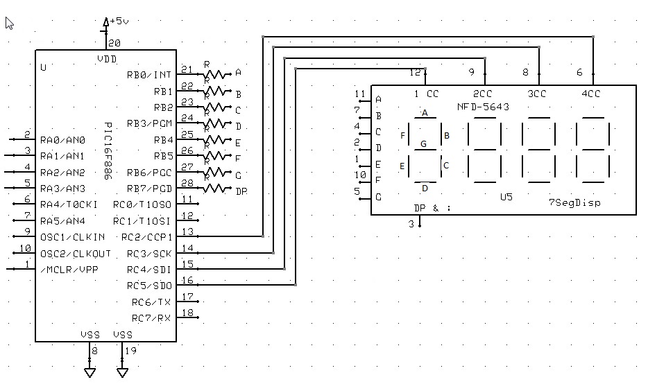
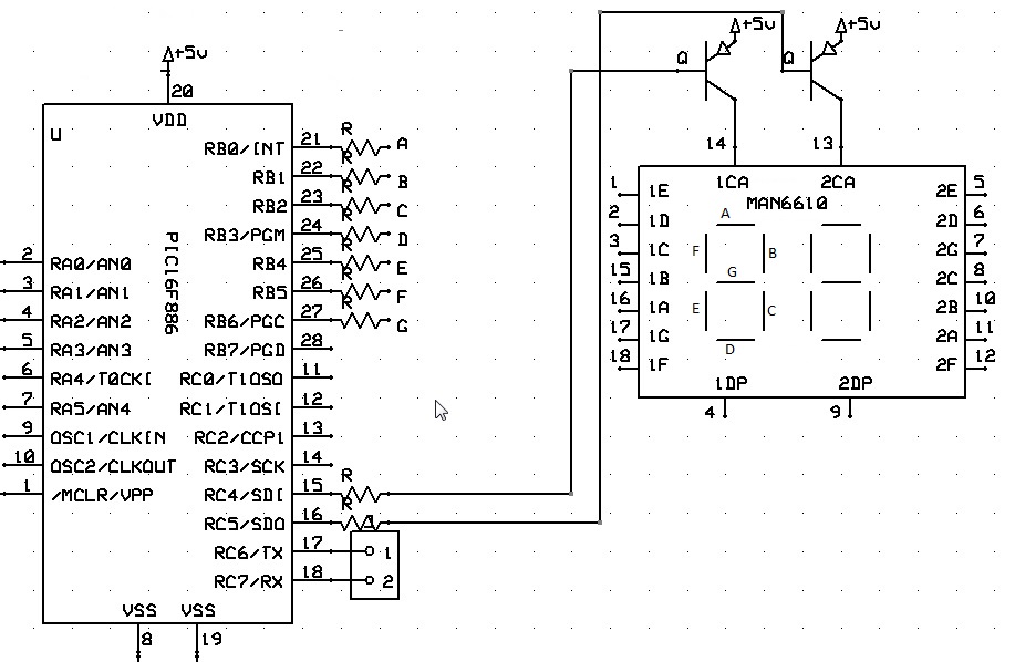
Also, see DisplayChar, DisplayValue
Common Cathode
This is a Common Cathode 7 Segment display example.
No additional configuration is required when using Common Cathnode.
| Constant Name | Controls | Comment |
|---|---|---|
|
Inverts controls for Common Anode displays |
Required for Common Cathode displays |
|
Support PFET or PNP high side driving of the display |
Inverts Common Cathode addressing pin logic for multiplexed displays |
This is a Common Cathode 7 Segment display example.
Example:
'Chip model
#chip 16f1783,8
'Output ports for the 7-segment device
#define DISP_SEG_A PORTC.0
#define DISP_SEG_B PORTC.1
#define DISP_SEG_C PORTC.2
#define DISP_SEG_D PORTC.3
#define DISP_SEG_E PORTC.4
#define DISP_SEG_F PORTC.5
#define DISP_SEG_G PORTC.6
' This is the usage of the SEG_DOT for decimal point support
' An optional third parameter of '1' will turn on the decimal point
' of that digit when using DisplayValue command
#define DISP_SEG_DOT PortC.7
'Select ports for the 7-segment device
#define Disp_Sel_1 PortA.1
#define Disp_Sel_2 PortA.2
#define Disp_Sel_3 PortA.3
dim count as word
dim number as word
Do Forever
For count = 0 to 999
number = count
Num2 = 0
Num3 = 0
If number >= 100 Then
Num3 = number / 100
'SysCalcTempX is the remainder after a division has been completed
number = SysCalcTempX
End if
If number >= 10 Then
Num2 = number / 10
number = SysCalcTempX
end if
Num1 = number
Repeat 10
DisplayValue 1, Num1,1 'Optional third parameter turns on the dp dot on that digit
wait 5 ms
DisplayValue 2, Num2
wait 5 ms
DisplayValue 3, Num3
wait 5 ms
end Repeat
Next
Loop
Also, see 7 Degment Display Overview,DisplayChar, DisplayValue
Common Anode
This is a Common Anode 7 Segment display example.
Additional configuration is required when using Common Anode.
When setting up the 7 segment Common Anode display you MUST use the
7Seg_CommonAnode constant. You can optionally use the 7Seg_HighSide
constant to support PFET or PNP high side driving of the Common Anode
displays as follows:
| Constant Name | Controls | Comment |
|---|---|---|
|
Inverts controls for Common Anode displays |
Required for Common Cathode displays |
|
Support PFET or PNP high side driving of the display |
Inverts Common Cathode addressing pin logic for multiplexed displays |
Example:
'A Common Anode 7 Segment display example using bs250p pfets
'Chip model
#chip 16f1783,8
'support for Common Cathode
#define 7Seg_CommonAnode
'support for pfet or pnp high side drivers
#define 7Seg_HighSide
#define DISP_SEG_A PORTC.0
#define DISP_SEG_B PORTC.1
#define DISP_SEG_C PORTC.2
#define DISP_SEG_D PORTC.3
#define DISP_SEG_E PORTC.4
#define DISP_SEG_F PORTC.5
#define DISP_SEG_G PORTC.6
#define DISP_SEG_DOT PORTC.7
#define Disp_Sel_1 PortA.1
#define Disp_Sel_2 PortA.2
#define Disp_Sel_3 PortA.3
dim count as word
dim number as word
Do Forever
For count = 0 to 999
number = count
Num2 = 0
Num3 = 0
If number >= 100 Then
Num3 = number / 100
'SysCalcTempX is the remainder after a division has been completed
number = SysCalcTempX
End if
If number >= 10 Then
Num2 = number / 10
number = SysCalcTempX
end if
Num1 = number
Repeat 10
DisplayValue 1, Num1, 1 'Optional third parameter turns on the dp on that digit
wait 5 ms
DisplayValue 2, Num2
wait 5 ms
DisplayValue 3, Num3
wait 5 ms
end Repeat
Next
Loop
Also, see 7 Degment Display Overview, DisplayChar, DisplayValue
DisplayValue
Syntax:
DisplayValue (display, data, dot)
Command Availability:
Available on all microcontrollers.
Explanation:
This command will display the given value on a seven segment LED display.
display is the number of the display to use. Up to 4 digits.
data is the value between 0 and F to be shown.
dot is an optional parameter. When it is 1 then the decimal point for that digit is turned on.
The command also support HEX characters in the range between 0x00 and 0x0F (0 to 15). See example two below for usage.
Example 1:
'This program will count from 0 to 99 on two LED displays
#chip 16F819, 8
'See 7 Segment Display Overview for alternate ways of defining Ports
#define DISP_SEG_A PORTB.0
#define DISP_SEG_B PORTB.1
#define DISP_SEG_C PORTB.2
#define DISP_SEG_D PORTB.3
#define DISP_SEG_E PORTB.4
#define DISP_SEG_F PORTB.5
#define DISP_SEG_G PORTB.6
'#define DISP_SEG_DOT PORTB.7 ' Optional DP
#define DISP_SEL_1 PORTA.0
#define DISP_SEL_2 PORTA.1
Do
For Counter = 0 To 99
'Get the 2 digits
Number = Counter
Num1 = 0
If Number >= 10 Then
Num1 = Number / 10
'SysCalcTempX stores remainder after division
Number = SysCalcTempX
End If
Num2 = Number
'Show the digits
'Each DisplayValue will erase the other (multiplexing)
'So they must be called often enough that the flickering
'cannot be seen.
Repeat 500
DisplayValue 1, Num1
Wait 1 ms
DisplayValue 2, Num2
Wait 1 ms
End Repeat
Next
Loop
Example 2:
'This program will count from 0 to 0xff on two LED displays
#chip 16F819, 8
#define DISP_SEG_A PORTB.0
#define DISP_SEG_B PORTB.1
#define DISP_SEG_C PORTB.2
#define DISP_SEG_D PORTB.3
#define DISP_SEG_E PORTB.4
#define DISP_SEG_F PORTB.5
#define DISP_SEG_G PORTB.6
#define DISP_SEL_1 PORTA.0
#define DISP_SEL_2 PORTA.1
#define DISP_SEL_4 PORTA.2
#define DISP_SEL_3 PORTA.3
Do
For Counter = 0 To 0xff
'Get the 2 digits
Number = Counter
Num1 = 0
If Number >= 0x10 Then
Num1 = Number / 0x10
'SysCalcTempX stores remainder after division
Number = SysCalcTempX
End If
Num2 = Number
'Show the digits
'Each DisplayValue will erase the other (multiplexing)
'So they must be called often enough that the flickering
'cannot be seen.
Repeat 500
DisplayValue 1, Num1
Wait 1 ms
DisplayValue 2, Num2
Wait 1 ms
End Repeat
Next
Loop
Also, see 7 Segment Display Overview, DisplayChar, DisplaySegment
DisplayChar
Syntax:
DisplayChar (display, character, dot)
Command Availability:
Available on all microcontrollers.
Explanation:
This command will display the given ASCII character on a seven segment LED display.
display is the number of the display to use. Up to 4 digits.
character is the ASCII character to be shown.
dot is an optional parameter. When it is 1 then the decimal point for that digit is turned on.
This example below is a Common Cathode configuration.
Example 1:
'This program will show " Hello " on a LED display
'The display should be connected to PORTB and the Enable on PORTA.0
#chip 16F877A, 20
#define DISPLAYPORTA PORTB
#define DISP_SEL_1 PORTA.0
Dim Message As String
Message = " Hello "
Do
For Counter = 1 to len(Message)
DisplayChar 1, Message(Counter)
Wait 250 ms
Next
Loop
This is a Common Anode example There are three different methods for port specification Note the ports are specified bit by bit in this case but could be specified like Example 1 See Overview for further explanation.
Example 2:
'This program will show amessage on a LED display
'This is a Dual digit Common anode with driver transistors example
#chip 16F886, 8
'support for Common Anode
#define 7Seg_CommonAnode
'support for pfet or pnp high side drivers
#define 7Seg_HighSide
' Constants
' You need to specify the port settings
#define DISP_SEG_A PORTB.0
#define DISP_SEG_B PORTB.1
#define DISP_SEG_C PORTB.2
#define DISP_SEG_D PORTB.3
#define DISP_SEG_E PORTB.4
#define DISP_SEG_F PORTB.5
#define DISP_SEG_G PORTB.6
#define DISP_SEL_1 PORTC.5
#define DISP_SEL_2 PORTC.4
Dim Message As String
Message = " Happy Holidays "
Do
For Counter = 1 to len(Message)-2
Repeat 50
Displaychar 1, Message(Counter)
wait 3 ms
DisplayChar 2, Message(Counter+1)
wait 3 ms
end Repeat
Wait 100 ms
Next
Loop
Also, see 7 Degment Display Overview, DisplayValue, DisplaySegment
DisplaySegment
Syntax:
DisplayValue (display, data)
Command Availability:
Available on all microcontrollers.
Explanation:
This command will display the given value on a seven segment LED display.
display is the number of the display to use. Up to 4 digits.
data is the value between 0 and 255. Where data is the representation of the segments to be set.
Example
'This program will count from 10 to 0 then fire the rocket!
'The method DisplaySegment 1, smallTCharacter. Sets the 7 segment to the value of 120, see the constant, 120 equates to a small t.
; ----- Configuration
#chip 16F690, 4
; ----- Define Hardware settings
Dir PORTC Out
DIR PORTA.5 out
DIR PORTA.4 out
DIR PORTA.0 out
DIR PORTA.1 out
DIR PORTA.2 in
DIR PORTB.7 out
; ----- Constants
; You need to specify the port settings
#define DISP_SEG_A PORTC.0
#define DISP_SEG_B PORTC.1
#define DISP_SEG_C PORTC.2
#define DISP_SEG_D PORTC.3
#define DISP_SEG_E PORTC.4
#define DISP_SEG_F PORTC.5
#define DISP_SEG_G PORTC.6
#define DECPNT PORTC.7
#define DISP_SEL_1 PORTA.5
#define DISP_SEL_2 PORTA.4
#define DISP_SEL_3 PORTA.1
#define DISP_SEL_4 PORTA.0
#define smallTCharacter 120 'raw character for 't' on 7 segment.
#define sw1 PORTA.2
#define firingPort PORTB.7
; ----- Variables
CountDownValue = 10
; ----- Main body of program commences here.
DECPNT = 1 'Decimal Point off
Main:
' Push number to 7 Segment Display
if sw1 = 0 then goto Countdown
num2 = 1
num3 = 0
cnt = 5
gosub display
goto main
Countdown:
num2 = CountDownValue/10
num3 = CountDownValue%10
cnt = 60
gosub display
If sw1 = 0 then goto hld
if CountDownValue = 0 then
firingPort = 1
cnt = 200
gosub dispfire
firingPort = 0
CountDownValue = 10
goto main
end if
CountDownValue = CountDownValue - 1
goto Countdown
display:
Repeat cnt
DisplaySegment 1, smallTCharacter
wait 5 ms
Displaychar 2, "-"
DisplayValue 3, Num2
wait 5 ms
DisplayValue 4, Num3
wait 5 ms
end Repeat
return
hld:
if sw1 = 0 then goto hld
cnt = 5
gosub Display
if sw1 = 1 then goto hld
goto countdown
DispFire:
Repeat cnt
Displaychar 1, "F"
wait 5 ms
Displaychar 2, "i"
wait 5 ms
Displaychar 3, "r"
wait 5 ms
Displaychar 4, "E"
wait 5 ms
End Repeat
return
end
Also, see 7 Segment Display Overview, DisplayChar
7 Segment Displays - TM1637 4 Digits
Introduction
The TM1637 disaplay module is used for displaying numbers on a keyboard matrix. The matrix of LEDs consists of four 7- segment displays working together.
The TM1637 specification is
-
Two wire interface
-
Eight adjustable luminance levels
-
3.3V/5V interface
-
Supports Four alpha-numeric digits
-
Operating current consumption: 80mA
Why to use TM1637 Display Module?
The TM1637 can be interfaced to any system using only two ports. This is the main reason the module is preferred over other module.
Another reason TM1637 display is preferred is because of its low cost. Although there are other display modules present in the market they cost more.
The module design is robust so it can sustain in tough environments and still can perform its function for a long time. The module consumes low power and can be installed in mobile applications.
How to use TM1637 Display Module?
As mentioned earlier the module communication can only be done using the two pins DIO and CLK respectively. The data is sent to the module or received from the module though these two pins. So the characters to be displayed are sent in the form of serial data through this interface. A typical circuit diagram of display module interface to a controller is shown below.
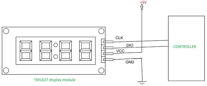
The module can work on +5V regulated power and any higher voltage may lead to permanent damage.
The interface is established as shown in figure above.
All you need to do is connect DIO and CLK to any of GPIO (General Purpose Input Output) pins of controller and establish serial data exchange through programming.
GCBASIC Support
The GCBASIC 7 segment display methods make it easier for GCBASIC programs to display numbers and letters on 7 segment LED displays.
The GCBASIC methods support up to four digit 7 segment display devices, common anode/cathode and inversion of the port logic to support driving the device(s) via a transistor.
Brightness can be set: 8 is display on minimum bright , 15 is display on max bright. Less than 8 is display off.
The TM1637 chip supports the reading of the keyboard matrix however that is not supported in the library.
DataSheets
The datasheets can found here:
English - here.
Chinese - here.
Usage
The following will set the display.
| Constant | Description |
|---|---|
TM1637_CLK |
Must be a bi-directional port. The direction/port setting is managed by the library. |
TM1637_DIO |
Must be a bi-directional port. The direction/port setting is managed by the library. |
Example program
#chip mega328p,16
#include <TM1637a.h>
#define TM1637_CLK PortD.2 ' Arduino Digital_2
#define TM1637_DIO PortD.3 ' Arduino Digital_3
'---- main program --------
TMWrite4Dig (17, 16, 17, 16, 0) 'clear display
wait 2 s
TMWrite4Dig (17, 16, 17, 16, 10,0) '- -
wait 2 s
TMchar_Bright = 10
TMWrite4Dig
Syntax:
TMWrite4Dig (dig1, dig2, dig3, dig4 [, Brightness ], Colon ] ] )
Command Availability:
Available on all microcontrollers.
Explanation:
Command defines each digit (left to right) as 0 to 9 OR 0x00 to 0x0F (15). Additionally 0x10 (16) is a blank, 0x11 (17) is a minus sign, 0x12 (18) is a degree sign, 0x13 (19) is a bracket and 0x14 (20) is a question mark.
Brightness set the brightness (8-15).
Colon turns the colon (only on digit 2) to off (0) or on (1).
TM_Bright
Syntax:
TM_Bright = Brightness
Command Availability:
Available on all microcontrollers.
Explanation:
Brightness sets the brightness for the display with a range of 8 to 15.
Default to 15.
TMDec
Syntax:
TMDec Value [, Options ]
Command Availability:
Available on all microcontrollers.
Explanation:
Value is a word value. Only values from 0 to 9999 can be displayed, values greater than 9999 will be displayed as ----.
Options as follows:
-
0 or omitted, only decimal value will be displayed;
-
1 decimal valur with the leading zeros;
-
2 decimal number with the colon on digit 2;
-
3 decimal number with the colon on digit 2 and the leading zeros.
TMHex
Syntax:
TMHex Value
Command Availability:
Available on all microcontrollers.
Explanation:
Value is a word value. Only values from from 0x0000 to 0xFFFF can be displayed. Non-hex values will be displayed as greater than 9999 will be displayed ??.
TMWriteChar
Syntax:
TMWriteChar ( TMaddr, TMchar )
Command Availability:
Available on all microcontrollers.
Explanation:
TMaddr is 0 , 1 , 2 , 3 (display left to right)
TMchar is a letter from A to Z (default alphabet) or from a to z Siekoo alphabet by Alexander Fakoo, more info at: http://en.fakoo.de/siekoo.html.
You can insert the special characters (blank, -, ) and/or ?).
Character map:
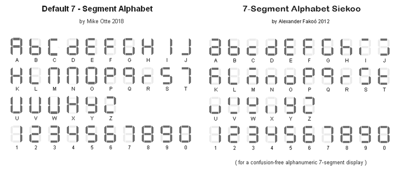
7 Segment Displays - TM1637 6 Digits
Introduction
The TM1637 display module is used for displaying numbers on a keyboard matrix. The matrix of LEDs consists of six 7- segment displays working together.
The TM1637 specification is
-
Two wire interface
-
Eight adjustable luminance levels
-
3.3V/5V interface
-
Supports six alpha-numeric digits
-
Operating current consumption: 80mA
Using the TM1637 Display Module

Why to use TM1637 Display Module?
The TM1637 can be interfaced to any system using only two ports. This is the main reason the module is preferred over other module.
Another reason TM1637 display is preferred is because of its low cost. Although there are other display modules present in the market they cost more.
The module design is robust so it can sustain in tough environments and still can perform its function for a long time. The module consumes low power and can be installed in mobile applications.
How to use TM1637 Display Module?
As mentioned earlier the module communication can only be done using the two pins DIO and CLK respectively. The data is sent to the module or received from the module though these two pins. So the characters to be displayed are sent in the form of serial data through this interface. A typical circuit diagram of display module interface to a controller is shown below.
The module can work on +5V regulated power and any higher voltage may lead to permanent damage.
The interface is established as shown in figure above.
All you need to do is connect DIO and CLK to any of GPIO (General Purpose Input Output) pins of controller and establish serial data exchange through programming.
GCBASIC Support
The GCBASIC 7 segment display methods make it easier for GCBASIC programs to display numbers and letters on 7 segment LED displays.
The GCBASIC methods supports six 7 segment display devices, common anode/cathode and inversion of the port logic to support driving the device(s) via a transistor.
Brightness can be set: 8 is display on minimum bright , 15 is display on max bright. Less than 8 is display off.
The TM1637 chip supports the reading of the keyboard matrix however that is not supported in the library.
DataSheets
The datasheets can found here:
English - here.
Chinese - here.
Usage
The following will set the display.
| Constant | Description |
|---|---|
TM1637_CLK |
Must be a bi-directional port. The direction/port setting is managed by the library. |
TM1637_DIO |
Must be a bi-directional port. The direction/port setting is managed by the library. |
Example program
#chip mega328p,16
#include <TM1637a.h>
#define TM1637_CLK PortD.2 ' Arduino Digital_2
#define TM1637_DIO PortD.3 ' Arduino Digital_3
'---- main program --------
TMWrite6Dig (17, 16, 17, 16, 0) 'clear display
wait 2 s
TMWrite6Dig (17, 16, 17, 16, 10,0) '- -
wait 2 s
TMchar_Bright = 10
TMWrite6Dig
Syntax:
TMWrite6Dig (dig1, dig2, dig3, dig4, dig5, dig6, Brightness, Point)
Command Availability:
Available on all microcontrollers.
Explanation:
Command defines each digit (left to right) as 0 to 9 or 0x00 to 0x0F (15). Additionally 0x10 (16) is a blank, 0x11 (17) is a minus sign, 0x12 (18) is a degree sign, 0x13 (19) is a bracket and 0x14 (20) is a question mark.
Brightness set the brightness (8-15).
Colon turns the colon (only on digit 2) to off (0) or on (1).
TM_Bright
Syntax:
TM_Bright = Brightness
Command Availability:
Available on all microcontrollers.
Explanation:
Brightness sets the brightness for the display with a range of 8 to 15. Default to 15.
TM_Bright must be defined before the first use the commands: TMDec, TMHex or TMWriteChar, to set the brightness of the characters (8-15), without this, the display will be blank.
TMDec
Syntax:
TMDec Value [, Options ]
Command Availability:
Available on all microcontrollers.
Explanation:
Value is a word value. Only values from 0 to 9999 can be displayed, values greater than 9999 will be displayed as ----.
Options as follows:
-
0 or omitted, only decimal value will be displayed;
-
1 decimal valur with the leading zeros;
-
2 decimal number with the colon on digit 2;
-
3 decimal number with the colon on digit 2 and the leading zeros.
TMHex
Syntax:
TMHex Value
Command Availability:
Available on all microcontrollers.
Explanation:
Value is a word value. Only values from from 0x0000 to 0xFFFF can be displayed. Non-hex values will be displayed as greater than 9999 will be displayed ??.
TMWriteChar
Syntax:
TMWriteChar ( TMaddr, TMchar )
Command Availability:
Available on all microcontrollers.
Explanation:
TMaddr is 0 , 1 , 2 , 3 4, 5 (display left to right)
TMchar is a letter from A to Z (default alphabet) or from a to z Siekoo alphabet by Alexander Fakoo, more info at: http://en.fakoo.de/siekoo.html.
You can insert the special characters (blank, -, ) and/or ?).
Character map:
TM_Point
Syntax:
TM_Point = (Point)
Command Availability:
Available on all microcontrollers.
Explanation:
Must be defined before use the command TMDec to set the decimal point(s)
Rules for decimal points
You can use the TM_Point and TMWrite6dig commands to turn on one or more decimal points. This is achieved with an 8-bit binary number, with the leftmost bit (MSB) representing the 1st decimal point, the next the 2nd, and so on. The state of the last two bits is ignored because it is only 6 digits.
Examples:
• binary number 0B01010000 (decimal 80) switch on decimal point on digits 2 and 4. • number 0 switch off all digital points • 255 (0B11111111) switch all on.
One Wire Devices
This is the One Wire Devices section of the Help file. Please refer the sub-sections for details using the contents/folder view.
DS18B20
The DS18B20 is a 1-Wire digital temperature sensor from Maxim IC.
The sensor reports degrees C with 9 to 12-bit precision from -55C to 125C (+/- 0.5C).
Each sensor has a unique 64-Bit Serial number etched into it. This allows for a number of sensors to be used on one data bus. This sensor is used in many data-logging and temperature control projects.
Reading the temperature from a DS18B20 takes up to 750ms(max).
To use the DS18B20 driver the following is required to added to the GCBASIC source file.
#include <DS18B20.h>
Note the GCBASIC commands do not work with the older DS1820 or DS18S20 as they have a different internal resolution.
These commands are not designed to be used with parasitically powered DS18B20 sensors.
| Command | Usage | Returns |
|---|---|---|
ReadDigitalTemp |
Returns two global variables. As follows:
|
Byte variables:
String variable: |
ReadTemp |
The temperature is read back in whole degree steps, and the sensor operates from -55 to + 125 degrees Celsius.;  Note that bit 7 is 0 for positive temperature values and 1 for negative values (ie negative values will appear as 128 + numeric value). |
Word variable via the ReadTemp() function |
ReadTemp12 |
The temperature is read back as the raw 12 bit data into a word variable (0.0625 degree resolution).;  The user must interpret the data through mathematical manipulation. See the DS18B20 datasheet for more information on the 12 bit temperature/data information construct. |
Word variable via the ReadTemp12() function |
For more help, see ReadDigitalTemp, ReadTemp or ReadTemp12
ReadDigitalTemp
Syntax:
ReadDigitalTemp
Command Availability:
Available on all microcontrollers.
Explanation:
Return the value of the sensor in two global variables. The following two lines must be included in the GCBASIC source file.
#include <DS18B20.h>
#define DQ PortC.3 ; change port configuration as required
This method returns whole part of the sensor value in the byte variable DSint, the method also returns decimal part of the sensor value in the byte variable DSdec.
Example:
'Chip Settings. Assumes the development board with with a 16F877A
#chip 16F877A,1
*#include <DS18B20.h>*
'Use LCD in 4 pin mode and define LCD pins
#define LCD_IO 4
#define LCD_WIDTH 20 ;specified lcd width for clarity only. 20 is the default width
#define LCD_RW PORTE.1
#define LCD_RS PORTE.0
#define LCD_Enable PORTE.2
#define LCD_DB4 PORTD.4
#define LCD_DB5 PORTD.5
#define LCD_DB6 PORTD.6
#define LCD_DB7 PORTD.7
' DS18B20 port settings
#define DQ PortC.3
do forever
ReadDigitalTemp
' Display the integer value of the sensor on the LCD
cls
print "Temp"
locate 0,8
print DSInt
print "."
print DSdec
print chr(223)+"C"
wait 2 s
loop
ReadTemp
Syntax:
byte_var = ReadTemp
Command Availability:
Available on all microcontrollers.
Explanation:
ReadTemp is a function that returns the raw value of the sensor. The following two lines must be included in the GCBASIC source file.
#include <DS18B20.h>
#define DQ PortC.3 ; change port configuration as required
ReadTemp reads the sensor and stores in output variable. The conversion takes up to 750ms. Readtemp carries out a full 12 bit conversion and then rounds the result to the nearest full degree Celsius.
To read the full 12 bit value of the sensor use the readtemp12 command.
The temperature is read back in whole degree steps, and the sensor operates from -55 to + 125 degrees Celsius. Note that bit 7 is 0 for positive temperature values and 1 for negative values (ie negative values will appear as 128 + numeric value).
Note the Readtemp command does not work with the older DS1820 or DS18S20 as they have a different internal resolution. This command is not designed to be used with parasitically powered DS18B20 sensors, the 5V pin of the sensor must be connected.
Example:
'Chip Settings. Assumes the development board with with a 16F877A
#chip 16F877A,1
#include <DS18B20.h>
'Use LCD in 4 pin mode and define LCD pins
#define LCD_IO 4
#define LCD_WIDTH 20 ;specified lcd width for clarity only. 20 is the default width
#define LCD_RW PORTE.1
#define LCD_RS PORTE.0
#define LCD_Enable PORTE.2
#define LCD_DB4 PORTD.4
#define LCD_DB5 PORTD.5
#define LCD_DB6 PORTD.6
#define LCD_DB7 PORTD.7
' DS18B20 port settings
#define DQ PortC.3
ccount = 0
CLS
do forever
' The function readtemp returns the integer value of the sensor
DSdata = readtemp
' Display the integer value of the sensor on the LCD
locate 0,0
print hex(ccount)
print " Ceil"
locate 0,8
print DSdata
print chr(223)+"C"
wait 2 s
ccount++
loop
ReadTemp12
Syntax:
byte_var = ReadTemp12
Command Availability:
Available on all microcontrollers.
Explanation:
ReadTemp12 is a function that returns the raw value of the sensor. The following two lines must be included in the GCBASIC source file.
#include <DS18B20.h>
#define DQ PortC.3 ; change port configuration as required
Reads sensor and stores in output variable. The conversion takes up to 750ms. Readtemp12 carries out a full 12 bit conversion.
This command is for advanced users only. For standard ‘whole degree’ data use the Readtemp command.
The temperature is read back as the raw 12 bit data into a word variable (0.0625 degree resolution). The user must interpret the data through mathematical manipulation. See the DS18B20 datasheet for more information on the 12 bit temperature/data information construct.
The function readtemp12 does not work with the older DS1820 or DS18S20 as they have a different internal resolution. This command is not designed to be used with parasitically powered DS18B20 sensors, the 5V pin of the sensor must be connected.
Example:
'Chip Settings. Assumes the development board with with a 16F877A
#chip 16F877A,1
#include <DS18B20.h>
'Use LCD in 4 pin mode and define LCD pins
#define LCD_IO 4
#define LCD_WIDTH 20 ;specified lcd width for clarity only. 20 is the default width
#define LCD_RW PORTE.1
#define LCD_RS PORTE.0
#define LCD_Enable PORTE.2
#define LCD_DB4 PORTD.4
#define LCD_DB5 PORTD.5
#define LCD_DB6 PORTD.6
#define LCD_DB7 PORTD.7
; ----- DS18B20 port settings
#define DQ PortC.3
; ----- Variables
Dim TempC_100 as word ' a variabler to handle the temperature calculations
Dim CCOUNT, SIGNBIT, WHOLE, FRACT, DIG as Byte
Dim TempC_100 as word ' a variable to handle the temperature calculations
ccount = 0
CLS
do forever
'Display the integer and decimal value of the sensor on the LCD
' The function readtemp12 returns the raw value of the sensor.
' The sensor is read as a 12 bit value. Each unit equates to 0.0625 of a degree
DSdata = readtemp12
SignBit = DSdata / 256 / 128
If SignBit = 0 Then goto Positive
' its negative!
DSdata = ( DSdata # 0xffff ) + 1 ' take twos comp
Positive:
' Convert value * 0.0625. Mulitple value by 6 then add result to multiplication of the value with 25 then divide result by 100.
TempC_100 = DSdata * 6
DSdata = ( DSdata * 25 ) / 100
TempC_100 = TempC_100 + DSdata
Whole = TempC_100 / 100
Fract = TempC_100 % 100
If SignBit = 0 Then goto DisplayTemp
Print "-"
DisplayTemp:
locate 1,0
print hex(ccount)
print " Real"
locate 1,8
print str(Whole)
print "."
' To ensure the decimal part is two digits
Dig = Fract / 10
print Dig
Dig = Fract % 10
print Dig
print chr(223)
print "C"
wait 2 s
ccount++
loop
DS18B20SetResolution
Syntax:
For Single Channel/Device only. The method assumes a single DS18B20 device on the OneWire bus.
DS18B20SetResolution ( [DS18B20SetResolution_CONTSTANT] )
Command Availability:
Available on all microcontrollers.
Explanation:
Set the DS18B20 operating resolution. The configuration register of the DS18B20 allows the user to set the resolution of the temperature-to-digital conversion to 9, 10, 11, or 12 bits. This method set the operating resolution to either 9, 10, 11, or 12 bits.
Calling the method with no parameter will set the operating resolution of the DS18B20 to 12 bits. See example 3 below.
Constants
| CONSTANT | Operating resolution | Temprature resolution |
|---|---|---|
DS18B20_TEMP_9_BIT |
9 bits |
0.5c |
DS18B20_TEMP_10_BIT |
10 bits |
0.25c |
DS18B20_TEMP_11_BIT |
11 bits |
0.125c |
DS18B20_TEMP_12_BIT |
12 bits |
0.0625c |
Example Usage 1
The follow example sets the operating resolution of the DS18B20 to 12 bits.
#include <DS18B20.h>
#define DQ PortC.3 ; change port configuration as required
DS18B20SetResolution ( DS18B20_TEMP_12_BIT )
Example Usage 2
The follow example sets the operating resolution of the DS18B20 to 9 bits.
#include <DS18B20.h>
#define DQ PortC.3 ; change port configuration as required
DS18B20SetResolution ( DS18B20_TEMP_9_BIT )
Example Usage 3
The follow example sets the operating resolution of the DS18B20 to the default value of 12 bits.
#include <DS18B20.h>
#define DQ PortC.3 ; change port configuration as required
DS18B20SetResolution ( )
Working Example Program
The following program will display the temperature on a serial attached LCD.
Change the DS18B20SetResolution () method to set the resolution of a specific setting.
You may need to change the chip, edit/remove PPS, and/or the change LCD settings to make this program work with your configuration.
#chip 16f18313
#config MCLR=ON
#option Explicit
#include <ds18b20.h>
'Generated by PIC PPS Tool for GCBASIC
'PPS Tool version: 0.0.6.1
'PinManager data: v1.79.0
'Generated for 16f18313
'
'Template comment at the start of the config file
'
#startup InitPPS, 85
#define PPSToolPart 16f18313
Sub InitPPS
'Module: EUSART
RA5PPS = 0x0014 'TX > RA5
End Sub
'Template comment at the end of the config file
'USART settings for USART1
#define USART_BAUD_RATE 115200
#define USART_TX_BLOCKING
#define USART_DELAY OFF
#define LCD_IO 107 'K107
#define LCD_WIDTH 20 ;specified lcd width for clarity only. 20 is the default width
; ----- Constants
' DS18B20 port settings
#define DQ RA4
; ----- Variables
dim TempC_100 as LONG ' a variabler to handle the temperature calculations
Dim DSdata,WHOLE, FRACT, DIG as word
Dim CCOUNT, SIGNBIT as Byte
; ----- Main body of program commences here.
ccount = 0
CLS
print "GCBasic 2021"
locate 1,0
print "DS18B20 Demo"
wait 2 s
CLS
DS18B20SetResolution ( DS18B20_TEMP_12_BIT )
do forever
' The function readtemp returns the integer value of the sensor
DSdata = readtemp
' Display the integer value of the sensor on the LCD
locate 0,0
print hex(ccount)
print " Ceil"
locate 0,8
print DSdata
print chr(223)+"C"
' Display the integer and decimal value of the sensor on the LCD
' The function readtemp12 returns the raw value of the sensor.
' The sensor is read as a 12 bit value therefore each unit equates to 0.0625 of a degree
DSdata = readtemp12
SignBit = DSdata / 256 / 128
If SignBit = 0 Then goto Positive
' its negative!
DSdata = ( DSdata # 0xffff ) + 1 ' take twos comp
Positive:
' Convert value * 0.0625 by factorisation
TempC_100 = DSdata * 625
Whole = TempC_100 / 10000
Fract = TempC_100 % 10000
If SignBit = 0 Then goto DisplayTemp
Print "-"
DisplayTemp:
Locate 3,0
Print Whole
Print "."
Print leftpad( str(Fract),4,"0")
wait 2 s
ccount++
loop
Serial Communications
This is the Serial Communications section of the Help file. Please refer the sub-sections for details using the contents/folder view.
RS232 (software)
This is the Software Serial Communications section of the Help file. Please refer the sub-sections for details using the contents/folder view.
RS232 Software Overview
Introduction:
These routines allow the microcontroller to send and receive RS232 data.
All functions are implemented using software, so no special hardware is required on the microcontroller. However, if the microcontroller has a hardware serial module (usually referred to as UART or USART), and the serial data lines are connected to the appropriate pins, the hardware routines should be used for smaller code, improved reliability and higher baud rates.
Relevant Constants:
These constants are used to control settings for the RS232 serial
communication routines. To set them, place a line in the main program
file that uses #define to assign a value to the particular constant.
| Constant Name/s | Controls | Default Value |
|---|---|---|
|
These are used to define the commands used to send a low (0) bit on serial channels A, B and C respectively. |
No Default |
|
These are used to define the commands used to send a high (1) bit on serial channels A, B and C respectively. |
No Default |
|
The condition that is true when a low bit is being received |
|
|
The condition that is true when a high bit is being received |
|
InitSer
Syntax:
InitSer channel, rate, start, data, stop, parity, invert
Command Availability:
Available on all microcontrollers.
Explanation:
This command will set up the serial communications. The parameters are as follows:
channel is 1, 2 or 3, and refers to the I/O ports that are used for
communication.
rate is the bit rate, which is given by the letter r and then the
desiredrate in bps. Acceptable units are r300, r600, r1200, r2400,
r4800, r9600 and r19200.
start gives the number of start bits, which is usually 1. To make
the microcontroller wait for the start bit before proceeding with the receive, add
128 to start. (Note: it may be desirable to use the WaitForStart
constant here.)
data tells the program how many data bits are to be sent or received.
In most situations t his is 8, but it can range between 1 and 8,
inclusive.
stop is the number of stop bits. If start bit 7 is on, then this
number will be ignored.
parity refers to a system of error checking used by many devices. It
can be odd (in which there must always be an odd number of high bits),
even (where the number of high bits must always be even), or none (for
systems that do not use parity).
invert can be either "normal" or "invert". If it in "invert", then
high bits will be changed to low, and low to high.
Example:
Please refer to SerSend for an example of InitSer
For more help, see RS232 Software Overview
SerSend
Syntax:
SerSend channel, data
Command Availability:
Available on all microcontrollers.
Explanation:
This command will send a byte given by data using the RS232 channel
referred to as channel according to the rules set using InitSer.
Example:
'This program will send a byte using PORTB.2, the value of which
'depends on whether a button is pressed. This can be used with the example for SerReceive.
#chip 16F819, 8
#define RS232Out PORTB.2
#define RS232In PORTB.1
Dir RS232Out Out
Dir RS232In In
'Config Software-UART
#define SendAHigh Set RS232Out ON
#define SendALow Set RS232Out OFF
#define RecAHigh Set RS232In ON
#define RecALow Set RS232In OFF
Dir Button In
InitSer 1, r9600, 1+WaitForStart, 8, 1, none, normal
Do
If Button = On Then Temp = 100
If Button = Off Then Temp = 0
SerSend 1, Temp
Wait 100 ms
Loop
For more help, see RS232 Software Overview, InitSer
SerReceive
Syntax:
SerReceive channel, output
Command Availability:
Available on all microcontrollers.
Explanation:
This command will read a byte from the RS232 channel given by
channel according to the rules set using InitSer, and store the
received byte in the variable output.
Example:
'This program will read a byte from PORTB.2, and set the LED on if
'the byte is more than 50. This can be used with the SerSend
'example program.
#chip 16F88, 8
#define RecAHigh PORTB.2 ON
#define RecALow PORTB.2 OFF
#define LED PORTB.0
Dir PORTB.0 Out
Dir PORTB.2 In
InitSer 1, r9600, 1 + WaitForStart, 8, 1, none, normal
Do
SerReceive 1, Temp
If Temp <= 50 Then Set LED Off
If Temp > 50 Then Set LED On
Loop
For more help, see RS232 Software Overview, InitSer
SerPrint
Syntax:
SerPrint channel, value
Command Availability:
Available on all microcontrollers.
Explanation:
SerPrint is used to send a value over the serial connection. value can
be a string, integer, long, word or byte.
channel is the serial connection to send data through (1 | 2 |3 ).
SerPrint will not send any new line characters. If the chip is sending
to a terminal, these commands should follow SerPrint.
SerSend channel, 13
SerSend channel, 10
Example:
'This program will display any values received over the serial
'connection. If "pot" is received, the value of the analog sensor
'will be sent.
'Chip settings
#chip 18F2525, 8
'LCD settings
#define LCD_IO 4
#define LCD_WIDTH 20 ;specified lcd width for clarity only. 20 is the default width
#define LCD_RS PORTC.7
#define LCD_RW PORTC.6
#define LCD_Enable PORTC.5
#define LCD_DB4 PORTC.4
#define LCD_DB5 PORTC.3
#define LCD_DB6 PORTC.2
#define LCD_DB7 PORTC.1
'Serial settings
#define RS232Out PORTB.0
#define RS232In PORTB.1
'Set pin direction
Dir RS232Out Out
Dir RS232In In
'Config Software-UART
#define SendAHigh Set RS232Out ON
#define SendALow Set RS232Out OFF
#define RecAHigh Set RS232In ON
#define RecALow Set RS232In OFF
set RS232Out On
Do
'Potentiometer
#define POT_PORT PORTA.0
#define POT_AN AN0
'Set pin direction
Dir POT_PORT In
'Create buffer variables to store received messages
Dim Buffer As String
Dim OldBuffer As String
BufferSize = 0
'Set up serial connection
InitSer 1, r9600, 1 + WaitForStart, 8, 1, none, invert
'Show test messages
Print "Serial Tester"
Wait 1 s
SerPrint 1, "GCBASIC RS232 Test"
SerSend 1, 13
SerSend 1, 10
Wait 1 s
'Main loop
'Get a byte from the terminal
SerReceive 1, Temp
'If Enter key was pressed, deal with buffer contents
If Temp = 13 Then
Buffer(0) = BufferSize
'Try to execute commands in buffer
If Not ExecCommand (Buffer) Then
'Show message on bottom line, last message on top.
CLS
Print OldBuffer
Locate 1, 0
Print Buffer
'Store the message for next time
OldBuffer = Buffer
End If
BufferSize = 0
End If
'Backspace code, delete last character in buffer
If Temp = 8 Then
If BufferSize > 0 Then BufferSize -= 1
End If
'Received ASCII code between 32 and 127, add to buffer
If Temp >= 32 And Temp <= 127 Then
BufferSize += 1
Buffer(BufferSize) = Temp
End If
Loop
'Takes a sensor reading and sends it to terminal
Sub SendSensorReading
SerPrint 1, "Sensor Reading: "
SerPrint 1, ReadAD10(POT_AN)
SerSend 1, 13
SerSend 1, 10
End Sub
'Will check the buffer for a command
'If command found, run it and return true
'If not, return false
Function ExecCommand (CmdIn As String)
ExecCommand = False
'If received command is "pot", show potentiometer value
If CmdIn = "pot" Then
SendSensorReading
ExecCommand = True
End If
End Function
For more help, see RS232 Software Overview
RS232 (software optimised)
This is the Software Serial Communications section of the Help file. Please refer the sub-sections for details using the contents/folder view.
RS232 Software Overview - Optimised
Introduction:
These routines allow the microcontroller to send and receive RS232 data.
SoftSerial is a library for the GCBASIC compiler and works on AVR and PIC microcontrollers. These routines allow the microcontroller to send and receive RS232 data. All functions are implemented using software, so no special hardware is required on the microcontroller. SoftSerial uses ASM routines for minimal overhead. If the microcontroller has a hardware serial module (usually referred to as UART or USART) the hardware routines can be used too.
Features
-
3 independent channels Ser1… , Ser2… , Ser3…
-
I/O pins user configurable
-
polarity can be inverted
-
freely adjustable baud rate
-
maximum baudrate depends on MCU speed
-
PIC@ 1Mhz 9600 baud
-
PIC@ 4Mhz 38400 baud
-
PIC@ 8Mhz 64000 baud
-
PIC@16Mhz 128000 baud
-
AVR@ 1Mhz 28800 baud
-
AVR@ 8Mhz 115200 baud
-
AVR@16Mhz 460800 baud
-
-
5 - 8 data bits
-
1 or 2 stop bits
-
parity bit not supported
Relevant Constants:
These constants are used to control settings for the RS232 serial
communication routines. To set them, place a line in the main program
file that uses #define to assign a value to the particular constant.
| Constant Name/s | Controls | Valid Values | Default value |
|---|---|---|---|
SER1_TXPORT, SER2_TXPORT, SER3_TXPORT |
These are used to define the port for sending on serial channels 1, 2 and 3 respectively. Note, that we also have to define a PortPin (see next line). It is not necessary to define this, if we want to receive only. Sample: #define SER1_TXPORT PortB |
PORTA - PORTx |
No default defined. An appropiate constant must be defined. |
SER1_TXPIN, SER2_TXPIN, SER3_TXPIN |
These are used to define the pin (the corresponding bit) for sending on serial channels 1, 2 and 3 respectively. Sample: #define SER1_TXPIN 0 |
0 - 7 |
No default defined. An appropiate constant must be defined to enable the TX port. |
SER1_RXPORT, SER2_RXPORT, SER3_RXPORT |
These are used to define the port for receiving on serial channels 1, 2 and 3 respectively. Note, that we also have to define a PortPin (see next line). It is not necessary to define this, if we want to receive only. Sample: #define SER1_RXPORT PortA |
PORTA - PORTx |
No default defined. An appropiate constant must be defined to enable the TX port. |
SER1_RXPIN, SER2_RXPIN, SER3_RXPIN |
These are used to define the pin (the corresponding bit) for receiving on serial channels 1, 2 and 3 respectively. It is not necessary to define this, if we want to send only. Sample: #define SER1_RXPIN 5 |
0 - 7 |
No default defined. An appropiate constant must be defined to enable the RX port. |
SER1_BAUD, SER2_BAUD, SER3_BAUD |
These are used to define the baudrate for sending and receiving on serial channels 1, 2 and 3 respectively. It is not necessary to define this, if we want to send only. Sample: #define SER1_BAUD 19200 |
75 - 512000 |
No default defined. An appropiate constant must be defined to enable the RX port. |
SER1_DATABITS, SER2_DATABITS, SER3_DATABITS |
These are used to define the databits for sending and receiving on serial channels 1, 2 and 3 respectively. Sample: #define SER1_DATABITS 7 |
5 - 8 |
Optional Default = 8 |
SER1_STOPBITS, SER2_STOPBITS, SER3_STOPBITS |
These are used to define the stopbits for sending and receiving on serial channels 1, 2 and 3 respectively. Sample: #define SER1_STOPBITS 2 |
1, 2 |
Optional Default = 1 |
SER1_INVERT, SER2_INVERT, SER3_INVERT |
These are used to define the polarity for sending and receiving on serial channels 1, 2 and 3 respectively. If it is "On", then high bits will be changed to low, and low to high. This is useful for connection to a PCs native serial port or USB-serial converters with MAX232. Sample: #define SER1_INVERT On |
On, Off |
Optional Default = Off |
SER1_RXNOWAIT, SER2_RXNOWAIT, SER3_RXNOWAIT |
These are used to define, if SerNReceive waits for the startbits when receiving on serial channels 1, 2 and 3 respectively. If it is "On", then SerNReceive does not wait for the startbits edge, but directly reads the serial data. Also the time for delaying the startbit is shortened. This is useful when calling SerNReceive from an Interrupt-Service-Routine. Sample: #define SER1_RXNOWAIT On |
On, Off |
Optional Default = Off |
SER1_TXDELAY, SER2_TXDELAY, SER3_TXDELAY |
These are used to define, if SerNSend waits for the defined milliseconds after sending a byte of serial data. This is useful when using SerNPrint or SerNSend to a serial device that needs processing time between bytes. |
1..255 |
Optional Default =0 |
SER1_TXDELAYms, SER2_TXDELAYms, SER3_TXDELAYms |
These are used to define, if SerNSend waits for the defined milliseconds after sending a byte of serial data. This is useful when using SerNPrint or SerNSend to a serial device that needs processing time between bytes. Same functionality as SERn_TXDELAY |
1..255 |
Optional Default =0 |
SER1_TXDELAYus, SER2_TXDELAYus, SER3_TXDELAYus |
These are used to define, if SerNSend waits for the defined nanoseconds after sending a byte of serial data. This is useful when using SerNPrint or SerNSend to a serial device that needs processing time between bytes. |
1..255 |
Optional Default =0 |
SerNSend
Ser1Send, Ser2Send, Ser3Send
Syntax:
Ser1Send data
Ser2Send data
Ser3Send data
Command Availability:
Available on all microcontrollers.
Explanation:
This command will send a byte given by data using the channel referred to as Ser1.. , Ser2… , Ser3… according to the rules set by the related defines.
Example:
'This program will send one byte using PORTA.5
; ----- Configuration
#chip 12F1501, 1
; ----- Include library
#include <SoftSerial.h>
; ----- Config Serial UART for sending:
#define SER1_BAUD 9600 ; baudrate must be defined
#define SER1_TXPORT PORTA ; I/O port (without .bit) must be defined
#define SER1_TXPIN 5 ; portbit must be defined
; ----- Main body of program commences here.
Ser1Send 88 'send one byte (88 = X)
Exposed in SoftSerial.h authored by Frank Steinberg
SerNPrint
Ser1Print, Ser2Print, Ser3Print
Syntax:
Ser1Print value
Ser2Print value
Ser3Print value
Command Availability:
Available on all microcontrollers.
Explanation:
This command will send a value using the channel referred to as Ser1.. , Ser2… , Ser3… according to the rules set by the related defines. value can be a string, integer, long, word or byte.
Example:
'This program will send text and an icrementing value using PORTB.1
; ----- Configuration
#chip 16F886, 16
#option Explicit
; ----- Include library
#include <SoftSerial.h>
; ----- Config Serial UART :
#define SER1_BAUD 115200 ; baudrate must be defined
; Config I/O ports for transmitting:
#define SER1_TXPORT PORTB ; I/O port (without .bit) must be defined
#define SER1_TXPIN 1 ; portbit must be defined
; ----- Variables
Dim xx As Word
xx = 1000
; ----- Main body of program commences here.
Do Forever
Wait 1 s 'time to enjoy the result
Ser1Send 13 'new line in Terminal
Ser1Send 10
Ser1Print "Software-UART: " 'send a text
Ser1Print xx 'send the value of xx
xx += 1
Loop
Exposed in SoftSerial.h authored by Frank Steinberg
SerNReceive
Ser1Receive, Ser2Receive, Ser3Receive
Syntax:
bytevar = Ser1Receive
bytevar = Ser2Receive
bytevar = Ser3Receive
Command Availability:
Available on all microcontrollers.
Explanation:
This function will read a byte using the channel referred to as Ser1.. , Ser2… , Ser3… according to the rules set by the related defines. The received byte is stored in the variable bytevar. By default the function waits for the startbit impulse edge before executing the following commands. See the sample files how to realize timeout-functionality or interrupt-driven receiving.
Example:
'This program will receive bytes on PORTB.0 and send back using PORTB.1
; ----- Configuration
#chip 16F886, 16
#option Explicit
; ----- Include library
#include <SoftSerial.h>
; ----- Config Serial UART :
#define SER1_BAUD 115200 ; baudrate must be defined
#define SER1_DATABITS 7 ; databits optional (default = 8)
#define SER1_STOPBITS 2 ; stopbits optional (default = 1)
#define SER1_INVERT Off ; inverted polarity optional (default = Off)
; Config I/O ports for transmitting:
#define SER1_TXPORT PORTB ; I/O port (without .bit) must be defined
#define SER1_TXPIN 1 ; portbit must be defined
; Config I/O ports for receiving:
#define SER1_RXPORT PORTB ; I/O port (without .bit) must be defined
#define SER1_RXPIN 0 ; portbit must be defined
#define SER1_RXNOWAIT Off ; don't wait for stopbit optional (default = Off)
; ----- Variables
Dim RecByte As Byte
; ----- Main body of program commences here.
Wait 1 Ms 'delay to prevent garbage if sending too quick after init
Ser1Send 10 'new line in Terminal
Ser1Send 13 '
Ser1Print "Please send a byte!"
Do Forever
RecByte = Ser1Receive 'receive one byte - wait until detecting startbit
Ser1Send 13 'new line in Terminal
Ser1Send 10 '
Ser1Print "You sent: " 'send a text
Ser1Send RecByte 'send the sign representing the byte
Loop
Exposed in SoftSerial.h authored by Frank Steinberg
RS232 (hardware)
This is the RS232 (hardware) section of the Help file. Please refer the sub-sections for details using the contents/folder view.
RS232 Hardware Overview
Introduction
GCBASIC support programs to communicate easily using RS232.
GCBASIC included microcontroller hardware-based serial routines are intended for use on microcontrollers with built in serial communications modules - normally referred to in datasheets as USART or UART modules. Check the microcontroller data sheet for the defined transmit and receive (TX/Rx) pins. Make sure your program sets the Tx pin direction to Out and the Rx pin direction to In respectively. If the RS232 lines are connected elsewhere, or the microcontroller has no USART module, then the GCBASIC software based RS232 routines must be used.
Initialization of the USART module is handled automatically from your program by defining the chip, speed, and the baudrate. The baudrate generator values are calculated and set, usart is set to asynchronous, usart is enabled , the receive and transmit are enabled. See the table below.
Example:
#chip mega328p, 16 #define USART_BAUD_RATE 9600 #define USART_TX_BLOCKING
Command Availability:
Available on all microcontrollers with a USART or UART module.
Microchip PIC supports USART1 and 2.
Atmel AVR supports USART 1,2,3 and 4.
The following table explains the methods that can be implemented when using the GCBASIC serial routines.
Commands:
| Command | Parameters | Example |
|---|---|---|
Serially print numbers (byte, word, long) or strings. |
||
|
Number_constant or number_variable or string [,optional usart address] The optional usart address is microcontroller specific buy can be 1, 2, 3 or 4. |
This subroutine prints a variable value to usart 1. No additional parameter for the usart number is used.
To print a variable value to usart 2. Note the additional parameter for the usart address.
|
Serially receive ascii number characters and assign to a word variable. |
||
|
Number_variable [,optional usart address] The optional usart address is microcontroller specific buy can be 1, 2, 3 or 4. |
This subroutine ensures that the characters received are numbers. When a carriage return (CR or ASCII code 13) is received this signifies the end of the character stream. Defaults to usart1. To receive number characters use.
To receive number characters via usart2 use.
|
Serially receive characters as a string. |
||
|
User_string_variable [,optional usart address] The optional usart address is microcontroller specific buy can be 1, 2, 3 or 4. |
This subroutine ensures that the characters treated as a string. When a carriage return (CR or ASCII code 13) is received this signifies the end of the character stream. GCBASIC will determine the default buffering size for strings. See here for more help on string sizes. Defaults to usart1. To receive a string use. To a string via usart2 use. |
Serially receive a character using a subroutine. |
||
|
byte_variable |
This subroutine handles the incoming characters as raw ASCII values. The subroutine receives a single byte value in the range of 0 to 255. The subroutine can receive a byte from usart 1, 2, 3 or 4. The public variable comport can be set before the use of this method to select the desired usart address. If ‘#define USART_BLOCKING’ is defined then this methods will wait until it a byte is received. If ‘#define USART_BLOCKING’ is NOT defined then the method will returns ASCII value received or the method will return the value of 255 to indicate not ASCII data was received. You can change the value returned by setting redefining ‘#define DefaultUsartReturnValue = [0-255]’. When ‘#define USART_BLOCKING’ is NOT defined this method becomes a non- blocking method which allows for the testing and handling of incoming ASCII data within the user program. To receive an ASCII byte value in blocking mode use. Defaults to usart1 #define USART_BLOCKING To receive an ASCII byte value via usart 3 using blocking mode use #define USART_BLOCKING To receive an ASCII byte value use in non-blocking mode use. Ensure #define USART_BLOCKING is NOT defined. This method fefaults to usart1
To receive an ASCII byte value via usart 4 using non-blocking mode use. Ensure #define USART_BLOCKING is NOT defined. Comport = 4 |
Serially receive a character using a function specifically via usart1. |
||
|
none |
This function handles the incoming characters as raw ASCII values. The function receives a single byte value in the range of 0 to 255. The function can return only a byte value from usart 1. The blocking and non-blocking mode and the methods are the same as shown in the previous method. To receive an ASCII byte value via usart 1 using blocking mode use #define USART_BLOCKING To receive an ASCII byte value use in non-blocking mode use. Ensure #define USART_BLOCKING is NOT defined. user_number_variable = |
Serially receive a character using a function specifically via usart2 |
||
|
none |
This function handles the incoming characters as raw ASCII values. The function receives a single byte value in the range of 0 to 255. The function can receive only a byte value from usart 2. The blocking and non-blocking mode and the methods are the same as shown in the previous method. To receive an ASCII byte value via usart 2 using blocking mode use #define USART_BLOCKING To receive an ASCII byte value use in non-blocking mode use. Ensure #define USART_BLOCKING is NOT defined. user_byte_variable = |
Serially receive a character using a function from either usart ports using a parameter to select the usart. |
||
|
Usart_number, |
This function handles the incoming characters as raw ASCII values. The function return a single byte value in the range of 0 to 255. The function can receive only a byte value from usart 1 and usart 2 The blocking and non-blocking mode and the methods are the same as shown in the previous method. To receive an ASCII byte value via usart 1 using blocking mode use #define USART_BLOCKING To receive an ASCII byte value use in non-blocking mode use. Ensure #define USART_BLOCKING is NOT defined. 'Chosen_usart = 2 |
Serially send a byte using any of the usart ports. |
||
|
Byte or byte_variable [,optional usart address] + The optional usart address is microcontroller specific buy can be 1, 2, 3 or 4. |
This subroutine sends a byte value to usart 1. No additional parameter for the usart number is used.
To print a variable value to usart 2. Note the additional parameter for the usart address.
|
Serially send a byte and a CR&LF using any of the usart ports |
||
|
Byte or byte_variable + [,optional usart address] The optional usart address is microcontroller specific buy can be 1, 2, 3 or 4. |
This subroutine sends a byte value to usart 1.
|
Serially send CR&LF (can be multiple) using any of the usart ports |
||
|
Number of CR&LF to be sent + [,optional usart address] The optional usart address is microcontroller specific buy can be 1, 2, 3 or 4. |
This subroutine sends a CR&LF to port 2.
|
Constants These constants affect the operation of the hardware RS232 routines:
| Constant Name | Controls | Default Value |
|---|---|---|
|
Baud rate (in bps) for the routines to operate at. |
No default, user must enter a baud. Doesn’t have to be a standard baud. |
|
If defined, this constant will cause the USART routines to wait until data can be sent or received. |
No parameter needed. Use “#defining” it implement the action. |
|
If defined, this constant will cause the Transmit USART routines to wait until Transmit register is empty before writing the next byte which prevents over running the register and losing data. |
No parameter needed. Use “#defining” it implement the action. |
|
Baud rate (in bps) for the routines to operate at. |
No default, user must enter a baud. Doesn’t have to be a standard baud. |
|
If defined, this constant will cause the USART routines to wait until data can be sent or received. |
No parameter needed. Use “#defining” it implement the action. |
|
If defined, this constant will cause the Transmit USART routines to wait until Transmit register is empty before writing the next byte which prevents over running the register and losing data. |
No parameter needed. Use “#defining” it implement the action.
|
|
This is the delay between characters. |
To disable this delay between characters … Use #define |
|
If defined, this constant will cause the RX USART routines ( all USARTs) cease waiting after a specific timeout. PIC only. |
|
|
Instruct the compiler to show the real BPS to be used |
Not the default operation |
|
Instruct the compiler to show BPS calculation errors |
Not the default operation |
|
Causes a Carriage return to be sent after every HserPrint automatically. |
No parameter needed. User “#defining” it implements the action |
|
Causes a LineFeed to be sent after every HserPrint. Some communications require both CR and LF |
No parameter needed. User “#defining” it implements the action |
HSerGetNum
Syntax:
HSerGetNummyNum ‘Gets a multi digit number from USART 1HSerGetNummyNum,1 ‘Get a multi digit number from USART 1HSerGetNummyNum,2 ‘Get a multi digit number from USART 2
When the variable type is a word the number range is 0 to 65535 When the variable type is a long the number range is 0 to 99999
Command Availability:
Available on all microcontrollers with a USART or UART module.
Microchip PIC supports USART1 and 2.
Atmel AVR supports USART 1,2,3 and 4.
Enabling Constants:
To enable the use of the USART these are the enabling constants. These constants are required. You can change the USART_BAUD_RATE and to meet your needs. For addition USART ports use #define USARTn_BAUD_RATE 9600 where n` is the required port number.
'USART settings for USART1
#define USART_BAUD_RATE 9600
#define USART_TX_BLOCKING
#define USART_DELAY OFF
Explanation:
This command will read a multi digit number received as ascii chars followed by a CR from an external serial source using a hardware serial module. The command checks that only numbers are input disregarding other characters while waiting for the ending <CR>. It can be used only as a subroutine.
Example:
'This program receives a number and CR from a PC terminal and sends it back on both usarts
#chip 18f26k22, 16
'Set the pin directions
#define USART_BAUD_RATE 9600
#define USART_BLOCKING
#define USART2_BAUD_RATE 9600
#define USART2_BLOCKING
'Init pins
#define SerInPort PORTc.7 'usart1 in
#define SerOutPort PORTc.6 'usart2 out
'Set pin directions
Dir SerOutPort Out
Dir SerInPort In
Dir PORTB.6 Out 'USART2 out
Dir PORTB.7 In 'USArt2 in
Dir PORTB.0 Out 'leds for testing
Dir PORTB.1 Out 'leds for testing
Wait 100 Ms
'Variables
Dim myNum as Word
'Main body of program commences here.
'Message after reset
HSerPrint "18F26k22"
HSerPrintCRLF
'Main routine
Do forever
'wait for char from UART
'HSerReceive InChar
HSerGetNum myNum,2 'from usart 2
HSerPrint myNum,1 ' send out usart 1
HSerPrint myNum,2 'send out usart 2
HSerPrintCRLF 1,2 'send one CRLF out usart 2
HserPrintCRLF 1,1 ‘send one CRLF out usart 1
loop
Example: This program receives number on serial port 1 and displays. This example shows using a Long as the input variable.
Therefore, the result is in the range of 0-99999. The example also shows how to detect a buffer overrun by testing the HSerInByte variable.
#chip mega328p, 16
#define USART_BAUD_RATE 9600
#define USART_BLOCKING
Dim myNum as Long ' range 0 to 99999
HSerPrint "Restarted"
HSerPrintCRLF
Do
HSerGetNum myNum
HSerPrint myNum
if HSerInByte <> 13 then
HSerSend 9
HSerPrint "Error buffer overrun" 'You should handle error appropiately
End if
HSerPrintCRLF
loop
End
See also HSerReceive and HSerGetString
HSerGetString
Syntax:
HSerGetString myString ‘Get a multi char string from USART 1
HSerGetString myString,1 ‘Get a multi char string from USART 1
HSerGetString myString,2 ‘Get a multi char string from USART 2
Variable type is string and the routine checks for numbers,letters, and puctuation.
Command Availability:
Available on all microcontrollers with a USART or UART module.
Microchip PIC supports USART1 and 2.
Atmel AVR supports USART 1,2,3 and 4.
Enabling Constants:
To enable the use of the USART these are the enabling constants. These constants are required. You can change the USART_BAUD_RATE and to meet your needs. For addition USART ports use #define USARTn_BAUD_RATE 9600 where n` is the required port number.
'USART settings for USART1
#define USART_BAUD_RATE 9600
#define USART_TX_BLOCKING
#define USART_DELAY OFF
Explanation:
This command will read a multi character string received as ascii input to the hardware serial module followed by a CR from an external serial source. It can be used only as a subroutine. Variable type is string and the routine checks for numbers,letters, and puctuation.
Example:
'This program receives char string and CR from a PC terminal, sends back the string on the serial port, and turns Led’s on off by command
#chip 18f26k22, 16
'Set the pin directions
#define USART_BAUD_RATE 9600
#define USART_BLOCKING
#define USART2_BAUD_RATE 9600
#define USART2_BLOCKING
'InitUSART
#define SerInPort PORTc.7 'USART 1 Rx Pin
#define SerOutPort PORTc.6 'USART 1 Tx Pin
'Set pin directions
Dir SerOutPort Out
Dir SerInPort In
Dir PORTB.6 Out 'second USART Tx Pin
Dir PORTB.7 In 'second USART Rx Pin
Dir PORTB.0 Out ' LED hooked up for testing
Dir PORTB.1 Out ' LED hooked up for testing
Wait 100 Ms
; ----- Variables
' All byte variables are defined upon use.
Dim myNum as Word
Dim MyString as String
; ----- Main body of program commences here.
'Message after reset
HSerPrint "18F26k22"
HSerPrintCRLF
'Main routine
Do Forever
HSerGetString MyString
HSerPrint MyString
HSerSend(13)
If MyString = "LED1 ON" Then
Set PORTB.0 Off
End If
If MyString = "LED1 OFF" Then
Set PORTB.0 On
End If
If MyString = "LED2 ON" Then
Set PORTB.1 Off
End If
If MyString = "LED2 OFF" Then
Set PORTB.1 On
End If
Loop
See also HSerReceive and HSerGetNum
HSerPrint
Syntax:
HSerPrint user_value [,1|2|3|4] 'Choose comport with optional parameter
'Default comport is 1
'Send a series of ASCII characters using the buffer called SerialPacket
Dim SerialPacket as Alloc
SerialPacket = 66, 105, 108, 108, 38, 69, 118, 97, 110, 13, 10
HserPrint ( SerialPacket, 1 ) ’explicit to comport 1
SerialPacket = 66,44,73,44,82,13,10
HserPrint ( SerialPacket ) ’defaults to comport 1
Command Availability:
Available on all microcontrollers with a USART or UART module.
Microchip PIC supports USART1 and 2.
Atmel AVR supports USART 1,2,3 and 4.
Enabling Constants:
To enable the use of the USART these are the enabling constants. These constants are required. You can change the USART_BAUD_RATE and to meet your needs. For addition USART ports use #define USARTn_BAUD_RATE 9600 where n` is the required port number.
'USART settings for USART1
#define USART_BAUD_RATE 9600
#define USART_TX_BLOCKING
#define USART_DELAY OFF
Explanation:
HSerPrint is used to send a value over the serial connection. user_value
can be a string, integer, long, word or byte. HSerPrint is very similar
to Print. The data will be sent out the hardware serial module.
HSerPrint will not send any new line characters. If the chip is sending
to a terminal, these commands should follow every HSerPrint :
HSerPrint 13 HSerPrint 10
Example:
'This program will display any values received over the serial
'connection. If "pot" is received, the value of the analog sensor
'will be sent.
'Note: This has been adapted from the SerPrint example.
'Chip settings
#chip 18F2525, 8
'LCD settings
#define LCD_IO 4
#define LCD_WIDTH 20 ;specified lcd width for clarity only. 20 is the default width
#define LCD_RS PORTC.7
#define LCD_RW PORTC.6
#define LCD_Enable PORTC.5
#define LCD_DB4 PORTC.4
#define LCD_DB5 PORTC.3
#define LCD_DB6 PORTC.2
#define LCD_DB7 PORTC.1
'USART settings
#define USART_BAUD_RATE 9600
#define USART_TX_BLOCKING
#define USART_DELAY OFF
'Potentiometer
#define POT_PORT PORTA.0
#define POT_AN AN0
'Set pin directions
Dir POT_PORT In
'Create buffer variables to store received messages
Dim Buffer As String
Dim OldBuffer As String
BufferSize = 0
'Show test messages
Print "Serial Tester"
Wait 1 s
HSerPrint "GCBASIC RS232 Test"
HSerSend 13
HSerSend 10
Wait 1 s
'Main loop
Do
'Get a byte from the terminal
HSerReceive Temp
'If Enter key was pressed, deal with buffer contents
If Temp = 13 Then
Buffer(0) = BufferSize
'Try to execute commands in buffer
If Not ExecCommand (Buffer) Then
'Show message on bottom line, last message on top.
CLS
Print OldBuffer
Locate 1, 0
Print Buffer
'Store the message for next time
OldBuffer = Buffer
End If
BufferSize = 0
End If
'Backspace code, delete last character in buffer
If Temp = 8 Then
If BufferSize > 0 Then BufferSize -= 1
End If
'Received ASCII code between 32 and 127, add to buffer
If Temp >= 32 And Temp <= 127 Then
BufferSize += 1
Buffer(BufferSize) = Temp
End If
Loop
'Takes a sensor reading and sends it to terminal
Sub SendSensorReading
HSerPrint "Sensor Reading: "
HSerPrint ReadAD10(POT_AN)
HSerSend 13
HSerSend 10
End Sub
'Will check the buffer for a command
'If command found, run it and return true
'If not, return false
Function ExecCommand (CmdIn As String)
ExecCommand = False
'If received command is "pot", show potentiometer value
If CmdIn = "pot" Then
SendSensorReading
ExecCommand = True
End If
End Function
For more help, see also HserPrintByteCRLF, HserPrintStringCRLF and HserPrintCRLF
HSerPrintStringCRLF
Syntax:
HSerPrintStringCRLF user_string [,1|2|3|4] 'Choose comport with optional parameter
'Default comport is 1
Command Availability:
Available on all microcontrollers with a USART or UART module.
Microchip PIC supports USART1 and 2.
Atmel AVR supports USART 1,2,3 and 4.
Enabling Constants:
To enable the use of the USART these are the enabling constants. These constants are required. You can change the USART_BAUD_RATE and to meet your needs. For addition USART ports use #define USARTn_BAUD_RATE 9600 where n` is the required port number.
'USART settings for USART1
#define USART_BAUD_RATE 9600
#define USART_TX_BLOCKING
#define USART_DELAY OFF
Explanation:
HSerPrintStringCRLF is used to send a string over the serial connection. The parameter can only
be a string. HSerPrintStringCRLF is very similar to HserPrint but HserPrint can handle all types of variables.
The data will be sent out the hardware serial module.
HSerPrintStringCRLF will send new line characters:
Example:
'This program will display string over the serial connection. 'Chip settings #chip 18F2525, 8 'USART settings #define USART_BAUD_RATE 9600 #define USART_TX_BLOCKING 'Show string message HSerPrintStringCRLF "GCBASIC RS232 Test" Wait 1 s
For more help, see also HserPrint, HserPrintByteCRLF and HserPrintCRLF
HSerReceive
Syntax:
Used as subroutine:
HSerReceive (user_byte_variable)
or, if other multiple comports are in use, set the comport before using HSerReceive.
comport = 1 '(1|2|3|4|5)Not needed unless using multiple comports in use
HSerReceive (_user_byte_variable_)
or, used as function.
user_byte_variable =HSerReceive'Supports only USART1 user_byte_variable =HSerReceive1'Supports only USART1 user_byte_variable =HSerReceive2'Supports only USART2
or, used to support assigning of received byte to word (or other multi-byte variables). Note the use of casting to ensure the HSerReceive uses byte addressing.
Dim dbAdr as Word HSerReceive [byte]dbAdr_H HSerReceive [byte]dbAdr
For other comports use Function HSerReceiveFrom
Command Availability:
Available on all microcontrollers with a USART or UART module.
Microchip PIC supports USART1,2,3,4 and 5.
Atmel AVR supports USART 1,2,3 and 4.
Enabling Constants:
To enable the use of the USART these are the enabling constants. These constants are required. You can change the USART_BAUD_RATE and to meet your needs. For addition USART ports use #define USARTn_BAUD_RATE 9600 where n` is the required port number.
'USART settings for USART1
#define USART_BAUD_RATE 9600 'Set the baud rate
#define USART_TX_BLOCKING 'Ensure the transmit buffer is empty
#define USART_BLOCKING 'Ensures a data byte is in the receive buffer
#define USART_DELAY OFF 'Disables USART delays
Explanation:
This command will read a byte from the hardware RS232 module. It can be used either as a subroutine or as a function. If used as a subroutine, a variable must be supplied to store the received value in. If used as a function, it will return the received value.
The subroutine HSerReceive can get a byte from any comport but must set the comport number immediately before the call. If ”#define USART_BLOCKING” is defined then the HserReceive waits in a loop until it receives a byte. If” #define USART_BLOCKING” is NOT defined then HserReceive returns the new byte that was received OR returns 255 because of “DefaultUsartReturnValue = 255” was defined. This is good because it don’t hold up your program from executing other commands and your can check it for new data priodically.
Example:
'This program will read a value from the USART, and send it to PORTB.
#chip 16F877A, 20
'USART settings
#define USART_BAUD_RATE 9600 'sets up comport 1 for 9600 baud
'Set PORTB to output
Dir PORTB Out
'Set USART receive pin to input
Dir PORTC.7 In
'Main loop
Do
'Get serial data and output value to PortB as 8 bit binary
HSerReceive(InChar) 'Receive data as Subroutine from comport 1
'InChar = HSerReceive 'Could also be written as Function
If InChar <> 255 Then 'If value is 255 then it is old data
PortB = InChar 'If new data then it goes to PortB
End If
Loop
Example 2:
'If you choose no “Blocking” and comment both of them out.
'USART settings
#define USART_BAUD_RATE 9600
'#define USART_BLOCKING ' just none OR one of the blocking
'#define USART_TX_BLOCKING ' statements should be defined
'Main loop
Do
'Get and display value
'If there is no new data, HSerReceive will return default value.
comport = 1
HSerReceive tempvalue
If tempvalue <> 255 Then ‘ don’t change PortB if it is default
PortB = tempvalue
End If
Loop
Example 3:
'If you choose no “Blocking” and comment both of them out.
#chip mega328p, 16
#define USART_BAUD_RATE 9600
'#define USART_BLOCKING
'#define USART_TX_BLOCKING
'Don't forget to Set usart pin directions
Dir PortD.1 Out 'com1 USART0
Dir PortD.0 In
Wait 1 s
'Message after reset
HSerPrint "ATmega328P com test"
HSerPrintCRLF
'Main routine hook up FTDI232 usb to serial and use terminal program to check
Start:
comport = 1
HSerReceive(InChar) 'Subroutine needs the comport set
'InChar = HSerReceive ' This function will get from comport 1
If InChar <> 255 Then ' check if for received byte
'return 255 if old data
HSerSend InChar 'send back char to UART
End If
Goto Start
See also RS232 Hardware Overview
HSerReceiveFrom
Syntax:
user_byte = HSerReceiveFrom [,1 | 2 | 3 | 4] user_byte = HSerReceiveFrom 'Defaults to USART1 'other Receive functions user_byte = HSerReceive1 'from USART1 user_byte = HSerReceive2 'from USART2
Command Availability:
Available on all microcontrollers with a USART or UART module.
Microchip PIC supports USART1 and 2.
Atmel AVR supports USART 1,2,3 and 4.
Enabling Constants:
To enable the use of the USART these are the enabling constants. These constants are required. You can change the USART_BAUD_RATE and to meet your needs. For addition USART ports use #define USARTn_BAUD_RATE 9600 where n` is the required port number.
'USART settings for USART1
#define USART_BAUD_RATE 9600
#define USART_TX_BLOCKING
#define USART_DELAY OFF
Explanation:
This command will read a byte from the hardware RS232 module. It can be only be used as a function. It will return the received value.
Example:
'This program will read a value from the USART, and display it on PORTB.
#chip 16F877A, 20
'USART settings
#define USART_BAUD_RATE 9600
#define USART_BLOCKING
#define USART_TX_BLOCKING
'Set PORTB to input
Dir PORTB Out
'Set USART receive pin to input
Dir PORTC.7 In
'Main loop
Do
'Get byte value
bytein = HSerReceiveFrom (2)
'do something useful
Loop
See also HSerReceive
HSerSend
Syntax:
HSerSend user_byte [,1|2|3|4] 'Choose comport with optional parameter
'Default comport is 1
Command Availability:
Available on all microcontrollers with a USART or UART module.
Microchip PIC supports USART1 and 2.
Atmel AVR supports USART 1,2,3 and 4.
Enabling Constants:
To enable the use of the USART these are the enabling constants. These constants are required. You can change the USART_BAUD_RATE and to meet your needs. For addition USART ports use #define USARTn_BAUD_RATE 9600 where n` is the required port number.
'USART settings for USART1
#define USART_BAUD_RATE 9600
#define USART_TX_BLOCKING
#define USART_DELAY OFF
Explanation:
This command will send a byte given by user_byte using the hardware RS232 module.
Example:
'This program will send the status of PORTB through the hardware
'serial module.
#chip 16F877A, 20
'USART settings
#define USART_BAUD_RATE 9600 'Initializes USART port with 9600 baud
'#define USART_BLOCKING ' Both of these blocking statements will
#define USART_TX_BLOCKING ' wait for tx register to be empty
' use only one of the two constants
#define USART_DELAY OFF
'Set PORTB to input
Dir PORTB In
'Set USART transmit pin to output
Dir PORTC.6 Out
'Main loop
Do
'Send PORTB value through USART
HSerSend PORTB
HSerSend(13) ' sends a CR
'Short delay for receiver to process message
Wait 10 ms 'probably not necessary with blocking statement
Loop
HserPrintByteCRLF
Syntax:
HserPrintByteCRLF user_data [, 1 | 2 | 3 | 4 ]
Command Availability:
Available on all microcontrollers with a USART or UART module.
Microchip PIC supports USART1 and 2.
Atmel AVR supports USART 1,2,3 and 4.
Enabling Constants:
To enable the use of the USART these are the enabling constants. These constants are required. You can change the USART_BAUD_RATE and to meet your needs. For addition USART ports use #define USARTn_BAUD_RATE 9600 where n` is the required port number.
'USART settings for USART1
#define USART_BAUD_RATE 9600
#define USART_TX_BLOCKING
#define USART_DELAY OFF
Explanation:
This command will send a byte given by user_data using the hardware USART module and then send the ASCII codes 13 and 10. ASCII codes 13 and 10 equate to a carriage return and line feed.
Example:
'This program will send the status of PORTB through the hardware serial module. HserPrintByteCRLF 65 ' Will print a single A on the terminal HserPrintByteCRLF "A" ' Will print a single A on the terminal
See also HserPrintCRLF
HserPrintCRLF
Syntax:
HserPrintCRLF [optional BYTE] [, 1 | 2 | 3 | 4 ]
Command Availability:
Available on all microcontrollers with a USART or UART module.
Microchip PIC supports USART1 and 2.+ Atmel AVR supports USART 1,2,3 and 4.
Enabling Constants:
To enable the use of the USART these are the enabling constants. These constants are required. You can change the USART_BAUD_RATE and to meet your needs. For addition USART ports use #define USARTn_BAUD_RATE 9600 where n` is the required port number.
'USART settings for USART1
#define USART_BAUD_RATE 9600
#define USART_TX_BLOCKING
#define USART_DELAY OFF
Explanation:
This command will send ASCII codes 13 and 10 only using the hardware RS232 module. ASCII codes 13 and 10 equate to a carriage return and line feed.
Optionally, you can add a parameter. The number will determine the number of ASCII codes 13 and 10 set to the hardware RS232 module.
Also you can choose the comport with second optional parameter if it is not the default comport 1. If there is no first optional parameter then you must have atleast acomma before it to indicate this is the second parameter.
Examples:
'This Line will send 1 CR and LF
HserPrintCRLF ' Will send a CR & LF to the terminal
'This Line will send 2 times (CR and LF)
HserPrintCRLF 2 ' Will send 2 times (CR & LF) to the terminal
'out of comport 1
'This Line will send 1 CR and LF
HserPrintCRLF 1,2 ' Will send a CR & LF out of
'comport 2 to the terminal
See also HserPrintByteCRLF
PS/2
This is the PS/2 section of the Help file. Please refer the sub-sections for details using the contents/folder view.
PS/2 Overview
PS2 Overview
These routines make it easier to communicate with a PS/2 device, particularly an external keyboard.
Relevant Constants
These constants affect the operation of the PS/2 routines:
| Constant Name | Controls | Default Value |
|---|---|---|
|
Pin connected to PS/2 data line |
Must be specified |
|
Pin connected to PS/2 clock line. |
Must be specified |
|
This constant can be set to a delay, such as 10 ms. If set, a delay will be added at the end of every byte sent or received. |
Not set |
Connections between the Keyboard and the Microcontroller The following diagram show a typical connection between the keyboard and the microcontroller. The value of R1 and R2 is typically 4.7k for a 5v system.
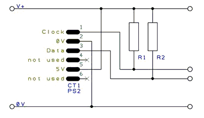
InKey
Syntax:
output = InKey
Command Availability:
Available on all microcontrollers.
Explanation:
The InKey function will read the last pressed key from a PS/2 keyboard,
and return an ASCII value corresponding to the key. If no key is
pressed, then InKey will return 0.
It will also monitor Caps Lock, Num Lock and Scroll Lock keys, and update the status LEDs as appropriate.
Example:
'A program to accept messages from a standard PS/2 keyboard 'Any keys pressed will be shown on an LCD screen. 'Hardware settings #chip 18F4620, 20 'LCD connection settings #define LCD_IO 4 #define LCD_WIDTH 20 ;specified lcd width for clarity only. 20 is the default width #define LCD_DB4 PORTD.4 #define LCD_DB5 PORTD.5 #define LCD_DB6 PORTD.6 #define LCD_DB7 PORTD.7 #define LCD_RS PORTD.0 #define LCD_RW PORTD.1 #define LCD_Enable PORTD.2 'PS/2 connection settings #define PS2Clock PORTC.1 #define PS2Data PORTC.0 #define PS2_DELAY 10 ms 'Set up key log Dim KeyLog(32) DataCount = 0 KeyLog(1) = 32 Main: 'Read the last pressed key KeyIn = INKEY 'If no key pressed, try reading again If KeyIn = 0 Then Goto Main 'Escape pressed - clear message If KeyIn = 27 Then DataCount = 0 For DataPos = 1 to 32 KeyLog(DataPos) = 32 Next Goto DisplayData End If 'Backspace pressed - delete last character If KeyIn = 8 Then If DataCount = 0 Then Goto Main KeyLog(DataCount) = 32 DataCount = DataCount - 1 Goto DisplayData End If 'Otherwise, add the character to the buffer If KeyIn >= 31 And KeyIn <= 127 Then DataCount = DataCount + 1 KeyLog(DataCount) = KeyIn End If DisplayData: 'Display key buffer 'LCDWriteChar is used instead of Print for greater control CLS For DataPos = 1 to DataCount If DataPos = 17 then Locate 1, 0 LCDWriteChar KeyLog(DataPos) Next Goto Main
PS2SetKBLeds
Syntax:
PS2SetKBLeds (LedStatus)
Command Availability:
Available on all microcontrollers.
Explanation:
This routine will turn the status LEDs on a keyboard on or off.
LedStatus is a variable, of which the lower 3 bits correspond to the 3
LEDs. Bit 0 is for Scroll Lock, bit 1 controls Num Lock and bit 2
controls Caps Lock.
Note that this routine does not alter the status variables within the INKEY routine - so even if the Caps Lock LED is turned on, Caps Lock will stay off.
Example:
'A spinning LED program for a keyboard 'Will flash Num Lock, then Caps Lock, then Scroll Lock. 'Hardware settings #chip 16F88, 8 #define PS2Clock PORTB.2 #define PS2Data PORTB.3 #define PS2_DELAY 10 ms 'Main Loop Do 'Turn on only Num Lock (bit 1) PS2SetKBLeds b'00000010' Wait 250 ms 'Turn on only Caps Lock (bit 2) PS2SetKBLeds b'00000100' Wait 250 ms 'Turn on only Scroll Lock (bit 0) PS2SetKBLeds b'00000001' Wait 250 ms Loop
PS2ReadByte
Syntax:
output = PS2ReadByte
Command Availability:
Available on all microcontrollers.
Explanation:
PS2ReadByte will read a byte from the PS/2 bus. It will return the byte,
or 0 if no data was returned by the PS/2 device.
The PS/2 bus will normally be held in the inhibit state. PS2ReadByte
will uninhibit the bus for 25 ms. If a response is received, it will be
read. Then, the bus will be placed back in the inhibit state.
Example:
For an example, please refer to the InKey function.
PS2 Inkey
PS2WriteByte
Syntax:
PS2WriteByte user_data
Command Availability:
Available on all microcontrollers.
Explanation:
PS2WriteByte will send a byte to a PS/2 device. Once the byte has been
written, the PS/2 bus will be placed in the inhibit state.
Example:
For an example, please refer to the PS2SetKBLeds function.
PS2 Set Keyboard Leds
SPI
This is the Serial Peripheral Interface section of the Help file. Please refer the sub-sections for details using the contents/folder view.
SPI Overview
Syntax:
The SPI interface allows for the transmission and receiption of data simultaneously on two lines (MOSI and MISO).
The Clock polarity (CPOL) and clock phase (CPHA) are the main parameters that define a clock format to be used by the SPI bus. Depending on CPOL parameter, SPI clock may be inverted or non-inverted. CPHA parameter is used to shift the sampling phase. If CPHA=0 the data are sampled on the leading (first) clock edge. If CPHA=1 the data are sampled on the trailing (second) clock edge, regardless of whether that clock edge is rising or falling.
CPOL=0, CPHA=0
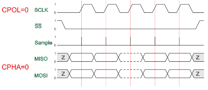
The data must be available before the first clock signal rising. The clock idle state is zero. The data on MISO and MOSI lines must be stable while the clock is high and can be changed when the clock is low. The data is captured on the clock’s low-to-high transition and propagated on high-to-low clock transition.
CPOL=0, CPHA=1
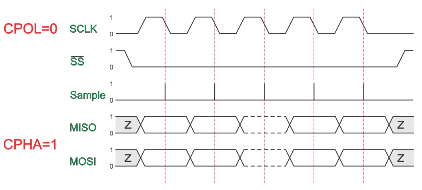
The first clock signal rising can be used to prepare the data. The clock idle state is zero. The data on MISO and MOSI lines must be stable while the clock is low and can be changed when the clock is high. The data is captured on the clock’s high-to-low transition and propagated on low-to-high clock transition.
CPOL=1, CPHA=0
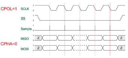
The data must be available before the first clock signal falling. The clock idle state is one. The data on MISO and MOSI lines must be stable while the clock is low and can be changed when the clock is high. The data is captured on the clock’s high-to-low transition and propagated on low-to-high clock transition.
CPOL=1, CPHA=1
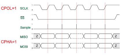
The first clock signal falling can be used to prepare the data. The clock idle state is one. The data on MISO and MOSI lines must be stable while the clock is high and can be changed when the clock is low. The data is captured on the clock’s low-to-high transition and propagated on high-to-low clock transition.
Key Commands
// Set the mode
SPIMode ( _Mode_ [, SPIClockMode]) //Legacy SPI
SPIMode ( _Mode_ , SPIClockMode) //18FxxQxx, 18FxxK42 and 18xxFK83 microcontrollers
// Send bytge and receive data byte
SPITransfer ( _OutByte_, _InByte_ )
// Send data byte
FastHWSPITransfer( _OutByte_ )
// USe MASTERSLOW | MASTER | MASTERFAST | MASTERULTRAFAST for specific AVRs only | MasterSSPADDMode for specific PICs SSPADD support
// The system constant `HWSPIMode` defaults to MASTERFAST when microcontroller frequency less or equal to 32 mhz
// Defaults to MASTER when microcontroller frequency more than 32 mhz.
// To change use the following method
#define HWSPIMode MASTERULTRAFAST
The GCBASIC used the microcontrollers hardware module for SPI. The example below shows an implementation of Hardware and Software SPI. Software SPI allows for a greater choice of ports to be used to control the SPI operations.
To use a second SPI hardware module use the suffix 2, as follows:
// Set the mode
SPIMode2 ( _Mode_ [, SPIClockMode]) //Legacy SPI
SPIMode2 ( _Mode_ , SPIClockMode) //18FxxQxx, 18FxxK42 and 18xxFK83 microcontrollers
// Send bytge and receive data byte
SPITransfer2 ( _OutByte_, _InByte_ )
// Send data byte
FastHWSPITransfer2( _OutByte_ )
Example
This example demonstrates the SPI capabilities for the mega328p. The process is similar of any microcontroller..
This example show using the hardware SPI option and a sofware SPI option.
Using hardware SPI mode - make sure the #define SPI_HardwareSPI is not commented out.
Using software SPI mode - comment out #define SPI_HardwareSPI. The example code will then use software SPI.
Using multiple SPI devices
There will be use cases were you need to use more than one SPI target device at a time. In such cases the device defined for SPI must be inserted in your program for each device.
As an example using e-Paper and SRAM at the same time, with an hardware SPI would require #define SPISRAM_HARDWARESPI and #define EPD_HardwareSPI.
Obviously, when all SPI devices use the same SPI lines, you must select one device at a time by setting SPI Chip Select line to OFF for the specific target SPI device, and you must set ON the SPI Chip Select line for any other SPI device - this is a normal convention of SPI usage. This is not specific to GCBASIC..
Code overview
For more code examples see the demonstrations and the SPIMODE Help page.
In this example InitSPIMode calls SPIMode. If needed, when hardware mode, and set the port directions.
The sub SendByteviaSPI is called to handle whether to call the Hardware or use Software (bit-banging) SPI.
#chip mega328p, 16
#option explicit
#include <UNO_mega328p.h >
#define SPI_HardwareSPI 'comment this out to make into Software SPI but, you may have to change clock lines
'Pin mappings for SPI - this SPI driver supports Hardware SPI
#define SPI_DC DIGITAL_8 ' Data command line
#define SPI_CS DIGITAL_4 ' Chip select line
#define SPI_RESET DIGITAL_9 ' Reset line
#define SPI_DI DIGITAL_12 ' Data in | MISO
#define SPI_DO DIGITAL_11 ' Data out | MOSI
#define SPI_SCK DIGITAL_13 ' Clock Line
dir SPI_DC out
dir SPI_CS out
dir SPI_RESET out
dir SPI_DO Out
dir SPI_DI In
dir SPI_SCK Out
'If DIGITAL_10 is NOT used as the SPI_CS (sometimes called SS) the port must and output or set as input/pulled high with a 10k resistor.
'As follows:
'If CS is configured as an input, it must be held high to ensure Master SPI operation.
'If the CS pin is driven low by peripheral circuitry when the SPI is configured as a Master with the SS pin defined as an input, the
'SPI system interprets this as another master selecting the SPI as a slave and starting to send data to it!
'If CS is an output SPI communications will commence with no flow control.
dir DIGITAL_10 Out
DIM byte1 As byte
DIM byte2 As byte
DIM byte3 As byte
byte1 = 100 ' temp values (will come from potentiometer later)
byte2 = 150
byte3 = 200
InitSPIMode
do forever
set SPI_CS OFF;
set SPI_DC OFF;
SendByteviaSPI (byte1)
set SPI_CS ON;
set SPI_DC ON
set SPI_CS OFF;
set SPI_DC OFF;
SendByteviaSPI (byte2)
set SPI_CS ON;
set SPI_DC ON
set SPI_CS OFF;
set SPI_DC OFF;
SendByteviaSPI (byte3)
set SPI_CS ON;
set SPI_DC ON
wait 10 ms
loop
sub InitSPIMode
#ifdef SPI_HardwareSPI
SPIMode ( MasterFast, SPI_CPOL_0 + SPI_CPHA_0 )
#endif
set SPI_DO OFF;
set SPI_CS ON; therefore CPOL=0
set SPI_DC ON; deselect
End sub
sub SendByteviaSPI( in SPISendByte as byte )
set SPI_CS OFF
set SPI_DC OFF;
#ifdef SPI_HardwareSPI
FastHWSPITransfer SPISendByte
set SPI_CS ON;
exit sub
#endif
#ifndef SPI_HardwareSPI
repeat 8
if SPISendByte.7 = ON then
set SPI_DO ON;
else
set SPI_DO OFF;
end if
SET SPI_SCK On; ; therefore CPOL=0 ==ON, and, where CPOL=1==ON
rotate SPISendByte left
set SPI_SCK Off; ; therefore CPOL=0 =OFF, and, where CPOL=1==OFF
end repeat
set SPI_CS ON;
set SPI_DO OFF;
#endif
end Sub
See also SPIMode,SPITransfer,FastHWSPITransfer
SPIMode
Syntax:
Legacy SPI Operations
SPIMode ( _Mode_ [, _SPIClockMode_])
// Specfic the hardware SPI operating mode, can be MasterFast, Master, MasterSlow
#DEFINE HWSPIMode MasterFast
// You can use a shared constant to set a consant with the desired SPIClockMode
#DEFINE HWSPIClockMode SPI_CPOL_0 + SPI_CPHA_0
AVRDX, 18FxxQxx, 18FxxK42 and 18xxFK83 microcontrollers
For HWSPI channel 0
SPIMode ( _Mode_ , _SPIClockMode_ )
// Specfic the hardware SPI operating mode, can be MasterUltraFast, MasterFast, Master, MasterSlow
#DEFINE HWSPIMode MasterUltraFast
// You can use a shared constant to set a consant with the desired SPIClockMode
#DEFINE HWSPIClockMode SPI_SS_0 + SPI_CPOL_0 + SPI_CPHA_0
// Optionally change the SPI BAUD RATE from 4000
#DEFINE SPI_BAUD_RATE 8000
// Optionally update the SPI baud rate register with an explicit value
// typical use is to entry a specific calculated value
#DEFINE SPI_BAUD_RATE_REGISTER 55
Command Availability:
Available on Microchip PIC and AVR microcontrollers with Hardware SPI modules.
Explanation:
Mode sets the mode of the SPI module within the microcontroller. These are the possible SPI Modes:
| Mode Name | Description |
|---|---|
Legacy SPI Operations |
|
|
Master mode, SPI clock is 1/64 of the frequency of the microcontroller. |
|
Master mode, SPI clock is 1/16 of the frequency of the microcontroller. |
|
Master mode, SPI clock is 1/4 of the frequency of the microcontroller. |
AVRDX, 18FxxQxx, 18FxxK42 and 18xxFK83 microcontrollers |
|
|
SPI clock baud rate is calculated INT( ChipMHz / INT( SPI_BAUD_RATE ) / 16 * 1000) + 1. Where SPI_BAUD_RATE defaults to 4000. Also, see |
|
SPI clock baud rate is calculated as INT( ChipMHz / INT( SPI_BAUD_RATE ) / 4 * 1000) + 1. Where SPI_BAUD_RATE defaults to 4000. Also, see |
|
SPI clock baud rate is calculated as INT( ChipMHz / INT( SPI_BAUD_RATE ) / 2 * 1000) + 1. Where SPI_BAUD_RATE defaults to 4000. Also, see |
|
SPI1BAUD is set to 0 and therefore the SPI clock baud rate to maximum |
Slave Operations |
|
|
Slave mode |
|
Slave mode, with the Slave Select pin enabled. |
For Legacy microcontrollers SPI operations SPIClockMode is an optional parameter to set the mode of the SPI clock mode. This optional parameter sets both the clock polarity and clock edge.
For Specific PICs microcontrollers SPI operations SPIClockMode is a mandated parameter to set the mode of the SPI clock mode and the clock polarity bit. This parameter sets both the clock polarity and clock edge.
There is no verification by the compiler if you do use the _SPIClockMode for the 18FxxQxx, 18FxxK42 and 18xxFK83 microcontrollers - the compiler uses the default value of SPI_SS = 0 & SPI_CPOL = 0 & SPI_CPHA = 0 The use of SPI_SS_n requires the PPS to be set. If PPS is not set then the SPI_SS will use the default value specified in the specfic GCBASIC library.
For the _SPIClockMode_range, see the tables below:
| SPIClockMode | Description |
|---|---|
Legacy SPI operations |
|
0 |
SPI_CPOL = 0 & SPI_CPHA = 0 |
1 |
SPI_CPOL = 0 & SPI_CPHA = 1 |
2 |
SPI_CPOL = 1 & SPI_CPHA = 0 |
3 |
SPI_CPOL = 1 & SPI_CPHA = 1 |
18FxxQxx, 18FxxK42 and 18xxFK83 microcontrollers |
|
0 |
SPI_SS = 0 & SPI_CPOL = 0 & SPI_CPHA = 0 |
2 |
SPI_SS = 0 & SPI_CPOL = 1 & SPI_CPHA = 0 |
5 |
SPI_SS = 1 & SPI_CPOL = 0 & SPI_CPHA = 1 |
7 |
SPI_SS = 1 & SPI_CPOL = 1 & SPI_CPHA = 1 |
You can use a constant value or alternatively you can use constants to set the SPIClockMode as follows:
_Legacy SPI microcontrollers_
SPIMode ( MasterFast, SPI_CPOL_n + SPI_CPHA_n )
_18FxxQxx, 18FxxK42 and 18xxFK83 microcontrollers_
SPIMode ( MasterFast, SPI_SS_n + SPI_CPOL_n + SPI_CPHA_n )
Where the following parameters can be used as a calculation to set the SPIClockMode.
| Mode Name | Description |
|---|---|
Legacy SPI operations and AVRs |
|
SPI_CPOL_0 |
CPOL = 0 |
SPI_CPOL_1 |
CPOL = 1 |
SPI_CPHA_0 |
CPHA = 0 |
SPI_CPHA_1 |
CPHA = 1 |
18FxxQxx, 18FxxK42 and 18xxFK83 microcontrollers |
|
SPI_SS_0 |
SS = 0 Clear polarity bit |
SPI_SS_1 |
SS = 1 Set polarity bit |
Explicitly changing the SPI baud rate on 18FxxQxx, 18FxxK42 and 18xxFK83 microcontrollers
You can explicitly change the SPI baud rate by defining the SPI_BAUD_RATE constant as follows. This will change the default SPI baud from 4000 to the specified numeric value.
#DEFINE SPI_BAUD_RATE 8000
You can explicitly set the SPI baud rate register by defining the SPI_BAUD_RATE_REGISTER constant as follows. This will write the explicit numeric value to the SPI baud register. This overwrites any compiler calculated value.
#DEFINE SPI_BAUD_RATE_REGISTER 55
Legacy SPI Summary:
When using SPI setting the clock frequency is completed using SPIMode, and the master must also configure the clock polarity and phase with respect to the data. Using the two options as CPOL and CPHA.
The timing diagram is shown below. The timing is further described and applies to both the master and the slave device.
When CPOL=0 the base value of the clock is zero, i.e. the active state is 1 and idle state is 0.
-
For CPHA=0, data are captured on the clock’s rising edge (low→high transition) and data is output on a falling edge (high→low clock transition).
-
For CPHA=1, data are captured on the clock’s falling edge and data is output on a rising edge.
When CPOL=1 the base value of the clock is one (inversion of CPOL=0), i.e. the active state is 0 and idle state is 1.
-
For CPHA=0, data are captured on clock’s falling edge and data is output on a rising edge.
-
For CPHA=1, data are captured on clock’s rising edge and data is output on a falling edge.
When CPHA=0 means sampling on the first clock edge and , while CPHA=1 means sampling on the second clock edge, regardless of whether that clock edge is rising or falling. Note that with CPHA=0, the data must be stable for a half cycle before the first clock cycle.
In other words, CPHA=0 means transmitting data on the active to idle state and CPHA=1 means that data is transmitted on the idle to active state edge. Note that if transmission happens on a particular edge, then capturing will happen on the opposite edge(i.e. if transmission happens on falling, then reception happens on rising and vice versa). The MOSI and MISO signals are usually stable (at their reception points) for the half cycle until the next clock transition. SPI master and slave devices may well sample data at different points in that half cycle.
This adds more flexibility to the communication channel between the master and slave.
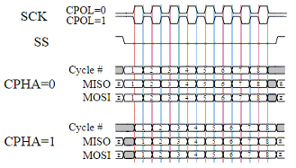
Legacy Example:
This example demonstrates the SPI capabilities for the mega328p. The process is similar of any microcontroller..
You must set the data line as inputs and outputs.
#chip mega328p, 16
#option explicit
#include <UNO_mega328p.h >
#define SPI_HardwareSPI 'comment this out to make into Software SPI but, you may have to change clock lines
'Pin mappings for SPI - this SPI driver supports Hardware SPI
#define SPI_DC DIGITAL_8 ' Data command line
#define SPI_CS DIGITAL_4 ' Chip select line
#define SPI_RESET DIGITAL_9 ' Reset line
#define SPI_DI DIGITAL_12 ' Data in | MISO
#define SPI_DO DIGITAL_11 ' Data out | MOSI
#define SPI_SCK DIGITAL_13 ' Clock Line
dir SPI_DC out
dir SPI_CS out
dir SPI_RESET out
dir SPI_DO Out
dir SPI_DI In
dir SPI_SCK Out
'If DIGITAL_10 is NOT used as the SPI_CS (sometimes called SS) the port must and output or set as input/pulled high with a 10k resistor.
'As follows:
'If CS is configured as an input, it must be held high to ensure Master SPI operation.
'If the CS pin is driven low by peripheral circuitry when the SPI is configured as a Master with the SS pin defined as an input, the
'SPI system interprets this as another master selecting the SPI as a slave and starting to send data to it!
'If CS is an output SPI communications will commence with no flow control.
dir DIGITAL_10 Out
dim outbyte, inbyte as byte
#DEFINE HWSPICLOCKMODE SPI_CPOL_0 + SPI_CPHA_0
SPIMode ( MasterFast, HWSPICLOCKMODE )
do
set SPI_CS OFF// Select line
set SPI_DC OFF// Send Data if off, or, Data if On
SPITransfer ( outbyte, inbyte )
set SPI_CS ON// Deselect Line
set SPI_DC ON
wait 10 ms
loop
18FxxQxx, 18FxxK42 and 18xxFK83 microcontrollers SPI Summary:
When using SPI setting the clock frequency is completed using SPIMode, and the master must also configure the clock polarity and phase with respect to the data. Using the three options as CPOL, CPHA and SS.
The timing diagram is as shown in the prevsious section that impacts CPOL and CPHA.
If you have set the PPS for SPI1SSPPS then control of the SPI SS ( also know as CS / ChipSelect) is automatically controlled by the SPI transmission.
-
Example:*
#CHIP 18F16Q41,64
#STARTUP InitPPS, 85
#DEFINE PPSToolPart 18F16Q41
// Use PPS to assign SPI capabilities to specific ports
SUB InitPPS
SPI1SDIPPS = 0x000C
RB6PPS = 0x001B
SPI1SCKPPS = 0x000E
RB5PPS = 0x001C
RC6PPS = 0x001D
SPI1SSPPS = 0x0016
END SUB
// Optionally change the SPI BAUD RATE from 4000
// #DEFINE SPI_BAUD_RATE 8000
// Optionally update the SPI baud rate register with an explicit value
// typical use is to entry a specific calculated value
// #DEFINE SPI_BAUD_RATE_REGISTER 1
// Specfic the hardware SPI operating model
// Can be MasterUltraFast, MasterFast, Master, MasterSlow
#DEFINE HWSPIMode MasterUltraFast
// You can use a shared constant to set a consant with the desired SPIClockMode
#DEFINE HWSPIClockMode SPI_SS_0 + SPI_CPOL_0 + SPI_CPHA_0
// Call SPIMode
SPIMode (HWSPIMode, HWSPIClockMode )
// Define the GCBASIC required SPI port constants.
// Must match any PPS defined.
#DEFINE SPI_SCK PORTB.6
#DEFINE SPI_DO PORTB.5
#DEFINE SPI_DI PORTB.4
#DEFINE SPI_DC PortC.1
#DEFINE SPI_CS PortC.6
#DEFINE SPI_RESET PortC.2
DO
// Send 0x75 via SPI over and over again...
FastHWSPITransfer 0x75
LOOP
See also SPITransfer,FastHWSPITransfer
SPITransfer
Syntax:
SPITransfer tx, rx
Command Availability:
Available on Microchip PIC microcontrollers with Hardware SPI modules.
Explanation:
This command simultaneously sends and receives a byte of data using the
SPI protocol. It behaves differently depending on whether the microcontroller has
been set to act as a master or a slave.
When operating as a master, SPITransfer will initiate a transfer. The
data in tx will be sent to the slave, whilst the byte that is buffered
in the slave will be read into rx.
In slave mode, the SPITransfer command will pause the program until a
transfer is initiated by the master. At this point, it will send the
data in tx whilst reading the transmission from the master into the
rx variable.
Example:
There are two example programs for this command - one to run on the slave microcontroller , and one on the master. A reading is taken from a sensor on the slave, and sent across to the master which shows the data on its LCD screen.
Slave Program:
'Select chip model and configuration #chip 16F88, 20 #config MCLR_OFF 'Set directions of SPI pins dir PORTB.2 out dir PORTB.1 in dir PORTB.4 in 'Set direction of analogue pin dir PORTA.0 in 'Set SPI mode to slave SPIMode Slave 'Allow other microcontroller to initialise LCD Wait 1 sec 'Main loop - takes a reading, and then waits to send it across. do 'Note that rx is 0 - this is because no data is to be received. SPITransfer ReadAD(AN0), 0 loop
Master Program:
'General hardware configuration
#chip 16F877A, 20
'LCD connection settings
#define LCD_IO 8
#define LCD_WIDTH 20 ;specified lcd width for clarity only. 20 is the default width
#define LCD_DATA_PORT PORTC
#define LCD_RS PORTD.0
#define LCD_RW PORTD.1
#define LCD_Enable PORTD.2
'Set SPI pin directions
dir PORTC.5 out
dir PORTC.4 in
dir PORTC.3 out
'Set SPI Mode to master, with fast clock
SPIMode MasterFast
'Main Loop
do
'Read a byte from the slave
'No data to send, so tx is 0
SPITransfer 0, Temp
'Display data
if Temp > 0 then
CLS
Print "Light: "
LCDInt Temp
Temp = 0
end if
'Wait to allow time for the LCD to show the given value
wait 100 ms
loop
See also SPIMode,FastHWSPITransfer
FastHWSPITransfer
Syntax:
FastHWSPITransfer tx
Command Availability:
Available on Microchip PIC microcontrollers with Hardware SPI modules.
Explanation:
This command only sends a byte of data using the SPI protocol. This command only supports master mode.
As a master, FastHWSPITransfer will initiate a transfer. The
data in tx will be sent to the slave.
Example:
This is an example for this command.
Master Program:
'General hardware configuration
#chip 16F877A, 20
'Set SPI pin directions
dir PORTC.5 out
dir PORTC.4 in
dir PORTC.3 out
'Set SPI Mode to master, with fast clock
SPIMode MasterFast
'Main Loop
do
'Send the value of 0x55
FastHWSPITransfer 0x55
loop
See also SPITransfer,SPIMode
SPI2Mode
Syntax:
Legacy SPI Operations
SPI2Mode ( _Mode_ [, _SPIClockMode_])
// Specfic the hardware SPI operating mode, can be MasterFast, Master, MasterSlow
#DEFINE HWSPI2Mode MasterFast
// You can use a shared constant to set a consant with the desired SPIClockMode
#DEFINE HWSPI2ClockMode SPI_CPOL_0 + SPI_CPHA_0
AVRDX, 18FxxQxx, 18FxxK42 and 18xxFK83 microcontrollers
SPI2Mode ( _Mode_ , _SPIClockMode_ )
// Specfic the hardware SPI operating mode, can be MasterUltraFast, MasterFast, Master, MasterSlow
#DEFINE HWSPI2Mode MasterUltraFast
// You can use a shared constant to set a consant with the desired SPIClockMode
#DEFINE HWSPI2ClockMode SPI_SS_0 + SPI_CPOL_0 + SPI_CPHA_0
// Optionally change the SPI BAUD RATE from 4000
#DEFINE SPI2_BAUD_RATE 8000
// Optionally update the SPI baud rate register with an explicit value
// typical use is to entry a specific calculated value
#DEFINE SPI2_BAUD_RATE_REGISTER 55
Command Availability:
Available on Microchip PIC and AVR microcontrollers with Hardware SPI modules.
Explanation:
Mode sets the mode of the SPI module within the microcontroller. These are the possible SPI Modes:
| Mode Name | Description |
|---|---|
Legacy SPI Operations |
|
|
Master mode, SPI clock is 1/64 of the frequency of the microcontroller. |
|
Master mode, SPI clock is 1/16 of the frequency of the microcontroller. |
|
Master mode, SPI clock is 1/4 of the frequency of the microcontroller. |
AVRDX, 18FxxQxx, 18FxxK42 and 18xxFK83 microcontrollers |
|
|
SPI clock baud rate is calculated INT( ChipMHz / INT( SPI2_BAUD_RATE ) / 16 * 1000) + 1. Where SPI2_BAUD_RATE defaults to 4000. Also, see |
|
SPI clock baud rate is calculated as INT( ChipMHz / INT( SPI2_BAUD_RATE ) / 4 * 1000) + 1. Where SPI2_BAUD_RATE defaults to 4000. Also, see |
|
SPI clock baud rate is calculated as INT( ChipMHz / INT( SPI2_BAUD_RATE ) / 2 * 1000) + 1. Where SPI2_BAUD_RATE defaults to 4000. Also, see |
|
SPI1BAUD is set to 0 and therefore the SPI clock baud rate to maximum |
Slave Operations |
|
|
Slave mode |
|
Slave mode, with the Slave Select pin enabled. |
For Legacy microcontrollers SPI operations SPIClockMode is an optional parameter to set the mode of the SPI clock mode. This optional parameter sets both the clock polarity and clock edge.
For Specific PICs microcontrollers SPI operations SPIClockMode is a mandated parameter to set the mode of the SPI clock mode and the clock polarity bit. This parameter sets both the clock polarity and clock edge.
There is no verification by the compiler if you do use the _SPIClockMode for the 18FxxQxx, 18FxxK42 and 18xxFK83 microcontrollers - the compiler uses the default value of SPI_SS = 0 & SPI_CPOL = 0 & SPI_CPHA = 0 The use of SPI_SS_n requires the PPS to be set. If PPS is not set then the SPI_SS will use the default value specified in the specfic GCBASIC library.
For the _SPIClockMode_range, see the tables below:
| SPIClockMode | Description |
|---|---|
Legacy SPI operations |
|
0 |
SPI_CPOL = 0 & SPI_CPHA = 0 |
1 |
SPI_CPOL = 0 & SPI_CPHA = 1 |
2 |
SPI_CPOL = 1 & SPI_CPHA = 0 |
3 |
SPI_CPOL = 1 & SPI_CPHA = 1 |
18FxxQxx, 18FxxK42 and 18xxFK83 microcontrollers |
|
0 |
SPI_SS = 0 & SPI_CPOL = 0 & SPI_CPHA = 0 |
2 |
SPI_SS = 0 & SPI_CPOL = 1 & SPI_CPHA = 0 |
5 |
SPI_SS = 1 & SPI_CPOL = 0 & SPI_CPHA = 1 |
7 |
SPI_SS = 1 & SPI_CPOL = 1 & SPI_CPHA = 1 |
You can use a constant value or alternatively you can use constants to set the SPIClockMode as follows:
_Legacy SPI microcontrollers_
SPIMode ( MasterFast, SPI_CPOL_n + SPI_CPHA_n )
_18FxxQxx, 18FxxK42 and 18xxFK83 microcontrollers_
SPIMode ( MasterFast, SPI_SS_n + SPI_CPOL_n + SPI_CPHA_n )
Where the following parameters can be used as a calculation to set the SPIClockMode.
| Mode Name | Description |
|---|---|
Legacy SPI operations and AVRs |
|
SPI_CPOL_0 |
CPOL = 0 |
SPI_CPOL_1 |
CPOL = 1 |
SPI_CPHA_0 |
CPHA = 0 |
SPI_CPHA_1 |
CPHA = 1 |
18FxxQxx, 18FxxK42 and 18xxFK83 microcontrollers |
|
SPI_SS_0 |
SS = 0 Clear polarity bit |
SPI_SS_1 |
SS = 1 Set polarity bit |
Explicitly changing the SPI baud rate on 18FxxQxx, 18FxxK42 and 18xxFK83 microcontrollers
You can explicitly change the SPI baud rate by defining the SPI2_BAUD_RATE constant as follows. This will change the default SPI baud from 4000 to the specified numeric value.
#DEFINE SPI2_BAUD_RATE 8000
You can explicitly set the SPI baud rate register by defining the SPI2_BAUD_RATE_REGISTER constant as follows. This will write the explicit numeric value to the SPI baud register. This overwrites any compiler calculated value.
#DEFINE SPI2_BAUD_RATE_REGISTER 55
Legacy SPI Summary:
When using SPI setting the clock frequency is completed using SPIMode, and the master must also configure the clock polarity and phase with respect to the data. Using the two options as CPOL and CPHA.
The timing diagram is shown below. The timing is further described and applies to both the master and the slave device.
When CPOL=0 the base value of the clock is zero, i.e. the active state is 1 and idle state is 0.
-
For CPHA=0, data are captured on the clock’s rising edge (low→high transition) and data is output on a falling edge (high→low clock transition).
-
For CPHA=1, data are captured on the clock’s falling edge and data is output on a rising edge.
When CPOL=1 the base value of the clock is one (inversion of CPOL=0), i.e. the active state is 0 and idle state is 1.
-
For CPHA=0, data are captured on clock’s falling edge and data is output on a rising edge.
-
For CPHA=1, data are captured on clock’s rising edge and data is output on a falling edge.
When CPHA=0 means sampling on the first clock edge and , while CPHA=1 means sampling on the second clock edge, regardless of whether that clock edge is rising or falling. Note that with CPHA=0, the data must be stable for a half cycle before the first clock cycle.
In other words, CPHA=0 means transmitting data on the active to idle state and CPHA=1 means that data is transmitted on the idle to active state edge. Note that if transmission happens on a particular edge, then capturing will happen on the opposite edge(i.e. if transmission happens on falling, then reception happens on rising and vice versa). The MOSI and MISO signals are usually stable (at their reception points) for the half cycle until the next clock transition. SPI master and slave devices may well sample data at different points in that half cycle.
This adds more flexibility to the communication channel between the master and slave.
Legacy Example:
This example demonstrates the SPI capabilities for the mega328p. The process is similar of any microcontroller..
You must set the data line as inputs and outputs.
#chip mega328p, 16
#option explicit
#include <UNO_mega328p.h >
#define SPI2_HardwareSPI 'comment this out to make into Software SPI but, you may have to change clock lines
'Pin mappings for SPI - this SPI driver supports Hardware SPI
#define SPI2_DC DIGITAL_8 ' Data command line
#define SPI2_CS DIGITAL_4 ' Chip select line
#define SPI2_RESET DIGITAL_9 ' Reset line
#define SPI2_DI DIGITAL_12 ' Data in | MISO
#define SPI2_DO DIGITAL_11 ' Data out | MOSI
#define SPI2_SCK DIGITAL_13 ' Clock Line
dir SPI_DC out
dir SPI_CS out
dir SPI_RESET out
dir SPI_DO Out
dir SPI_DI In
dir SPI_SCK Out
'If DIGITAL_10 is NOT used as the SPI2_CS (sometimes called SS) the port must and output or set as input/pulled high with a 10k resistor.
'As follows:
'If CS is configured as an input, it must be held high to ensure Master SPI operation.
'If the CS pin is driven low by peripheral circuitry when the SPI is configured as a Master with the SS pin defined as an input, the
'SPI system interprets this as another master selecting the SPI as a slave and starting to send data to it!
'If CS is an output SPI communications will commence with no flow control.
dir DIGITAL_10 Out
dim outbyte, inbyte as byte
#DEFINE HWSPICLOCKMODE SPI_CPOL_0 + SPI_CPHA_0
SPIMode ( MasterFast, HWSPICLOCKMODE )
do
set SPI_CS OFF// Select line
set SPI_DC OFF// Send Data if off, or, Data if On
SPITransfer ( outbyte, inbyte )
set SPI_CS ON// Deselect Line
set SPI_DC ON
wait 10 ms
loop
18FxxQxx, 18FxxK42 and 18xxFK83 microcontrollers SPI Summary:
When using SPI setting the clock frequency is completed using SPIMode, and the master must also configure the clock polarity and phase with respect to the data. Using the three options as CPOL, CPHA and SS.
The timing diagram is as shown in the prevsious section that impacts CPOL and CPHA.
If you have set the PPS for SPI1SSPPS then control of the SPI SS ( also know as CS / ChipSelect) is automatically controlled by the SPI transmission.
-
Example:*
#CHIP 18F16Q41,64
#STARTUP InitPPS, 85
#DEFINE PPSToolPart 18F16Q41
// Use PPS to assign SPI capabilities to specific ports
SUB InitPPS
SPI1SDIPPS = 0x000C
RB6PPS = 0x001B
SPI1SCKPPS = 0x000E
RB5PPS = 0x001C
RC6PPS = 0x001D
SPI1SSPPS = 0x0016
END SUB
// Optionally change the SPI BAUD RATE from 4000
// #DEFINE SPI2_BAUD_RATE 8000
// Optionally update the SPI baud rate register with an explicit value
// typical use is to entry a specific calculated value
// #DEFINE SPI2_BAUD_RATE_REGISTER 1
// Specfic the hardware SPI operating model
// Can be MasterUltraFast, MasterFast, Master, MasterSlow
#DEFINE HWSPIMode MasterUltraFast
// You can use a shared constant to set a consant with the desired SPIClockMode
#DEFINE HWSPIClockMode SPI_SS_0 + SPI_CPOL_0 + SPI_CPHA_0
// Call SPIMode
SPIMode (HWSPIMode, HWSPIClockMode )
// Define the GCBASIC required SPI port constants.
// Must match any PPS defined.
#DEFINe SPI2_SCK PORTB.6
#DEFINe SPI2_DO PORTB.5
#DEFINe SPI2_DI PORTB.4
#DEFINe SPI2_DC PortC.1
#DEFINe SPI2_CS PortC.6
#DEFINe SPI2_RESET PortC.2
DO
// Send 0x75 via SPI over and over again...
FastHWSPITransfer 0x75
LOOP
See also SPITransfer,FastHWSPITransfer
SPI2Transfer
Syntax:
SPI2Transfer tx, rx
Command Availability:
Available on Microchip PIC microcontrollers with Hardware SPI modules.
Explanation:
This command simultaneously sends and receives a byte of data using the
SPI protocol. It behaves differently depending on whether the microcontroller has
been set to act as a master or a slave.
When operating as a master, SPI2Transfer will initiate a transfer. The
data in tx will be sent to the slave, whilst the byte that is buffered
in the slave will be read into rx.
In slave mode, the SPI2Transfer command will pause the program until a
transfer is initiated by the master. At this point, it will send the
data in tx whilst reading the transmission from the master into the
rx variable.
See also SPIMode,FastHWSPI2Transfer
FastHWSPI2Transfer
Syntax:
FastHWSPI2Transfer tx
Command Availability:
Available on Microchip PIC microcontrollers with Hardware SPI modules.
Explanation:
This command only sends a byte of data using the SPI protocol. This command only supports master mode.
As a master, FastHWSPI2Transfer will initiate a transfer. The
data in tx will be sent to the slave.
See also SPITransfer,SPIMode
I2C Software
This is the I2C Software section of the Help file. Please refer the sub-sections for details using the contents/folder view.
I2C Overview
Introduction:
These software routines allow GCBASIC programs to send and receive I2C messages. They can be configured to act as master or slave, and the speed can also be altered.
No hardware I2C module is required for these routines - all communication is handled in software. However, these routines will not work on 12-bit instruction Microchip PIC microcontrollers (10F, 12F5xx and 16F5xx chips).
Relevant Constants:
These constants control the setup of the software I2C routines:
| Constant | Controls | Default Value |
|---|---|---|
I2C_MODE |
Mode of I2C routines (Master or Slave) |
Master |
I2C_DATA |
Pin on microcontroller connected to I2C data |
N/A |
I2C_CLOCK |
Pin on microcontroller connected to I2C clock |
N/A |
I2C_BIT_DELAY |
Time for a bit (used for acknowledge detection) |
2 us |
I2C_CLOCK_DELAY |
Time for clock pulse to remain high |
1 us |
I2C_END_DELAY |
Time between clock pulses |
1 us |
I2C_USE_TIMEOUT |
Set to true if the I2C routines should stop waiting for the I2c bus - the routine will exit if a timeout occurs. Should be used when you need to prevent system lockups on the I2C bus. Supports both software I2C master and slave mode. Will return the variable |
Not Set |
I2C_DISABLE_INTERRUPTS |
Disable interrupts during I2C routines. Important when an i2C clock is part of your solution |
Not defined. |
Example: This example examines the IC2 devices and displays on a terminal. This code will require adaption but the code shows an approach to discover the IC2 devices.
' I2C Overview - using the ChipIno board, see here for information
#chip 16F886, 8
#config MCLRE_ON
' Define I2C settings
#define I2C_MODE Master
#define I2C_DATA PORTC.4
#define I2C_CLOCK PORTC.3
#define I2C_DISABLE_INTERRUPTS ON
'USART/SERIAL PORT via a MAX232 TO PC Terminal
#define USART_BAUD_RATE 9600
#define USART_TX_BLOCKING
Dir PORTc.6 Out
#define USART_DELAY 0 ms
HSerPrintCRLF 2
HSerPrint "I2C Discover using the ChipIno"
HSerPrintCRLF 2
HSerPrint "Started: "
HSerPrint "Searching I2C address space: v0.85"
HSerPrintCRLF
wait 100 ms
dim DeviceID as byte
for DeviceID = 0 to 255
I2CStart
I2CSend ( deviceID )
I2CSend ( 0 )
I2CSend ( 0 )
i2cstop
if I2CSendState = True then
HSerPrint "__"
HSerPrint "ID: 0x"
HSerPrint hex(deviceID)
HSerPrint " (d"
HSerPrint Str(deviceID)
HSerPrint ")"
HSerPrintCRLF
end if
next
HSerPrint "End of Device Search": HSerPrintCRLF 2
End
Supported in <I2C.H>
I2CAckPollState
Syntax:
<test condition> I2CAckPollState
Command Availability:
Available on all microcontrollers except 12 bit instruction Microchip PIC microcontrollers (10F, 12F5xx, 16F5xx chips)
Explanation:
Should only be used when I2C routines are operating in Master mode, this command will return the last state of the acknowledge response from a specific I2C device on the I2C bus.
I2CACKPOLL sets the state of variable I2CAckPollState. I2CAckPollState
can only read - it cannot be set.
Example:
... ' ACK polling removes the need to for the 24xxxxx device to have a 5ms write time I2CACKPOLL( eeprom_device ) ' You check the exit state, ' Use I2CAckPollState to check the state of a target device ...
Supported in <I2C.H>
I2CAckpoll
Syntax:
I2CAckpoll ( I2C_device_address )
Command Availability:
Available on all microcontrollers except 12 bit instruction Microchip PIC microcontrollers (10F, 12F5xx, 16F5xx chips)
Explanation:
Should only be used when I2C routines are operating in Master mode, this command will look for a specific I2C device on the I2C bus.
This sets a global variable I2CAckPollState that can be inspected in
your calling routine.
Example:
... ' ACK polling removes the need to for the 24xxxxx device to have a 5ms write time I2CACKPOLL( eeprom_device ) ' You check the exit state, use I2CAckPollState to check the state of ' the acknowledge from the target device ...
Supported in <I2C.H>
I2CReceive
Syntax:
I2CReceive data I2CReceive data, ack
Command Availability:
Available on all microcontrollers except 12 bit instruction Microchip PIC microcontrollers (10F, 12F5xx, 16F5xx chips)
Explanation:
The I2CReceive command will send data through the I2C connection. If
ack is TRUE, or no value is given for ack, then I2CReceive will send
an ack.
If in master mode, I2CReceive will read the data immediately.
If in slave mode, I2CReceive will wait for the master to send the data
before reading. When the method I2CReceive is used in Slave mode the
global variable I2CMatch will be set to true when the received value is
equal to the constant I2C_ADDRESS.
Example 1 - Master Mode:
' I2C Receive - using the ChipIno board, see here for information. ' This program reads an I2C register and LED is set to on if the value is over 100.
' This program will read from address 83, register 1.
#chip 16F886, 8
#config MCLRE_ON
'I2C settings
#define I2C_MODE Master
#define I2C_DATA PORTC.4
#define I2C_CLOCK PORTC.3
'Misc settings
#define LED PORTB.5
dir LED Out
'Main loop
Do
'Send start
I2CStart
'Request value
I2CSend 83
I2CSend 1
'Read value
I2CReceive ValueIn
'Send stop
I2CStop
'Turn on LED if received value > 100
Set LED Off
If ValueIn > 100 Then Set LED On
'Delay
Wait 20 ms
Loop
Example 2 - Slave Mode:
See the I2C Overview for the Master mode device to control this Slave mode device.
' I2CReceive_Slave.gcb - using a 16F88.
' This program receives commands from a GCB Master. This Slave has three LEDs attached.
;----- Configuration
#chip 16F88, 8
#config MCLR_OFF
#define I2C_MODE Slave ;this is a slave device now
#define I2C_CLOCK portb.4 ;SCL on pin 10
#define I2C_DATA portb.1 ;SDA on pin 7
#define I2C_ADDRESS 0x60 ;address of the slave device
;----- Variables
dim addr, reg, value as byte
;----- Program
#define LED0 porta.2 ;pin 1
#define LED1 porta.3 ;pin 2
#define LED2 porta.4 ;pin 3
dir LED0 out ;0, 1 and 2 are outputs (LEDs)
dir LED1 out ;0, 1 and 2 are outputs (LEDs)
dir LED2 out ;0, 1 and 2 are outputs (LEDs)
do
I2CStart ;wait for Start signal
I2CReceive( addr ) ;then wait for an address
if I2CMatch = true then ;if it matches, proceed
I2CReceive(regval, ACK) ;get the register number
I2CReceive(value, ACK) ;and its value
I2CStop ;release the bus from this end
select case regval ;now turn proper LED on or off
case 0:
if value then
set LED0 on
else
set LED0 off
end if
case 1:
if value then
set LED1 on
else
set LED1 off
end if
case 2:
if value then
set LED2 on
else
set LED2 off
end if
case else
;other register numbers are ignored
end select
else
I2CStop ;release bus in any event
end if
loop
Supported in <I2C.H>
I2CReset
Syntax:
I2CReset
Command Availability:
Available on all microcontrollers except 12 bit instruction Microchip PIC microcontrollers (10F, 12F5xx, 16F5xx chips)
Explanation:
This will attempt a reset of the I2C by changing the state of the I2C bus.
Example:
... I2CReset ...
Supported in <I2C.H>
I2CRestart
Syntax:
I2CRestart
Command Availability:
Available on all microcontrollers except 12 bit instruction Microchip PIC microcontrollers (10F, 12F5xx, 16F5xx chips)
Explanation:
If the I2C routines are operating in Master mode, this command will send a start and restart condition in a single command.
Example:
... I2CRESTART ....
Supported in <I2C.H>
I2CSend
Syntax:
I2CSend data I2CSend data, ack
Command Availability:
Available on all microcontrollers except 12 bit instruction Microchip PIC microcontrollers (10F, 12F5xx, 16F5xx chips)
Explanation:
The I2CSend command will send data through the I2C connection. If
ack is TRUE, or no value is given for ack, then I2CSend will wait
for an Ack from the receiver before continuing.
If in master mode, I2CSend will send the data immediately. If in slave
mode, I2CSend will wait for the master to request the data before
sending.
Example 1:
' I2CSend - using the ChipIno board, see here for information. ' This program send commands to a GCB Slave with three LEDs attached. #chip 16F886, 8 #config MCLRE_ON 'I2C settings #define I2C_MODE Master #define I2C_DATA PORTC.4 #define I2C_CLOCK PORTC.3 #define I2C_BIT_DELAY 20 us #define I2C_CLOCK_DELAY 30 us #define I2C_ADDRESS 0x60 ;address of the slave device ;----- Variables dim reg as byte ;----- Program do for reg = 0 to 2 ;three LEDs to control I2CStart ;take control of the bus I2CSend I2C_ADDRESS ;address the device if I2CSendState = ACK then I2CSend reg ;address the particular register I2CSend ON ;command to turn on LED end if I2CStop ;relinquish the bus wait 100 ms next reg wait 1 S ;pause to show results for reg = 0 to 2 ;similarly, turn them off I2CStart ;take control of the bus I2CSend I2C_ADDRESS ;address the device if I2CSendState = ACK then I2CSend reg ;address the particular register I2CSend OFF ;command to turn off LED end if I2CStop ;relinquish the bus wait 100 ms next reg wait 1 S ;pause to show results loop
Example 2:
'This program will act as an I2C analog to digital converter 'When data is requested from address 83, registers 0 through '3, it will return the value of AN0 through AN3. 'Chip model #chip 16F88, 8 'I2C settings #define I2C_MODE Slave #define I2C_CLOCK PORTB.0 #define I2C_DATA PORTB.1 #define I2C_DISABLE_INTERRUPTS ON 'Main loop Do 'Wait for start condition I2CStart 'Get address I2CReceive Address If Address = 83 Then 'If address was this device's address, respond I2CReceive Register OutValue = ReadAD(Register) I2CSend OutValue End If I2CStop Wait 5 ms Loop
Specific control of I2CSend
The I2CSend method can be controller with command(s) the change the behaviour of method. The behaviour can be changed as a Prefix or Suffix therefore the start or end of the method.
The two macros ( defined constants) are I2CPreSendMacro and I2CPostSendMacro. The macros must be a single line, with colon delimiters are permitted.
Examples
The following defined macros change the start and end behaviour.
#define I2CPreSendMacro if LabI2CState <> True then exit Sub 'I2CPreSendMacro to ensure GLCD operations only operate within specfic lab #define I2CPostSendMacro if LabI2CState = True then MSSP =1 'I2CPostSendMacro to ensure GLCD operations only operate within specfic lab setting a specific variable.
The following defined macro changes- the start behaviour to call an alternative I2CSend method.
#define I2CPreSendMacro myI2CSend: exit sub
sub myI2CSend
// your i2C handler
end sub
The following defined macros changes- the start behaviour to call an alternative I2CSend method, then jump to the I2CPostSendMacroLabel which is at the end of I2CSend method.
#define I2CPreSendMacro myI2CSend: goto I2CPostSendMacroLabel
#define I2CPostSendMacro NOP
sub myI2CSend
// your i2C handler
end sub
This will generate the following ASM. The I2CPreSendMacro calls the MYI2CSEND() methhod, then BRAnches to the label I2CPOSTSENDMACROLABEL as the end of the method.
;Source: i2c.h (339) I2CSEND ;I2CPreSendMacro rcall MYI2CSEND bra I2CPOSTSENDMACROLABEL ;I2C_CLOCK_LOW 'begin with SCL=0 bcf TRISC,3,ACCESS bcf LATC,3,ACCESS ... lots of ASM ... ;wait I2C_BIT_DELAY 'wait the usual bit length nop nop I2CPOSTSENDMACROLABEL ;I2CPostSendMacro nop return
Supported in <I2C.H>
I2CStart
Syntax:
I2CStart
Command Availability:
Available on all microcontrollers except 12 bit instruction Microchip PIC microcontrollers (10F, 12F5xx, 16F5xx chips)
Explanation:
If the I2C routines are operating in Master mode, this command will send a start condition. If routines are in Slave mode, it will pause the program until a start condition is sent by the master. It should be placed at the start of every I2C transmission.
If interrupt handling is enabled, this command will disable it.
Example:
Please see I2CSend and I2CReceive for an example.
Supported in <I2C.H>
I2CStartoccurred
Syntax:
I2CStartoccurred
Command Availability:
Available on all microcontrollers except 12 bit instruction Microchip PIC microcontrollers (10F, 12F5xx, 16F5xx chips)
Explanation:
If the I2C routine IS operating in Slave mode, this function will check if a start condition has occurred since the last run of this function. 'Only used in slave mode
Example:
Please see I2CSend and I2CReceive for an example.
Supported in <I2C.H>
I2CStop
Syntax:
I2CStop
Command Availability:
Available on all microcontrollers except 12 bit instruction microcontrollers (10F, 12F5xx, 16F5xx chips)
Explanation:
When in Master mode, this command will send an I2C stop condition, and
re-enable interrupts if I2CStart disabled them. In Slave mode, it will
re- enable interrupts.
I2CStop should be called at the end of every I2C transmission.
Example:
Please see I2CSend and I2CReceive for an example.
Supported in <I2C.H>
I2C/TWI Hardware Module
This is the I2C/TWI section of the Help file. Please refer the sub-sections for details using the contents/folder view.
HI2C Overview
Introduction:
These methods allow GCBASIC programs to send and receive Inter- Integrated Circuit (I2C™) messages via:
-
Master Synchronous Serial Port (MSSP) module of the microcontroller for the Microchip PIC architecture, or
-
ATMEL 2-wire Serial Interface (TWI) for the Atmel AVR microcontroller architecture.
These methods are serial interfaces that are useful for communicating with other peripheral or microcontroller devices. These peripheral devices may be serial EEPROMs, shift registers, display drivers, A/D converters, etc.
This method can operate in one of two operational modes:
-
Master Mode, or
-
Slave mode (with general address call)
These methods fully implement all the I2C master and slave functions (including general call support) and supports interrupts on start and stop bits in hardware to determine a free bus (multi-master function).
These methods implement the standard mode specifications as well as 7-bit and 10-bit addressing. A “glitch” filter is built into the SCL and SDA pins when the pin is an input. This filter operates in both the 100 KHz and 400 KHz modes. In the 100 KHz mode, when these pins are an output, there is a slew rate control of the pin that is independent of device frequency.
A hardware I2C/TWI module within the microcontroller is required for these methods.
The driver supports two hardware I2C ports. The second port is addressed by the suffix HI2C2. All HI2C commands are applicable to the second HI2C2 port.
For the Microchip I2C modules Specific for the 18F class including the K42, K83 and Q10, see the later section regarding clock sources and I2C frequencies.
The method supports the following frequencies:
| Frequency | Description | Support |
|---|---|---|
Up to 400 kbits/s |
I2C/TWI |
Supported |
Up to 100 kbit/s. |
I2C/TWI |
Supported |
Up to 1 Mbit/s. |
I2C |
Supported on I2C Module Only Requires alternative clock source to be set. |
Up to 3.4 Mbit/s. |
I2C |
Supported on I2C Module Only Requires alternative clock source to be set. |
Relevant Constants:
These constants control the setup of the hardware I2C methods:
| Constant | Controls | Usage |
|---|---|---|
|
Operational mode of the microcontroller |
|
|
Operational mode of the microcontroller |
|
|
Operational speed of the microcontroller. Defaults to 100 kbit/s |
For Microchip SSP or MSSP modules and AVR microcontrollers:
For Microchip I2C module: 'define HI2C_BAUD_RATE 125' is the default KHz. You can override this value if you set up an alternative clock source. To change use: |
|
Sets the TSCL period to Zero as the Stop condition must be held for TSCL after Stop transition. Default to 70, some solutions can use this set to 0. The clock source and clock method must be reviewed before changing this setting. To change use: #define HI2CITSCLWaitPeriod = 70 |
HI2CITSCLWaitPeriod = 70 |
HIC2Q2XBUFFERSIZE |
The 18FxxQ20 and 18FxxQ24 I2C buffer size. These specific microcontrollers require an I2C buffer to support I2C TX and RX operations. To change use: #define HIC2Q2XBUFFERSIZE = 16 |
HIC2Q2XBUFFERSIZE = 128 |
Port Settings:
The settings of the pin direction is critical to the operation of these
methods.
For the Microchip SSP/MSSP modules both ports must be set as input.
For the Microchip I2C module both ports must be set as output. And, configure the pins as open-drain and set the I2C levels - see example below for usage.
In all case the data and clock line *must * be pulled up with an
appropriate resistor (typically 4.k @ 5.0v for 100Mkz transmissions).
| Constant | Controls | Default Value |
|---|---|---|
|
Pin on microcontroller connected to I2C data |
Must be defined |
|
Pin on microcontroller connected to I2C clock) |
Must be defined |
Microchip I2C modules Specific Support - 18F class including the K42, k47, K83, Q43, Q40/Q41, Q83/Q84, and Q71
Clock Sources: The Microchip I2C can select one of ten clocks sources as shown in the table below. I2C1Clock_MFINTOSC is the default which supports 125KHz.
It is important to change the clock source from the default of 125KHz if you want faster I2C communications. Change the following constant to change the clock source.
Obviously, you setup the clock source correctly for I2C to operate:
#define I2C1CLOCKSOURCE I2C1CLOCK_MFINTOSC
Clock Constants that can be I2C clock sources are
| Constant | Clock Source | Default Value |
|---|---|---|
I2C1CLOCK_SMT1 |
SMT |
0x09+ You MUST setup the SMT clock source. |
I2C1CLOCK_TIMER6PSO |
Timer 6 Postscaler |
0x08+ You MUST setup the timer6 clock source. |
I2C1CLOCK_TIMER4PSO |
Timer 4 Postscaler |
0x07+ You MUST setup the timer4 clock source. |
I2C1CLOCK_TIMER2PSO |
Timer 2 Postscaler |
0x06+ You MUST setup the timer3 clock source. |
I2C1CLOCK_TIMER0OVERFLOW |
Timer 0 Overflow |
0x05+ You MUST setup the timer0 clock source. |
I2C1CLOCK_REFERENCEOUT |
Reference clock out |
0x04+ You MUST ensure the clock source generates a within specification clock source. Check the datasheet for more details. |
I2C1CLOCK_MFINTOSC |
MFINTOSC |
0x03 (default)+ This is the default and will set the I2C clock to 125KHz |
I2C1CLOCK_HFINTOSC |
HFINTOSC |
0x02+ You MUST ensure the clock source generates a within specification clock source. Check the datasheet for more details. |
I2C1CLOCK_FOSC |
FOSC |
0x01+ You MUST ensure the clock source generates a within specification clock source. Check the datasheet for more details. |
I2C1CLOCK_FOSC4 |
FOSC/4 |
0x00+ You MUST ensure the clock source generates a within specification clock source. Check the datasheet for more details. |
This an example of using a Clock Source. This example uses the SMTClock source as the clock source, the following methods implement the SMT as the clock source. The defintion of the constant, the include, setting of the SMT period, initialisation and starting of the clock source are ALL required.
'Set the clock source constant
#define I2C1CLOCKSOURCE I2C1CLOCK_SMT1
'include the SMT capability
#Include <SMT_Timers.h>
'Setup the SMT
'400 KHz @ 64MHZ
Setsmt1Period ( 39 )
' 100 KHz @ 64MHZ
' Setsmt1Period ( 158 )
'Initialise and start the SMT
InitSMT1(SMT_FOSC,SMTPres_1)
StartSMT1
For other clock sources refer to the appropriate datasheet.
Error Codes: This module has extensive error reporting. For the standard error report refer to the appropriate datasheet. GCBASIC also exposes the following error messages to enable the user code to handle the errors appropriately. These are exposed via the variable HI2C1lastError - the bits of the HI2C1lastError are set as in the table shown below.
| Constant | Error Value/Bit |
|---|---|
I2C1_GOOD |
0 |
I2C1_FAIL_TIMEOUT |
1 |
I2C1_TXBE_TIMEOUT |
2 |
I2C1_START_TIMEOUT |
4 |
I2C1_RESTART_TIMEOUT |
8 |
I2C1_RXBF_TIMEOUT |
16 |
I2C1_ACK_TIMEOUT |
32 |
I2C1_MDR_TIMEOUT |
64 |
I2C1_STOP_TIMEOUT |
128 |
Shown below are two examples of using Hardware I2C with GCBASIC.
Example 1:
This example examines the IC2 modules using the Microchip SSP/MSSP module and the AVR microcontrollers. This will display the result on a serial terminal.
This code will require adaption but the code shows an approach to
discover the IC2 devices.
#chip mega328p, 16
#config MCLRE_ON
' Define I2C settings
#define HI2C_BAUD_RATE 400
#define HI2C_DATA PORTC.5
#define HI2C_CLOCK PORTC.4
'I2C pins need to be input for SSP module when used on Microchip PIC device
Dir HI2C_DATA in
Dir HI2C_CLOCK in
'MASTER MODE
HI2CMode Master
'USART/SERIAL PORT WORKS WITH max232 THEN TO PC Terminal
#define USART_BAUD_RATE 9600
#define USART_TX_BLOCKING
Dir PORTc.6 Out
#define USART_DELAY 0 ms
HSerPrintCRLF 2
HSerPrint "Hardware I2C Discover using the "
HSerPrint CHipNameStr
HSerPrintCRLF 2
for deviceID = 0 to 255
HI2CStart
HI2CSend ( deviceID )
if HI2CAckPollState = false then
if (( deviceID & 1 ) = 0 ) then
HSerPrint "W"
else
HSerPrint "R"
end if
HSerSend 9
HSerPrint "ID: 0x"
HSerPrint hex(deviceID)
HSerSend 9
HSerPrint "(d)"+str(deviceID)
HSerPrintCRLF
HI2CSend ( 0 )
end if
HI2CStop
next
HSerPrintCRLF
HSerPrint "End of Device Search"
HSerPrintCRLF 2
This example examines the IC2 devices and displays on a serial terminal for the I2C module only.
This code will require adaption but the code shows an approach to discover the IC2 devices.
This code will only operate on the Microchip I2C module.
#chip 18f25k42, 16
#option Explicit
#config MCLRE_ON
#startup InitPPS, 85
Sub InitPPS
RC4PPS = 0x22 'RC4->I2C1:SDA1
RC3PPS = 0x21 'RC3->I2C1:SCL1
I2C1SCLPPS = 0x13 'RC3->I2C1:SCL1
I2C1SDAPPS = 0x14 'RC4->I2C1:SDA1
'Module: UART1
RC6PPS = 0x0013 'TX1 > RC6
U1RXPPS = 0x0017 'RC7 > RX1
End Sub
'Template comment at the end of the config file
'Setup Serial port
#define USART_BAUD_RATE 9600
#define USART_TX_BLOCKING
' Define I2C settings
#define HI2C_BAUD_RATE 125
#define HI2C_DATA PORTC.4
#define HI2C_CLOCK PORTC.3
'Initialise I2C - note for the I2C module the ports need to be set to Output.
Dir HI2C_DATA out
Dir HI2C_CLOCK out
RC3I2C.TH0=1 'Port specific controls may be required - see the datasheet
RC4I2C.TH0=1 'Port specific controls may be required - see the datasheet
'For this solution we can set the TSCL period to Zero as the Stop condition must be held for TSCL after Stop transition
#define HI2CITSCLWaitPeriod 0
'*****************************************************************************************************
'Main program commences here.. everything before this is setup for the board.
dim DeviceID as byte
Dim DISPLAYNEWLINE as Byte
do
HSerPrintCRLF
HSerPrint "Hardware I2C "
HSerPrintCRLF 2
' Now assumes Serial Terminal is operational
HSerPrintCRLF
HSerPrint " "
'Create a horizontal row of numbers
for DeviceID = 0 to 15
HSerPrint hex(deviceID)
HSerPrint " "
next
'Create a vertical column of numbers
for DeviceID = 0 to 255
DisplayNewLine = DeviceID % 16
if DisplayNewLine = 0 Then
HSerPrintCRLF
HserPrint hex(DeviceID)
if DisplayNewLine > 0 then
HSerPrint " "
end if
end if
HSerPrint " "
'Do an initial Start
HI2CStart
if HI2CWaitMSSPTimeout <> True then
'Send to address to device
HI2CSend ( deviceID )
'Did device fail to respond?
if HI2CAckPollState = false then
HI2CSend ( 0 )
HSerPrint hex(deviceID)
Else
HSerPrint "--"
end if
'Do a stop.
HI2CStop
Else
HSerPrint "! "
end if
next
HSerPrintCRLF 2
HSerPrint "End of Search"
HSerPrintCRLF 2
wait 1 s
wait while SwitchIn = On
loop
Supported in <HI2C.H>
HI2CAckPollState
Syntax:
<test condition[s]> HI2CAckPollState
Command Availability:
Only available for microcontrollers with the hardware I2C or TWI module.
Explanation:
Should only be used when I2C routines are operating in Master mode, this command will return the last state of the acknowledge response from a specific I2C device on the I2C bus.
HI2CSend sets the state of variable HI2CAckPollState.
HI2CAckPollState can only read - it cannot be set.
Note:
This command is also available on microcontrollers with a second hardware I2C port.
<test condition[s]> HI2C2AckPollState
Example:
This example code would display the devices on the I2C bus.
...
for deviceID = 0 to 255
HI2CStart
HI2CSend ( deviceID )
if HI2CAckPollState = false then
HSerPrint "ID: 0x"
HSerPrint hex(deviceID)
HSerSend 9
end if
next
...
Supported in <HI2C.H>
HI2CReceive
Syntax:
HI2CReceive data
HI2CReceive data, ACK
HI2CReceive data, NACK
Command Availability:
Only available for microcontrollers with the hardware I2C or TWI module.
Explanation:
The HI2CReceive command will send data through the I2C connection. If
ack is TRUE, or no value is given for ack, then HI2CReceive will send
an ack to the I2C bus.
If in master mode, HI2CReceive will read the data immediately. If in
slave mode, HI2CReceive will wait for the master to send the data before
reading.
Note:
This command is also available on microcontrollers with a second hardware I2C port.
HI2C2Receive _data_
HI2C2Receive _data_, ACK
HI2C2Receive _data_, NACK
Example 1:
'This program reads an I2C register and sets an LED if it is over 100.
'It will read from I2C device with an address of 83, register 1.
' Change the processor
#chip 16F1937, 32
#config MCLRE_ON
' Define I2C settings
#define HI2C_BAUD_RATE 400
#define HI2C_DATA PORTC.4
#define HI2C_CLOCK PORTC.3
'I2C pins need to be input for SSP module
Dir HI2C_DATA in
Dir HI2C_CLOCK in
'MASTER I2C Device
HI2CMode Master
'Misc settings
#define LED PORTB.0
'Main loop
Do
'Send start
HI2CStart
'Request value
HI2CSend 83
HI2CSend 1
'Read value
HI2CReceive ValueIn
'Send stop
HI2CStop
'Turn on LED if received value > 100
Set LED Off
If ValueIn > 100 Then Set LED On
'Delay
Wait 20 ms
Loop
Example 2:
See the I2C Overview for the Master mode device to control this Slave mode device.
' I2CHardwareReceive_Slave.gcb - using a 16F88.
' This program receives commands from a GCB Master. This Slave has three LEDs attached.
; This Slave device responds to address 0x60 and may only be written to.
; Within it, there are three registers, 0,1 and 2 corresponding to the three LEDs. Writing a zero
; turns the respective LED off. Writing anything else turns it on.
#chip 16F88, 4
#config MCLR_Off
#define I2C_MODE Slave ;this is a slave device now
#define I2C_CLOCK portb.4 ;SCL on pin 10
#define I2C_DATA portb.1 ;SDA on pin 7
#define I2C_ADDRESS 0x60 ;address of the slave device
#define I2C_BIT_DELAY 20 us
#define I2C_CLOCK_DELAY 10 us
#define I2C_END_DELAY 10 us
'Serial settings
#define SerInPort PORTB.6
#define SerOutPort PORTB.7
#define SendAHigh Set SerOutPort OFF
#define SendALow Set SerOutPort On
'Set pin directions
Dir SerOutPort Out
Dir SerInPort In
'Set up serial connection
InitSer 1, r2400, 1 + WaitForStart, 8, 1, none, INVERT
wait 1 s
#define LED0 porta.2 ;pin 1
#define LED1 porta.3 ;pin 2
#define LED2 porta.4 ;pin 3
;----- Variables
dim addr, reg, value,location as byte
addr = 255
reg = 255
value = 255
location = 0
mempointer = 255
;----- Program
dir LED0 out ;0, 1 and 2 are outputs (LEDs)
dir LED1 out ;0, 1 and 2 are outputs (LEDs)
dir LED2 out ;0, 1 and 2 are outputs (LEDs)
set LED0 off
set LED1 off
set LED2 off
#define SerialControlPort portb.3
dir SerialControlPort in
'Set up interrupt to process I2C
dir I2C_CLOCK in ; required to input for MSSP module
dir I2C_DATA in ; required to input for MSSP module
SSPADD=I2C_ADDRESS ; Slave address
SSPSTAT=b'00000000' ; configuration
SSPCON=b'00110110' ; configuration
PIE1.SSPIE=1 ; enable interrupt
repeat 3 ;flash LEDs
set LED0 on
set LED1 on
set LED2 on
wait 50 ms
set LED0 off
set LED1 off
set LED2 off
wait 100 ms
end Repeat
oldvalue = 255 ; old value, set up value only
oldreg = 255 ; old value, set up value only
UpdateLEDS ; call method to set LEDs
; set up interrupt
On Interrupt SSP1Ready call I2C_Interrupt
do forever
if reg <> oldreg then ; only process when the reg is a new value
oldreg = reg ; retain old value
show = 1 ; its time to show the LEDS!
if value <> oldvalue then ; logic for tracking old values. You only want to update terminal once per change
oldvalue = value
show = 1
end if
end if
UpdateLEDS ; Update date LEDs
; update serial terminal
if show = 1 and SerialControlPort = 1 then
SerPrint 1, "0x"+hex(addr)
SerSend 1,9
SerPrint 1, STR(reg)
SerSend 1,9
SerPrint 1, STR(value)
SerSend 1,10
SerSend 1,13
show = 0
end if
loop
Sub I2C_Interrupt
' handle interrupt
IF SSPIF=1 THEN ; its a valid interrupt
IF SSPSTAT.D_A=0 THEN ; its an address coming in!
addr=SSPBUF
IF addr=I2C_ADDRESS THEN ; its our address
mempointer = 0 ; set the memory pointer. This code emulates an EEPROM!
end if
IF addr = ( I2C_ADDRESS | 1 ) THEN ; its our write address
CKP = 0 ; acknowledge command
; If the SDA line was low (ACK), the transmit data must be loaded into
; the SSPBUF register which also loads the SSPSR
; register. Then, pin RB4/SCK/SCL should be enabled
; by setting bit CKP.
mempointer = 10 ; set a pointer to track incoming write reqests
if I2C_DATA = 0 then
SSPBUF = 0x22
CKP = 1
readpointer = 0x55
end if
end if
else
if SSPSTAT.P = 1 then ' Stop bit has been detected - out of sequence
' handle event
end if
IF SSPSTAT.S = 1 THEN ' Start bit has been detected - out of sequence
' handle event
END IF
IF SSPSTAT.R_W = 0 THEN ' Write operations requested
SELECT CASE mempointer
CASE 0
reg = SSPBUF ' incoming value
mempointer++ ' increment our counter
CASE 1
value = SSPBUF ' incoming value
mempointer++ ' increment our counter
CASE ELSE
dummy = SSPBUF ' incoming value
END SELECT
ELSE ' Read operations
SSPBUF = readpointer ' incoming value
readpointer++ ' increment our counter
END IF
END IF
CKP = 1 ' acknowledge command
SSPOV = 0 ' acknowledge command
END IF
SSPIF=0
END SUB
sub UpdateLEDS
select case reg ;now turn proper LED on or off
case 0
if value = 1 then
set LED0 on
else
set LED0 off
end if
case 1
if value = 1 then
set LED1 on
else
set LED1 off
end if
case 2
if value = 1 then
set LED2 on
else
set LED2 off
end if
end select
End Sub
Supported in <HI2C.H>
HI2CRestart
Syntax:
HI2CRestart
Command Availability:
Only available for microcontrollers with the hardware I2C or TWI module.
Explanation:
If the HI2C routines are operating in Master mode, this command will send a start and restart condition in a single command.
Note:
This command is also available on microcontrollers with a second hardware I2C port.
HI2C2Restart
Example:
do
HI2CReStart ;generate a start signal
HI2CSend(eepDev) ;inidcate a write
loop While HI2CAckPollState
HI2CSend(eepAddr_H) ;as two bytes
HI2CSend(eepAddr)
HI2CReStart
HI2CSend(eepDev + 1) ;indicate a read
eep_i = 0 ;loop consecutively
do while (eep_i < eepLen) ;these many bytes
eep_j = eep_i + 1 ;arrays begin at 1 not 0
if (eep_i < (eepLen - 1)) then
HI2CReceive(eepArray(eep_j), ACK) ;more data to get
else
HI2CReceive(eepArray(eep_j), NACK ) ;send NACK on last byte
end if
eep_i++ ;get set for next
loop
HI2CStop
Supported in <HI2C.H>
==== HI2CSend
Syntax:
HI2CSend data
Command Availability:
Only available for microcontrollers with the hardware I2C or TWI module.
Explanation:
The HI2CSend command will send data through the I2C connection.
If in master mode, HI2CSend will send the data immediately. If in slave
mode, HI2CSend will wait for the master to request the data before
sending.
Note:
This command is also available on microcontrollers with a second hardware I2C port.
HI2C2Send data
Example:
This example code retrieves multiple bytes from an EEPROM memory device.
do HI2CReStart ;generate a start signal HI2CSend(eepDev) ;indicate a write loop While HI2CAckPollState HI2CSend(eepAddr_H) ;as two bytes HI2CSend(eepAddr) HI2CReStart HI2CSend(eepDev + 1) ;indicate a read eep_i = 0 ;loop consecutively do while (eep_i < eepLen) ;these many bytes eep_j = eep_i + 1 ;arrays begin at 1 not 0 if (eep_i < (eepLen - 1)) then HI2CReceive(eepArray(eep_j), ACK) ;more data to get else HI2CReceive(eepArray(eep_j), NACK ) ;send NACK on last byte end if eep_i++ ;get set for next loop HI2CStop
Supported in <HI2C.H>
HI2CStart
Syntax:
HI2CStart
Command Availability:
Only available for microcontrollers with the hardware I2C or TWI module.
Explanation:
If the HI2C routines are operating in Master mode, this command will send a start condition. If routines are in Slave mode, it will pause the program until a start condition is sent by the master. It should be placed at the start of every I2C transmission.
Note:
This command is also available on microcontrollers with a second hardware I2C port.
HI2C2Start
Example:
Please see HI2CSend and HI2CReceive for examples.
Supported in <HI2C.H>
HI2CStartOccurred
Syntax:
HI2CStartOccurred
Command Availability:
Only available for microcontrollers with the hardware I2C or TWI module.
Explanation:
Check if a start condition has occurred since the last run of this function
Only used in slave mode.
Note:
This command is also available on microcontrollers with a second hardware I2C port.
HI2C2StartOccurred
Supported in <HI2C.H>
HI2CMode
Syntax:
HI2CMode Master | Slave
Command Availability:
Only available for microcontrollers with the hardware I2C or TWI module.
Explanation:
Sets the microcontroller to either a Master device or a Slave device.
Only used in slave mode
Note:
This command is also available on microcontrollers with a second hardware I2C port.
HI2C2Mode Master | Slave
Supported in <HI2C.H>
HI2CSetAddress
Syntax:
HI2CSetAddress address_number
Command Availability:
Only available for microcontrollers with the hardware I2C or TWI module.
Explanation:
Sets the microcontroller address number in Slave mode.
Only used in slave mode.
Note:
This command is also available on microcontrollers with a second hardware I2C port.
HI2C2SetAddress address_number
Supported in <HI2C.H>
HI2CStop
Syntax:
HI2CStop
Command Availability:
Only available for microcontrollers with the hardware I2C or TWI module.
Explanation:
HI2CStop should be called at the end of every I2C transmission.
Note:
This command is also available on microcontrollers with a second hardware I2C port.
HI2C2Stop
Example:
Please see HI2CSend and HI2CReceive for an example.
Supported in <HI2C.H>
HI2CStopped
Syntax:
HI2CStopped
Command Availability:
Only available for microcontrollers with the hardware I2C or TWI module.
Explanation:
In Slave mode only. Check if start condition received since last used of HI2CStopped.
Note:
This command is also available on microcontrollers with a second hardware I2C port.
HI2C2Stopped
Supported in <HI2C.H>
HI2CWaitMSSP
Syntax:
HI2CWaitMSSP
Command Availability:
Only available for microcontrollers with the hardware I2C or TWI module.
Explanation:
The methods sets the global byte variable HI2CWaitMSSPTimeout to 255 ( or True ) if the MSSP module has timeout during operations.
HI2CWaitMSSPTimeout can tested for the status of the I2C bus.
Note:
This command is also available on microcontrollers with a second hardware I2C port.
HI2C2WaitMSSP
Supported in <HI2C.H>
Sound
This is the Sound section of the Help file. Please refer the sub-sections for details using the contents/folder view.
Sound Overview
Introduction:
These GCBASIC methods generate tones of a given frequency and duration.
| Method | Controls |
|---|---|
Tone |
Generate a specified tone for a specified duration in terms of a frequency of a specified Mhz and units of 10ms |
ShortTone |
Generate a specified tone for a specified duration in terms of a frequency of a 10Mhz and units of 1ms |
Play |
Play a tune string. The format of the string is the QBASIC play command. |
PlayRTTTL |
Play a tune string. The format of the string is the Nokia cell phone RTTTL format. |
Relevant Constants:
These constants are used to control settings for the tone generation routines. To set them, place a line in the main program file that uses #define to assign a value to the particular constant.
| Constant Name | Controls | Default Value |
|---|---|---|
|
The output pin to produce sound on |
N/A - Must be defined |
Note: If an exact frequency is required, or a smaller program is needed, these routines should not be used. Instead, you should use code like this:
Repeat count
PulseOut SoundOut, period us
Wait period us
End Repeat
Set count and period to the appropriate values as follows:
period to 1000000 / desired frequency / 2
count to desired duration / period.
Tone
Syntax:
Tone Frequency, Duration
Command Availability:
Available on all microcontrollers.
Explanation:
This command will produce the specified tone for the specified duration.
Frequency is measured in Hz, and Duration is in 10 ms units.
Please note that this command may not produce the exact frequency specified. While it is accurate enough for error beeps and small pieces of monophonic music, it should not be used for anything that requires a highly precise frequency.
Example:
'Sample program to produce a constant A note (440 Hz)
'on PORTB bit 1.
#chip 16F877A, 20
#define SoundOut PORTB.1
Do
Tone 440, 1000
Loop
For more help, see Sound Overview
ShortTone
Syntax:
ShortTone Frequency, Duration
Command Availability:
Available on all microcontrollers.
Explanation:
This command will produce the specified tone for the specified duration. Frequency is measured in units of 10 Hz, and Duration is in 1 ms units. Please note that this command may not produce the exact frequency specified. While it is accurate enough for error beeps and small pieces of monophonic music, it should not be used for anything that requires a highly precise frequency.
Example:
'Sample program to produce a tone on PORTB bit 1, based on the
'reading of an LDR on AN0 (usually PORTA bit 0).
#chip 16F88, 20
#define SoundOut PORTB.1
Dir PORTA.0 In
Do
ShortTone ReadAD(AN0), 100
Loop
For more help, see Sound Overview
Play
Syntax:
Play SoundPlayDataString
You must specify the following include and the port of the sound device.
#include <songplay.h>
#define SOUNDOUT PORTN.N
Command Availability:: Available on all microcontrollers.
Explanation: This command will plays a QBASIC sequence of notes. The SoundPlayDataString is a string representing a musical note or notes to play where Notes are A to G.
| Command | Description |
|---|---|
A - G |
May be followed by length: 2 = half note, 4 = quarter, also may be followed by # or + (sharp) or - (flat). |
On |
Sets current octave. n is octave from 0 to 6 |
Pn |
Pause playing. n is length of rest |
Ln: |
Set default note length. n = 1 to 8. |
< or > |
Change down or up an octave |
Tn: |
Sets tempo in L4s/minute. n = 32 to 255, default 120. |
Nn |
Play note n. n = 0 to 84, 0 = rest. |
Unsupported QBASIC commands are
| Command | Description |
|---|---|
M |
Play mode |
. |
Changes note length |
For more information on the QBASIC PLAY command set, see https://en.wikibooks.org/wiki/QBasic/Appendix
Example:
'Sample program to play a string
'on PORTB bit 1.
#chip 16F877A, 20
#include <songplay.h>
#define SoundOut PORTB.1
play "C C# C C#"
For more help, see Sound Overview
Play RTTTL
Syntax:
PlayRTTTL SoundPlayRTTTLDataString
You must specify the following include and the port of the sound device.
#include <songplay.h>
#define SOUNDOUT PORTN.N
Command Availability:: Available on all microcontrollers.
Explanation: This command will play a sequence of notes in the Nokia RTTTL string format.
The SoundPlayRTTTLDataString is a string representing a musical note or notes to play where Notes are A to G. This format and information below is credited to WikiPedia, see here. To be recognized by ringtone programs, an RTTTL/Nokring format ringtone must contain three specific elements: name, settings, and notes. For example, here is the RTTTL ringtone for Haunted House:
HauntHouse: d=4,o=5,b=108: 2a4, 2e, 2d#, 2b4, 2a4, 2c, 2d, 2a#4, 2e., e, 1f4, 1a4, 1d#, 2e., d, 2c., b4, 1a4, 1p, 2a4, 2e, 2d#, 2b4, 2a4, 2c, 2d, 2a#4, 2e., e, 1f4, 1a4, 1d#, 2e., d, 2c., b4, 1a4
The three parts are separated by a colon.
-
Part 1: name of the ringtone (here: "HauntHouse"), a string of characters represents the name of the ringtone
-
Part 2: settings (here: d=4,o=5,b=108), where "d=" is the default duration of a note. In this case, the "4" means that each note with no duration specifier (see below) is by default considered a quarter note. "8" would mean an eighth note, and so on. Accordingly, "o=" is the default octave. There are four octaves in the Nokring/RTTTL format. And "b=" is the tempo, in "beats per minute".
-
Part 3: the notes. Each note is separated by a comma and includes, in sequence: a duration specifier, a standard music note, either a, b, c, d, e, f or g, and an octave specifier. If no duration or octave specifier are present, the default applies.
Example 1:
#chip 16f877a
#include <songplay.h>
#define SOUNDOUT PORTA.4
PlayRTTTL "HauntHouse: d=4,o=5,b=108: 2a4, 2e, 2d#, 2b4, 2a4, 2c, 2d, 2a#4, 2e., e, 1f4, 1a4, 1d#, 2e., d, 2c., b4, 1a4, 1p, 2a4, 2e, 2d#, 2b4, 2a4, 2c, 2d, 2a#4, 2e., e, 1f4, 1a4, 1d#, 2e., d, 2c., b4, 1a4"
Example 2:
#chip 16f877a
#include <songplay.h>
'Defines
#define SoundOut PORTC.0
Dir SoundOut Out
Dim SoundPlayRTTTLDataString as String
wait 1 s
SoundPlayRTTTLDataString = "Thegood,:d=4,o=6,b=63:32c,32f,32c,32f,c,8g_5,8a_5,f5,8p,32c,32f,32c,32f,c,8g_5,8a_5,d_"
PlayRTTTL(SoundPlayRTTTLDataString)
wait 1 s
SoundPlayRTTTLDataString ="LedZeppel:d=4,o=6,b=80:8g,16p,8f_,16p,8f,16p,8e,16p,8d,8a5,8c,16p,8b5,16p,a_5,8a5,16f5,16e5,16d5,8p,16p,16a_5,16a_5,16a_5,8p,16p,16b5,16b5,16b5,8p,16p,16b5,16b5,16b5,8p,16p,16c,16c,16c,8p,16p,16c,16c,16c"
PlayRTTTL(SoundPlayRTTTLDataString)
Do Forever
Loop
End
For more help, see Sound Overview
Timers
This is the Timers section of the Help file. Please refer the sub-sections for details using the contents/folder view.
Timer Overview
GCBASIC supports methods to set, clear, read, start and stop the microcontroller timers.
GCBASIC supports the following timers.
Timer 0
Timer 1
Timer 2
Timer 3
Timer 4
Timer 5
Timer 6
Timer 7
Timer 8
Timer 10
Timer 12
Not all of these timers available on all microcontrollers. For example,
if a microcontroller has three timers, then typically only Timer0,
Timer1 and Timer2 will be available.
Please refer to the datasheet for your microcontroller to determine the supported timers and if a specific timer is 8-bit or 16-bit.
Calculating a Timer Prescaler:
To initialise and change the timers you may have to change the Prescaler.
A Prescaler is an electronic counting circuit used to reduce a high frequency electrical signal to a lower frequency by integer division. The prescaler takes the basic timer clock frequency and divides it by some value before being processed by the timer, according to how the Prescaler register(s) are configured. The prescaler values that may be configured might be limited to a few fixed values, see the timer specfic page in this Help file or refer to the datasheet.
To use a Prescaler some simple integer maths is required, however, when calculating the Prescaler there is often be a tradeoff between resolution, where a high resolution requires a high clock frequency and range where a high clock frequency willl cause the timer to overflow more quickly. For example, achieving 1 us resolution and a 1 sec maximum period using a 16-bit timer may require some clever thinking when using 8-bit timers. Please ask for advice via the GCBASIC forum, or, search for some of the many great resources on the internet to calculate a Prescaler value.
Common Langauge:
Using timers has the following terms /common langauge. This following paragraph is intended to explain the common language.
The Oscillator (OSC) is the system clock, this can be sourced from an internal or external source, OSC is same the as microcontroller Mhz. This is called the the Frequency of the OSCillator (FOSC) or the System Clock.
On a Microchip PIC microcontroller, one machine code instruction is executed for every four system clock pulses.
This means that instructions are executed at a frequency of FOSC/4.
The Microchip PIC datasheets call this FOSC/4 or FOSC4.
All Microchip PIC timer prescales are based on the FOSC/4, not the FOSC or the System Clock.
As Prescale are based upon FOSC/4, you must use FOSC/4 in your timer calculations to get the results you expect.
All Prescale and Postscale values are integer numbers.
On Atmel AVR microcontroller, most machine code instructions will execute in a single clock pulse.
Timer differences between Microchip PIC and Atmel AVR microcontrollers:
Initialising a timer for a Microchip PIC microcontroller may not operate as expected when using the same code for an Atmel AVR microcontroller by simply changing the #chip definition.
You must recalculate the Prescaler of a timer when moving timer parameters between Microchip PIC and Atmel AVR microcontrollers.
And, of course, the same when moving timer parameters between Atmel AVR and Microchip PIC microcontrollers.
Timer Best Practices:
Initialising microcontrollers with very limited RAM using GCBASIC needs carefull consideration. RAM may be need to be optimised by using ASM to control the timers. You can use GCBASIC to create the timer related GCBASIC ASM code then manually edit the GCBASIC ASM to optmise RAM usage. Add your revised and optimised ASM back into your program and then remove the no longer required calls the the GCBASIC methods. If you need advice on this subject please ask for advice via the GCBASIC forum.
Using Timers 2/4/6/8 on Microchip PIC microcontrollers.
A Microchip PIC microcontroller can have one of two types of 8-bit timer 2/4/6/8.
The first type has only one clock source and that clock is the FOSC/4 source.
The second type is much more flexible and can have many different clock sources and supports more prescale values.
The timer type for a Microchip PIC microcontroller can be determined by checking for the existence of a T2CLKCON register, either in the Datasheet or in the GCBASIC "dat file" for the specific microcontroller.
If the microcontroller DOES NOT have a T2CLKCON register then ALL Timer 2/4/6/8 timers on that chip are the first type, and are configured using:
_InitTimer2 (PreScale, PostScale)_ 'Timer2 is example for timer 2/4/6 or 8
If the microcontroller DOES have a T2CLKCON register then ALL Timer 2/4/6/8 timers on that chip are the second type and are configured using:
_InitTimer2 (Source, PreScale, PostScale)_ 'Timer2 is example for timer 2/4/6 or 8
The possible Source, PreScale and PostScale constants for each type are shown in the GCBASIC Help file. See each timer for the constants.
The "Period" of these timers is determined by the system clock speed, the prescale value and 8-bit value in the respective timer period register. The timer period registers are PR2, PR4, PR6 or PR8 for timer2, timer4, timer6 and timer8 respectively. These registers are also called PRx and TMRx where the x refers to specific timer number.
When a specific timer is enabled/started the TMRx timer register will increment until the TMRx register matches the value in the PRx register. At this time the TMRx register is cleared to 0 and the timer continues to increment until the next match of the PRx register, and so on until the timer is stopped. The lower the value of the PRx register, the shorter the timer period will be. The default value for the PRX register at power up is 255.
The timer interrupt flag (TMRxIF) is set based upon the number of match conditions as determine by the postscaler. The postscaler does not actually change the timer period, it changes the time between interrupt conditions.
ClearTimer
Syntax:
ClearTimer TimerNo
Command Availability:
Available on all Microchip PIC and Atmel AVR microcontrollers with built in timer modules.
Explanation:
ClearTimer is used to clear the specified timer to a value of 0.
Cleartimer can be used on-the-fly if desired, so there is no requirement to
stop the timer first.
Example:
.....
'Clear timer 1
ClearTimer 1
.....
See also, InitTimer1 article for an example.
InitTimer0
Syntax:
InitTimer0 source, prescaler
Command Availability:
Available on all microcontrollers with a Timer 0 module.
See also see: InitTimer0 8bit/16bit for support for microcontrollers with a 8 bit/16 bit Timer 0 module.
Explanation:
InitTimer0 will set up timer 0.
Parameters are required as detailed in the table below:
| Parameter | Description |
|---|---|
|
The clock source for this specific timer. Can be either
|
|
The value of the prescaler for this specific timer. See the tables below for permitted values for Microchip PIC or the Atmel AVR microcontrollers. |
When the timer overflows from 255 to 0, a Timer0Overflow interrupt will
be generated. This can be used in conjunction with On Interrupt to run a
section of code when the overflow occurs.
Microchip PIC microcontrollers:
On Microchip PIC microcontrollers where the prescaler rate select bits are in the range of 2 to 256 you should use one of the following constants. If the prescaler rate select bits are in the range of 1 to 32768 then see the subsequent table.
| Prescaler Value | Primary GCB Constant | Constant Equates to value |
|---|---|---|
1:2 |
|
0 |
1:4 |
|
1 |
1:8 |
|
2 |
1:16 |
|
3 |
1:32 |
|
4 |
1:64 |
|
5 |
1:128 |
|
6 |
1:256 |
|
7 |
These correspond to a prescaler of between 1:2 and 1:256 of the oscillator
speed where the oscillator speed is (FOSC/4). The prescaler applies to
both the internal oscillator or the external clock.
Atmel AVR microcontrollers:
On Atmel AVR microcontrollers prescaler must be one of the following constants:
The prescaler will only apply when the timer is driven from the Osc the
internal oscillator - the prescaler has no effect when the external clock
source is specified.
| Prescaler Value | Primary GCB Constant | Secondary GCB Constant | Constant Equates to value |
|---|---|---|---|
1:1 |
|
|
1 |
1:8 |
|
|
2 |
1:64 |
|
|
3 |
1:256 |
|
|
4 |
1:1024 |
|
|
5 |
Example 1 for 8-bit timer 0:
This code uses Timer 0 and On Interrupt to generate a Pulse Width Modulation signal, that will allow the speed of a motor to be easily controlled.
#chip 16F88, 8
#define MOTOR PORTB.0
'Call the initialisation routine
InitMotorControl
'Main routine
Do
'Increase speed to full over 2.5 seconds
For Speed = 0 to 100
MotorSpeed = Speed
Wait 25 ms
Next
'Hold speed
Wait 1 s
'Decrease speed to zero over 2.5 seconds
For Speed = 100 to 0
MotorSpeed = Speed
Wait 25 ms
Next
'Hold speed
Wait 1 s
Loop
'Setup routine
Sub InitMotorControl
'Clear variables
MotorSpeed = 0
PWMCounter = 0
'Add a handler for the interrupt
On Interrupt Timer0Overflow Call PWMHandler
'Set up the timer using the internal oscillator with a prescaler of 1/2 (Equates to 0)
'Timer 0 starts automatically on a Microchip PIC microcontroller, therefore, StartTimer is not required.
InitTimer0 Osc, PS0_2
End Sub
'PWM sub
'This will be called when Timer 0 overflows
Sub PWMHandler
If MotorSpeed > PWMCounter Then
Set MOTOR On
Else
Set MOTOR Off
End If
PWMCounter += 1
If PWMCounter = 100 Then PWMCounter = 0
End Sub
Example 1 for 18-bit timer 0 operating an 8-bit timer:
The same example for a 16-bit timer 0 operating as an 8-bit timer.
#chip 16f18855,32
#option Explicit
'timer test Program
dim speed, MotorSpeed, PWMCounter as byte
#define MOTOR PORTb.0
dir MOTOR out
'Call the initialisation routine
InitMotorControl
'Main routine
Do
'Increase speed to full over 2.5 seconds
For Speed = 0 to 100
MotorSpeed = Speed
Wait 25 ms
Next
'Hold speed
Wait 1 s
'Decrease speed to zero over 2.5 seconds
For Speed = 100 to 0
MotorSpeed = Speed
Wait 25 ms
Next
'Hold speed
Wait 1 s
Loop
'Setup routine
Sub InitMotorControl
'Clear variables
MotorSpeed = 0
PWMCounter = 0
'Add a handler for the interrupt
On Interrupt Timer0Overflow Call PWMHandler
InitTimer0(Osc, TMR0_FOSC4 + PRE0_1 , POST0_1)
StartTimer 0
End Sub
'PWM sub
'This will be called when Timer 0 overflows
Sub PWMHandler
If MotorSpeed > PWMCounter Then
Set MOTOR On
Else
Set MOTOR Off
End If
PWMCounter += 1
If PWMCounter = 100 Then PWMCounter = 0
End Sub
Supported in <TIMER.H>
InitTimer0 8bit/16bit
Syntax:
InitTimer0 source, prescaler + clocksource, postscaler
Timer are useful as timers can generate interrupts.
Timers can be used in conjunction with On Interrupt to run a section of code when a specific timer event occurs.
Example events are when the timer matches a specific value, or, the timer resets to a zero value.
For more details on timer events see On Interrupt.
Command Availability:
Available on microcontrollers with a Timer 0 where the timer has the capability of operating as an 8 bit or 16 bit timer. This type of Timer 0 can be found on Microchip PIC 18(L)F, as well as small number of 18C and 16(L)F microcontrollers. These timers can be configured for either 8-bit or 16-bit operation.
You may need to refer to the datasheet for your microcontroller to determine if it supports both 8-bit and 16-bit operations.
Explanation for 8-bit timer:
The default operation is as an 8-bit timer.
InitTimer0 will set up timer 0.
Parameters are required as shown in the table below:
| Parameter | Description |
|---|---|
|
The clock source for this specific timer. Can be either
|
|
The value of the prescaler for this specific timer, and, the clocksource See the tables below for permitted values for Microchip PIC or the Atmel AVR microcontrollers. |
|
The value of the postscaler for this specific timer. See the tables below for permitted values for Microchip PIC or the Atmel AVR microcontrollers. |
8 bit Example:
The example show in the osc as an internal source, a prescaler value of 256 witht the HFINTOSC clocksource and a postscaler value of 2
InitTimer0 Osc, PRE0_256 + TMR0_HFINTOSC , POST0_2
'also, note when in 8-bit mode you MUST set the 8bit timer value to the upper byte of a WORD, when setting the `SetTimer`
SetTimer 0, 0x5800 'Setting the HIGH byte!!!
16 bit Example:
To use the 16 bit timer you need to add the constant #define TMR0_16bit.
The example show in the osc as an internal source, a prescaler value of 256 witht the HFINTOSC clocksource and a postscaler value of 2
#define TMR0_16bit
InitTimer0 Osc, PRE0_256 + TMR0_HFINTOSC , POST0_2
Differences in Timer0 Operations
The section refers to chips with a 8/16-bit Timer0.
When these chips are operating in 8-bit mode, Timer0 behaves much like Timers2/4/6. In 8-bit mode the TMR0H register does not increment. It instead becomes the Period or Match register and is aliased as "PR0" (Period Register 0).
In 8-bit mode, Timer0 does not technically overflow. Instead when TMR0L increments and matches the value in the PR0 register, TMR0L is reset to 0. The interrupt flag bit (TMR0IF) bit is then set (based upon Postscaler).
The default value in the PR0 "match register" is 255. This value can be set/changed in the user program to set/change the timer period. This can be used to fine tune the timer period.
Timer 0 mandated constants:
| Parameter | Description |
|---|---|
|
The clock source for this specific timer. Can be either |
|
The value of the prescaler for this specific timer. See the tables below for permitted values for Microchip PIC or the Atmel AVR microcontrollers.
You may also be required to specify one of the following clock sources. You should use a simple addition to concatenate the prescaler with a specific clock source. For example.
|
|
See the tables below for permitted values for Microchip. |
Microchip PIC microcontrollers where the prescaler rate select bits are in the range of 1 to 32768 you should use one of the following constants.
| Prescaler Value | Primary GCB Constant | Constant Equates to value |
|---|---|---|
1:1 |
|
0 |
1:2 |
|
1 |
1:4 |
|
2 |
1:8 |
|
3 |
1:16 |
|
4 |
1:32 |
|
5 |
1:64 |
|
6 |
1:128 |
|
7 |
1:256 |
|
8 |
1:512 |
|
9 |
1:1024 |
|
10 |
1:2048 |
|
11 |
1:4096 |
|
12 |
1:8192 |
|
13 |
1:16384 |
|
14 |
1:32768 |
|
15 |
These correspond to a prescaler of between 1:1 and 1:32768 of the oscillator speed where the oscillator speed is (FOSC/4). The prescaler applies to both the internal oscillator or the external clock.
On Microchip PIC microcontrollers where the prescaler rate select bits are in the range of 2 to 256 you should use one of the following constants. If the prescaler rate select bits are in the range of 1 to 32768 then see the subsequent table.
| Prescaler Value | Primary GCB Constant | Constant Equates to value |
|---|---|---|
1:2 |
|
0 |
1:4 |
|
1 |
1:8 |
|
2 |
1:16 |
|
3 |
1:32 |
|
4 |
1:64 |
|
5 |
1:128 |
|
6 |
1:256 |
|
7 |
These correspond to a prescaler of between 1:2 and 1:256 of the oscillator
speed where the oscillator speed is (FOSC/4). The prescaler applies to
both the internal oscillator or the external clock.
On Microchip PIC microcontroller that require postscaler is can be one of the following constants where the Postscaler Rate Select bits are in the range of 1 to 16.
| Postcaler Value | Primary GCB Constant | Use Numeric Constant |
|---|---|---|
1:1 |
|
0 |
1:2 |
|
1 |
1:3 |
|
2 |
1:4 |
|
3 |
1:5 |
|
4 |
1:6 |
|
5 |
1:7 |
|
6 |
1:8 |
|
7 |
1:9 |
|
8 |
1:10 |
|
9 |
1:11 |
|
10 |
1:12 |
|
11 |
1:13 |
|
12 |
1:14 |
|
13 |
1:15 |
|
14 |
1:16 |
|
15 |
Example:
This code uses Timer 0 and On Interrupt to flash an LED.
/*
Remember four things to setup a timer.
1. InitTimer0 source, prescaler + clocksource, postscaler
2. SetTimer (byte_value, value ), or
SetTimer (word_value [where the High byte sets the timer], value )
3. StartTimer 0
and, optionally use
4. ClearTimer 0
*/
'Chip Settings.
#CHIP 16f18313, 32
Dir porta.1 Out
'Setup the timer.
' Source, Prescaler + Clock Source , Postscaler
InitTimer0 Osc, PRE0_16384 + TMR0_HFINTOSC , POST0_11
' Set the Timer start value. Use the HIGH byte of the word when using an 8/16bit timer in 8 bit mode
SetTimer ( 0, 0x5800 )
' Start the Timer by writing to TMR0ON bit
StartTimer 0
Do
Wait While TMR0IF = 0
' Clearing timer flag
TMR0IF = 0
porta.1 = ! porta.1
Loop
Supported in <TIMER.H>
See also see: InitTimer0 for microcontroller with only an 8 bit Timer 0 module.
InitTimer1
Syntax:
InitTimer1 source, prescaler
Command Availability:
Available on all microcontrollers with a Timer 1 module.
Explanation:
InitTimer1 will set up timer 1.
Parameters are required as detailed in the table below:
| Parameter | Description |
|---|---|
|
The clock source for this specific timer. Can be either
Enhanced Microchip PIC microcontrollers with a dedicated TMRxCLK register support additional clock sources. This includes, but limited to, the following devices: 16F153xx, 16F16xx, 16F188xx and 18FxxK40 Microchip PIC microcontroller series. On these devices the clock source can be one of the following:
|
|
The value of the prescaler for this specific timer. See the tables below for permitted vales for Microchip PIC or the Atmel AVR microcontrollers. |
When the timer overflows an interrupt event will be generated.
This interrupt event can be used in conjunction with On Interrupt to run a section of code when the interrupt event occurs.
Microchip PIC microcontrollers:
On Microchip PIC microcontrollers prescaler must be one of the following constants:
| Prescaler Value | Primary GCB Constant | Constant Equates to value |
|---|---|---|
1:1 |
|
0 |
1:2 |
|
16 |
1:4 |
|
32 |
1:8 |
|
48 |
These correspond to a prescaler of between 1:2 and 1:8 of the oscillator (FOSC/4)
speed. The prescaler will apply to either the oscillator or the external
clock input.
Atmel AVR microcontrollers:
On the majority of Atmel AVR microcontrollers prescaler must be one of the following constants:
The prescaler will only apply when the timer is driven from the Osc the internal oscillator - the prescaler has no effect when the external clock source is specified.
| Prescaler Value | Primary GCB Constant | Secondary GCB Constant | Constant Equates to value |
|---|---|---|---|
1:0 |
|
|
0 |
1:1 |
|
|
1 |
1:8 |
|
|
2 |
1:64 |
|
|
3 |
1:256 |
|
|
4 |
1:1024 |
|
|
5 |
On Atmel AVR ATtiny15/25/45/85/216/461/861 microcontrollers prescaler must be one of the following constants:
The prescaler will only apply when the timer is driven from the Osc the internal oscillator - the prescaler has no effect when the external clock source is specified.
| Prescaler Value | Primary GCB Constant | Constant Equates to value |
|---|---|---|
1:0 |
|
0 |
1:1 |
|
1 |
1:2 |
|
2 |
1:4 |
|
3 |
1:8 |
|
4 |
1:16 |
|
5 |
1:32 |
|
6 |
1:64 |
|
7 |
1:128 |
|
8 |
1:256 |
|
9 |
1:512 |
|
10 |
1:1024 |
|
11 |
1:2048 |
|
12 |
1:4096 |
|
13 |
1:8192 |
|
14 |
1:16384 |
|
15 |
Example 1 (Microchip):
This example will measure that time that a switch is depressed (or on) and will write the results to the EEPROM.
#chip 16F819, 20
#define Switch PORTA.0
Dir Switch In
DataCount = 0
'Initilise Timer 1
InitTimer1 Osc, PS1_8
Dim TimerValue As Word
Do
ClearTimer 1
Wait Until Switch = On
StartTimer 1
Wait Until Switch = Off
StopTimer 1
'Read the timer
TimerValue = Timer1
'Log the timer value
EPWrite(DataCount, TimerValue_H)
EPWrite(DataCount + 1, TimerValue)
DataCount += 2
Loop
Example 2 (Atmel AVR):
This example will flash the yellow LED on an Arduino Uno (R3) once every second.
#Chip mega328p, 16 'Using Arduino Uno R3
#define LED PORTB.5 Dir LED OUT
Inittimer1 OSC, PS_256 Starttimer 1 Settimer 1, 3200 ;Preload Timer
On Interrupt Timer1Overflow Call Flash_LED
Do
'Wait for interrupt
loop
Sub Flash_LED Settimer 1, 3200 'Preload timer pulseout LED, 100 ms End Sub
Supported in <TIMER.H>
InitTimer2
Syntax: (MicroChip PIC)
InitTimer2 prescaler, postscaler
or, where you required to state the clock source, use the following
InitTimer2 clocksource, prescaler, postscaler
Syntax: (Atmel AVR)
InitTimer2 source, prescaler
Command Availability:
Available on all microcontrollers with a Timer 2 module. As shown above a Microchip microcontroller can potentially support two types of methods for initialisation.
The first method is:
InitTimer2 prescaler, postscaler
This the most common method to initialise a Microchip microcontroller timer. With this method the timer has only one possible clock source, this mandated by the microcontrollers architecture, and that clock source is the System Clock/4 also known as FOSC/4.
The second method is much more flexible in term of the clock source. Microcontrollers that support this second method enable you to select different clock sources and to select more prescale values. The method is shown below:
InitTimer2 clocksource, prescaler, postscaler
How do you determine which method to use for your specific Microchip microcontroller ?
The timer type for a Microchip microcontroller can be determined by checking for the existance of a T2CLKCON register, either in the Datasheet or in the GCBASIC "dat file" for the specific device.
If the Microchip microcontroller DOES NOT have a T2CLKCON register then timers 2/4/6/8 for that specific microcontroller chip use the first method, and are configured using:
InitTimer2 (PreScale, PostScale)
If the microcontroller DOES have a T2CLKCON register then ALL timers 2/4/6/8 for that specific microcontroller chip use the second method, and are configured using:
InitTimer2 (Source,PreScale,PostScale)
The possible Source, Prescale and Postscale constants for each type are shown in the tables below. These table are summary tables from the Microchip datasheets.
Period of the Timers
The Period of the timer is determined by the system clock speed, the prescale value and 8-bit value in the respective timer period register. The timer period for timer 2 is held in register PR2.
When the timer is enabled, by starting the timer, it will increment until the TMR2 register matches the value in the PR2 register. At this time the TMR2 register is cleared to 0 and the timer continues to increment until the next match, and so on.
The lower the value of the PR2 register, the shorter the timer period will be. The default value for the PR2 register at power up is 255.
The timer interrupt flag (TMR2IF) is set based upon the number of match conditions as determine by the postscaler. The postscaler does not actually change the timer period, it changes the time between interrupt conditions.
Timer constants for the MicroChip microcontrollers
Parameters for this timer are detailed in the tables below:
| Parameter | Description |
|---|---|
|
This is an optional parameter. Please review the datasheet for specific usage. Other sources may be available but can vary from microcontroller to microcontroller and these can be included manually per the specific microcontrollers datasheet. |
|
The value of the prescaler for this specific timer. See the tables below for permitted values. |
|
The value of the postscaler for this specific timer. See the tables below for permitted values. |
Table 1 shown above
prescaler can be one of the following settings, if you MicroChip microcontroller has the T2CKPS4 bit then refer to table 3:
| Prescaler Value | Primary GCB Constant | Constant Equates to value |
|---|---|---|
1:1 |
|
0 |
1:4 |
|
1 |
1:16 |
|
2 |
1:64 |
|
3 |
Table 2 shown above
Note that a 1:64 prescale is only avaialable on certain midrange microcontrollers.
Please refer to the datasheet to determine if a 1:64 prescale is supported by a
spectific microcontroller.
| Prescaler Value | Primary GCB Constant | Constant Equates to value |
|---|---|---|
1:1 |
|
0 |
1:2 |
|
1 |
1:4 |
|
2 |
1:8 |
|
3 |
1:16 |
|
4 |
1:32 |
|
5 |
1:64 |
|
6 |
1:128 |
|
7 |
Table 3 shown above
postscaler slows the rate of the interrupt generation (or WDT reset) from a
counter/timer by dividing it down.
On Microchip PIC microcontroller one of the following constants where the Postscaler Rate Select bits are in the range of 1 to 16.
| Postcaler Value | GCB Constant | Eqautes to |
|---|---|---|
1:1 Postscaler |
POST_1 |
0 |
1:2 Postscaler |
POST_2 |
1 |
1:3 Postscaler |
POST_3 |
2 |
1:4 Postscaler |
POST_4 |
3 |
1:5 Postscaler |
POST_5 |
4 |
1:6 Postscaler |
POST_6 |
5 |
1:7 Postscaler |
POST_7 |
6 |
1:8 Postscaler |
POST_8 |
7 |
1:9 Postscaler |
POST_9 |
8 |
1:10 Postscaler |
POST_10 |
9 |
1:11 Postscaler |
POST_11 |
10 |
1:12 Postscaler |
POST_12 |
11 |
1:13 Postscaler |
POST_13 |
12 |
1:14 Postscaler |
POST_14 |
13 |
1:15 Postscaler |
POST_15 |
14 |
1:16 Postscaler |
POST_16 |
15 |
Table 4 shown above
Explanation:(Atmel AVR)
InitTimer2 will set up timer 2, according to the settings given.
source can be one of the following settings:
Parameters for this timer are detailed in the table below:
| Parameter | Description |
|---|---|
|
The clock source for this specific timer. Can be either |
Table 5 shown above
prescaler for Atmel AVR Timer 2 is chip specific and can be selected from one of the two
tables shown below. Please refer to the datasheet determine which table to use and which
prescales within that table are supported by a specific Atmel AVR microcontroller.
Table1: Prescaler Rate Select bits are in the range of 1 to 1024
| Prescaler Value | Primary GCB Constant | Secondary GCB Constant | Constant Equates to value |
|---|---|---|---|
1:0 |
|
|
1 |
1:1 |
|
|
1 |
1:8 |
|
|
2 |
1:64 |
|
|
3 |
1:256 |
|
|
4 |
1:1024 |
|
|
5 |
Table 6 shown above
Prescaler Rate Select bits are in the range of 1 to 16384
| Prescaler Value | Primary GCB Constant | Secondary GCB Constant | Constant Equates to value |
|---|---|---|---|
1:1 |
|
|
1 |
1:2 |
|
|
2 |
1:4 |
|
|
3 |
1:8 |
|
|
4 |
1:16 |
|
|
5 |
1:32 |
|
|
6 |
1:64 |
|
|
7 |
1:128 |
|
|
8 |
1:256 |
|
|
9 |
1:512 |
|
|
10 |
1:1024 |
|
|
11 |
1:2048 |
|
|
12 |
1:4096 |
|
|
13 |
1:8192 |
|
|
14 |
1:16384 |
|
|
15 |
Table 7 shown above
Example:
This code uses Timer 2 and On Interrupt to flash an LED every 200 timer ticks.
#chip 16F1788, 8
#DEFINE LED PORTA.1
DIR LED OUT
#Define Match_Val PR2 'PR2 is the timer 2 match register
Match_Val = 200 'Interrupt afer 200 timer ticks
On interrupt timer2Match call FlashLED 'Interrupt on match
Inittimer2 PS2_64, 15 'Prescale 1:64 /Postscale 1:16 (15)
Starttimer 2
Do
' Wating for interrupt on match val of 100
Loop
'This sub will be called when Timer 2 matches "Match_Val" (PR2)
SUB FlashLED
pulseout LED, 5 ms
END SUB
InitTimer3
Syntax:
InitTimer3 source, prescaler
Command Availability:
Available on all microcontrollers with a Timer 3 module.
Explanation:
InitTimer3 will set up timer 3.
Parameters are required as detailed in the table below:
| Parameter | Description |
|---|---|
|
The clock source for this specific timer. Can be either
Enhanced Microchip PIC microcontrollers with a dedicated TMRxCLK register support additional clock sources. This includes, but limited to, the following devices: 16F153xx, 16F16xx, 16F188xx and 18FxxK40 Microchip PIC microcontroller series On these devices the clock source can be one of the following:
|
|
The value of the prescaler for this specific timer. See the tables below for permitted vales for Microchip PIC or the Atmel AVR microcontrollers. |
When the timer overflows an interrupt event will be generated.
This interrupt event can be used in conjunction with On Interrupt to run a section of code when the interrupt event occurs.
Microchip PIC microcontrollers:
On Microchip PIC microcontrollers prescaler must be one of the following constants:
| Prescaler Value | Primary GCB Constant | Constant Equates to value |
|---|---|---|
1:1 |
|
0 |
1:2 |
|
16 |
1:4 |
|
32 |
1:8 |
|
48 |
These correspond to a prescaler of between 1:2 and 1:8 of the oscillator (FOSC/4)
speed. The prescaler will apply to either the oscillator or the external
clock input.
Atmel AVR microcontrollers:
On the majority of Atmel AVR microcontrollers prescaler must be one of the following constants:
The prescaler will only apply when the timer is driven from the Osc the internal oscillator - the prescaler has no effect when the external clock source is specified.
| Prescaler Value | Primary GCB Constant | Secondary GCB Constant | Constant Equates to value |
|---|---|---|---|
1:0 |
|
|
1 |
1:1 |
|
|
1 |
1:8 |
|
|
2 |
1:64 |
|
|
3 |
1:256 |
|
|
4 |
1:1024 |
|
|
5 |
Supported in <TIMER.H>
InitTimer4
Syntax: (MicroChip PIC)
InitTimer4 prescaler, postscaler
or, where you required to state the clock source, use the following
InitTimer4 clocksource, prescaler, postscaler
Syntax: (Atmel AVR)
InitTimer4 source, prescaler
Command Availability:
Available on all microcontrollers with a Timer 4 module. As shown above a Microchip microcontroller can potentially support two types of methods for initialisation.
The first method is:
InitTimer4 prescaler, postscaler
This the most common method to initialise a Microchip microcontroller timer. With this method the timer has only one possible clock source, this mandated by the microcontrollers architecture, and that clock source is the System Clock/4 also known as FOSC/4.
The second method is much more flexible in term of the clock source. Microcontrollers that support this second method enable you to select different clock sources and to select more prescale values. The method is shown below:
InitTimer4 clocksource, prescaler, postscaler
How do you determine which method to use for your specific Microchip microcontroller ?
The timer type for a Microchip microcontroller can be determined by checking for the existance of a T2CLKCON register, either in the Datasheet or in the GCBASIC "dat file" for the specific device.
If the Microchip microcontroller DOES NOT have a T4CLKCON register then timers 2/4/6/8 for that specific microcontroller chip use the first method, and are configured using:
InitTimer4 (PreScale, PostScale)
If the microcontroller DOES have a T2CLKCON register then ALL timers 2/4/6/8 for that specific microcontroller chip use the second method, and are configured using:
InitTimer4 (Source,PreScale,PostScale)
The possible Source, Prescale and Postscale constants for each type are shown in the tables below. These table are summary tables from the Microchip datasheets.
Period of the Timers
The Period of the timer is determined by the system clock speed, the prescale value and 8-bit value in the respective timer period register. The timer period for timer 4 is held in register PR4.
When the timer is enabled, by starting the timer, it will increment until the TMR4 register matches the value in the PR4 register. At this time the TMR4 register is cleared to 0 and the timer continues to increment until the next match, and so on.
The lower the value of the PR4 register, the shorter the timer period will be. The default value for the PR4 register at power up is 255.
The timer interrupt flag (TMR4IF) is set based upon the number of match conditions as determine by the postscaler. The postscaler does not actually change the timer period, it changes the time between interrupt conditions.
Timer constants for the MicroChip microcontrollers
Parameters for this timer are detailed in the tables below:
| Parameter | Description |
|---|---|
|
If required by method select.
Other sources may be available but can vary from microcontroller to microcontroller and these can be included manually per the specific microcontrollers datasheet. |
|
The value of the prescaler for this specific timer. See the tables below for permitted values. |
|
The value of the postscaler for this specific timer. See the tables below for permitted values. |
Table 1 shown above
prescaler can be one of the following settings, if you MicroChip microcontroller has the T4CKPS4 bit then refer to table 2:
| Prescaler Value | Primary GCB Constant | Constant Equates to value |
|---|---|---|
1:1 |
|
0 |
1:4 |
|
1 |
1:16 |
|
2 |
1:64 |
|
3 |
Table 2
Note that a 1:64 prescale is only avaialable on certain midrange microcontrollers.
Please refer to the datasheet to determine if a 1:64 prescale is supported by a
spectific microcontroller.
| Prescaler Value | Primary GCB Constant | Constant Equates to value |
|---|---|---|
1:1 |
|
0 |
1:2 |
|
1 |
1:4 |
|
2 |
1:8 |
|
3 |
1:16 |
|
4 |
1:32 |
|
5 |
1:64 |
|
6 |
1:128 |
|
7 |
Table 3
postscaler slows the rate of the interrupt generation (or WDT reset) from a
counter/timer by dividing it down.
On Microchip PIC microcontroller one of the following constants where the Postscaler Rate Select bits are in the range of 1 to 16.
| Postcaler Value | Use Numeric Constant |
|---|---|
1:1 Postscaler |
0 |
1:2 Postscaler |
1 |
1:3 Postscaler |
2 |
1:4 Postscaler |
3 |
1:5 Postscaler |
4 |
1:6 Postscaler |
5 |
1:7 Postscaler |
6 |
1:8 Postscaler |
7 |
1:9 Postscaler |
8 |
1:10 Postscaler |
9 |
1:11 Postscaler |
10 |
1:12 Postscaler |
11 |
1:13 Postscaler |
12 |
1:14 Postscaler |
13 |
1:15 Postscaler |
14 |
1:16 Postscaler |
15 |
Explanation:(Atmel AVR)
InitTimer4 will set up timer 4, according to the settings given.
source can be one of the following settings:
Parameters for this timer are detailed in the table below:
| Parameter | Description |
|---|---|
|
The clock source for this specific timer. Can be either |
prescaler for Atmel AVR Timer 4 can be selected from the table below.
Prescaler Rate Select bits are in the range of 1 to 1024
| Prescaler Value | Primary GCB Constant | Secondary GCB Constant | Constant Equates to value |
|---|---|---|---|
1:0 |
|
|
1 |
1:1 |
|
|
1 |
1:8 |
|
|
2 |
1:64 |
|
|
3 |
1:256 |
|
|
4 |
1:1024 |
|
|
5 |
Example:
This code uses Timer 4 and On Interrupt to generate a 1ms pulse 20 ms.
#chip 18F25K80, 8
#DEFINE PIN3 PORTA.1
DIR PIN3 OUT
#Define Match_Val PR4 'PR4 is the timer 2 match register
Match_Val = 154 'Interrupt afer 154 Timer ticks (~20ms)
On interrupt timer4Match call PulsePin3 'Interrupt on match
Inittimer4 PS4_16, 15 'Prescale 1:64 /Postscale 1:16 (15)
Starttimer 4
Do
'Waiting for interrupt on match val of 154
Loop
Sub PulsePin3
pulseout Pin3, 1 ms
End Sub
InitTimer5
Syntax:
InitTimer5 source, prescaler
Command Availability:
Available on all microcontrollers with a Timer 5 module.
Explanation:
InitTimer5 will set up timer 5.
Parameters are required as detailed in the table below:
| Parameter | Description |
|---|---|
|
The clock source for this specific timer. Can be either
Enhanced Microchip PIC microcontrollers with a dedicated TMRxCLK register support additional clock sources. This includes, but limited to, the following devices: 16F153xx, 16F16xx, 16F188xx and 18FxxK40 Microchip PIC microcontroller series On these devices the clock source can be one of the following:
|
|
The value of the prescaler for this specific timer. See the tables below for permitted vales for Microchip PIC or the Atmel AVR microcontrollers. |
When the timer overflows an interrupt event will be generated.
This interrupt event can be used in conjunction with On Interrupt to run a section of code when the interrupt event occurs.
Microchip PIC microcontrollers:
On Microchip PIC microcontrollers prescaler must be one of the following constants:
| Prescaler Value | Primary GCB Constant | Constant Equates to value |
|---|---|---|
1:1 |
|
0 |
1:2 |
|
16 |
1:4 |
|
32 |
1:8 |
|
48 |
These correspond to a prescaler of between 1:2 and 1:8 of the oscillator (FOSC/4)
speed. The prescaler will apply to either the oscillator or the external
clock input.
Atmel AVR microcontrollers:
On the majority of Atmel AVR microcontrollers prescaler must be one of the following constants:
The prescaler will only apply when the timer is driven from the Osc the internal oscillator - the prescaler has no effect when the external clock source is specified.
| Prescaler Value | Primary GCB Constant | Secondary GCB Constant | Constant Equates to value |
|---|---|---|---|
1:0 |
|
|
0 |
1:1 |
|
|
1 |
1:8 |
|
|
2 |
1:64 |
|
|
3 |
1:256 |
|
|
4 |
1:1024 |
|
|
5 |
Supported in <TIMER.H>
InitTimer6
Syntax: (MicroChip PIC)
InitTimer6 prescaler, postscaler
or, where you required to state the clock source, use the following
InitTimer6 clocksource, prescaler, postscaler
Syntax: (Atmel AVR)
InitTimer6 source, prescaler
Command Availability:
Available on all microcontrollers with a Timer 6 module. As shown above a Microchip microcontroller can potentially support two types of methods for initialisation.
The first method is:
InitTimer6 prescaler, postscaler
This the most common method to initialise a Microchip microcontroller timer. With this method the timer has only one possible clock source, this mandated by the microcontrollers architecture, and that clock source is the System Clock/4 also known as FOSC/4.
The second method is much more flexible in term of the clock source. Microcontrollers that support this second method enable you to select different clock sources and to select more prescale values. The method is shown below:
InitTimer6 clocksource, prescaler, postscaler
How do you determine which method to use for your specific Microchip microcontroller ?
The timer type for a Microchip microcontroller can be determined by checking for the existance of a T2CLKCON register, either in the Datasheet or in the GCBASIC "dat file" for the specific device.
If the Microchip microcontroller DOES NOT have a T2CLKCON register then timers 2/4/6/8 for that specific microcontroller chip use the first method, and are configured using:
InitTimer6 (PreScale, PostScale)
If the microcontroller DOES have a T2CLKCON register then ALL timers 2/4/6/8 for that specific microcontroller chip use the second method, and are configured using:
InitTimer6 (Source,PreScale,PostScale)
The possible Source, Prescale and Postscale constants for each type are shown in the tables below. These table are summary tables from the Microchip datasheets.
Period of the Timers
The Period of the timer is determined by the system clock speed, the prescale value and 8-bit value in the respective timer period register. The timer period for timer 6 is held in register PR6.
When the timer is enabled, by starting the timer, it will increment until the TMR6 register matches the value in the PR6 register. At this time the TMR6 register is cleared to 0 and the timer continues to increment until the next match, and so on.
The lower the value of the PR6 register, the shorter the timer period will be. The default value for the PR6 register at power up is 255.
The timer interrupt flag (TMR6IF) is set based upon the number of match conditions as determine by the postscaler. The postscaler does not actually change the timer period, it changes the time between interrupt conditions.
Timer constants for the MicroChip microcontrollers
Parameters for this timer are detailed in the tables below:
| Parameter | Description |
|---|---|
|
This is an optional parameter. Please review the datasheet for specific usage. Other sources may be available but can vary from microcontroller to microcontroller and these can be included manually per the specific microcontrollers datasheet. |
|
The value of the prescaler for this specific timer. See the tables below for permitted values. |
|
The value of the postscaler for this specific timer. See the tables below for permitted values. |
Table 1 shown above
prescaler can be one of the following settings, if you MicroChip microcontroller has the T6CKPS4 bit then refer to table 3:
| Prescaler Value | Primary GCB Constant | Constant Equates to value |
|---|---|---|
1:1 |
|
0 |
1:4 |
|
1 |
1:16 |
|
2 |
1:64 |
|
3 |
Table 2
Note that a 1:64 prescale is only avaialable on certain midrange microcontrollers.
Please refer to the datasheet to determine if a 1:64 prescale is supported by a
spectific microcontroller.
| Prescaler Value | Primary GCB Constant | Constant Equates to value |
|---|---|---|
1:1 |
|
0 |
1:2 |
|
1 |
1:4 |
|
2 |
1:8 |
|
3 |
1:16 |
|
4 |
1:32 |
|
5 |
1:64 |
|
6 |
1:128 |
|
7 |
Table 3
postscaler slows the rate of the interrupt generation (or WDT reset) from a
counter/timer by dividing it down.
On Microchip PIC microcontroller one of the following constants where the Postscaler Rate Select bits are in the range of 1 to 16.
| Postcaler Value | Use Numeric Constant |
|---|---|
1:1 Postscaler |
0 |
1:2 Postscaler |
1 |
1:3 Postscaler |
2 |
1:4 Postscaler |
3 |
1:5 Postscaler |
4 |
1:6 Postscaler |
5 |
1:7 Postscaler |
6 |
1:8 Postscaler |
7 |
1:9 Postscaler |
8 |
1:10 Postscaler |
9 |
1:11 Postscaler |
10 |
1:12 Postscaler |
11 |
1:13 Postscaler |
12 |
1:14 Postscaler |
13 |
1:15 Postscaler |
14 |
1:16 Postscaler |
15 |
InitTimer7
Syntax:
InitTimer7 source, prescaler
Command Availability:
Available on Microchip microcontrollers with a Timer 7 module.
Explanation:
InitTimer7 will set up timer 7.
Parameters are required as detailed in the table below:
| Parameter | Description |
|---|---|
|
The clock source for this specific timer. Can be either
Enhanced Microchip PIC microcontrollers with a dedicated TMRxCLK register support additional clock sources. This includes, but limited to, the following devices: 16F153xx, 16F16xx, 16F188xx and 18FxxK40 Microchip PIC microcontroller series. On these devices the clock source can be one of the following:
|
|
The value of the prescaler for this specific timer. See the tables below for permitted vales for Microchip PIC or the Atmel AVR microcontrollers. |
When the timer overflows an interrupt event will be generated.
This interrupt event can be used in conjunction with On Interrupt to run a section of code when the interrupt event occurs.
Microchip PIC microcontrollers:
On Microchip PIC microcontrollers prescaler must be one of the following constants:
| Prescaler Value | Primary GCB Constant | Constant Equates to value |
|---|---|---|
1:1 |
|
0 |
1:2 |
|
16 |
1:4 |
|
32 |
1:8 |
|
48 |
These correspond to a prescaler of between 1:2 and 1:8 of the oscillator (FOSC/4)
speed. The prescaler will apply to either the oscillator or the external
clock input.
Supported in <TIMER.H>
InitTimer8
Syntax: (MicroChip PIC)
InitTimer8 prescaler, postscaler
or, where you required to state the clock source, use the following
InitTimer8 clocksource, prescaler, postscaler
Syntax: (Atmel AVR)
InitTimer8 source, prescaler
Command Availability:
Available on all microcontrollers with a Timer 8 module. As shown above a Microchip microcontroller can potentially support two types of methods for initialisation.
The first method is:
InitTimer8 prescaler, postscaler
This the most common method to initialise a Microchip microcontroller timer. With this method the timer has only one possible clock source, this mandated by the microcontrollers architecture, and that clock source is the System Clock/4 also known as FOSC/4.
The second method is much more flexible in term of the clock source. Microcontrollers that support this second method enable you to select different clock sources and to select more prescale values. The method is shown below:
InitTimer8 clocksource, prescaler, postscaler
How do you determine which method to use for your specific Microchip microcontroller ?
The timer type for a Microchip microcontroller can be determined by checking for the existance of a T2CLKCON register, either in the Datasheet or in the GCBASIC "dat file" for the specific device.
If the Microchip microcontroller DOES NOT have a T2CLKCON register then timers 2/4/6/8 for that specific microcontroller chip use the first method, and are configured using:
InitTimer8 (PreScale, PostScale)
If the microcontroller DOES have a T2CLKCON register then ALL timers 2/4/6/8 for that specific microcontroller chip use the second method, and are configured using:
InitTimer8 (Source,PreScale,PostScale)
The possible Source, Prescale and Postscale constants for each type are shown in the tables below. These table are summary tables from the Microchip datasheets.
Period of the Timers
The Period of the timer is determined by the system clock speed, the prescale value and 8-bit value in the respective timer period register. The timer period for timer 8 is held in register PR8.
When the timer is enabled, by starting the timer, it will increment until the TMR8 register matches the value in the PR8 register. At this time the TMR8 register is cleared to 0 and the timer continues to increment until the next match, and so on.
The lower the value of the PR8 register, the shorter the timer period will be. The default value for the PR8 register at power up is 255.
The timer interrupt flag (TMR8IF) is set based upon the number of match conditions as determine by the postscaler. The postscaler does not actually change the timer period, it changes the time between interrupt conditions.
Timer constants for the MicroChip microcontrollers
Parameters for this timer are detailed in the tables below:
| Parameter | Description |
|---|---|
|
This is an optional parameter. Please review the datasheet for specific usage. Other sources may be available but can vary from microcontroller to microcontroller and these can be included manually per the specific microcontrollers datasheet. |
|
The value of the prescaler for this specific timer. See the tables below for permitted values. |
|
The value of the postscaler for this specific timer. See the tables below for permitted values. |
Table 1 shown above
prescaler can be one of the following settings:
| Prescaler Value | Primary GCB Constant | Constant Equates to value |
|---|---|---|
1:1 |
|
0 |
1:4 |
|
1 |
1:16 |
|
2 |
1:64 |
|
3 |
Note that a 1:64 prescale is only avaialable on certain midrange microcontrollers. Please refer to the datasheet to determine if a 1:64 prescale is supported by a spectific microcontroller.
postscaler slows the rate of the interrupt generation (or WDT reset) from a
counter/timer by dividing it down.
On Microchip PIC microcontroller one of the following constants where the Postscaler Rate Select bits are in the range of 1 to 16.
| Postcaler Value | Use Numeric Constant |
|---|---|
1:1 Postscaler |
0 |
1:2 Postscaler |
1 |
1:3 Postscaler |
2 |
1:4 Postscaler |
3 |
1:5 Postscaler |
4 |
1:6 Postscaler |
5 |
1:7 Postscaler |
6 |
1:8 Postscaler |
7 |
1:9 Postscaler |
8 |
1:10 Postscaler |
9 |
1:11 Postscaler |
10 |
1:12 Postscaler |
11 |
1:13 Postscaler |
12 |
1:14 Postscaler |
13 |
1:15 Postscaler |
14 |
1:16 Postscaler |
15 |
InitTimer10
Syntax:
InitTimer10 prescaler, postscaler
Command Availability:
Available on Microchip microcontrollers with a Timer 10 module.
Explanation:
Parameters for this timer are detailed in the table below:
| Parameter | Description |
|---|---|
|
The value of the prescaler for this specific timer. See the tables below for permitted values. |
|
The value of the postscaler for this specific timer. See the tables below for permitted values. |
prescaler can be one of the following settings:
| Prescaler Value | Primary GCB Constant | Constant Equates to value |
|---|---|---|
1:1 |
|
0 |
1:4 |
|
1 |
1:16 |
|
2 |
1:64 |
|
3 |
Note that a 1:64 prescale is only avaialable on certain midrange microcontrollers. Please refer to the datasheet to determine if a 1:64 prescale is supported by a spectific microcontroller.
postscaler slows the rate of the interrupt generation (or WDT reset) from a
counter/timer by dividing it down.
On Microchip PIC microcontroller one of the following constants where the Postscaler Rate Select bits are in the range of 1 to 16.
| Postcaler Value | Use Numeric Constant |
|---|---|
1:1 Postscaler |
0 |
1:2 Postscaler |
1 |
1:3 Postscaler |
2 |
1:4 Postscaler |
3 |
1:5 Postscaler |
4 |
1:6 Postscaler |
5 |
1:7 Postscaler |
6 |
1:8 Postscaler |
7 |
1:9 Postscaler |
8 |
1:10 Postscaler |
9 |
1:11 Postscaler |
10 |
1:12 Postscaler |
11 |
1:13 Postscaler |
12 |
1:14 Postscaler |
13 |
1:15 Postscaler |
14 |
1:16 Postscaler |
15 |
InitTimer12
Syntax:
InitTimer12 prescaler, postscaler
Command Availability:
Available on Microchip microcontrollers with a Timer 12 module.
Explanation:
Parameters for this timer are detailed in the table below:
| Parameter | Description |
|---|---|
|
The value of the prescaler for this specific timer. See the tables below for permitted values. |
|
The value of the postscaler for this specific timer. See the tables below for permitted values. |
prescaler can be one of the following settings:
| Prescaler Value | Primary GCB Constant | Constant Equates to value |
|---|---|---|
1:1 |
|
0 |
1:4 |
|
1 |
1:16 |
|
2 |
1:64 |
|
3 |
Note that a 1:64 prescale is only avaialable on certain midrange microcontrollers. Please refer to the datasheet to determine if a 1:64 prescale is supported by a spectific microcontroller.
postscaler slows the rate of the interrupt generation (or WDT reset) from a
counter/timer by dividing it down.
On Microchip PIC microcontroller one of the following constants where the Postscaler Rate Select bits are in the range of 1 to 16.
| Postcaler Value | Use Numeric Constant |
|---|---|
1:1 Postscaler |
0 |
1:2 Postscaler |
1 |
1:3 Postscaler |
2 |
1:4 Postscaler |
3 |
1:5 Postscaler |
4 |
1:6 Postscaler |
5 |
1:7 Postscaler |
6 |
1:8 Postscaler |
7 |
1:9 Postscaler |
8 |
1:10 Postscaler |
9 |
1:11 Postscaler |
10 |
1:12 Postscaler |
11 |
1:13 Postscaler |
12 |
1:14 Postscaler |
13 |
1:15 Postscaler |
14 |
1:16 Postscaler |
15 |
Settimer
Syntax:
Settimer timernumber, byte_value
Settimer timernumber, word_value
Command Availability:
Available on all microcontrollers with a Timer modules.
Explanation:
Settimer will set the value of the specified timer with either byte value or a word value.
8-bit timers use a byte value. 16-bit timers use a word value.
Settimer can be used on-the-fly, so there is no requirement to stop the timer first.
Refer to the datasheet for timer specific information.
Example:
This example shows the operation of setting two timers - is not intended as a meaningful solution.
#chip 16f877a, 4
On Interrupt Timer1Overflow call Overflowed
Set PORTB.0 On
InitTimer1 Osc, PS1_8
SetTimer 1, 1
StartTimer 1
InitTimer2 PS2_16, PS2_16
SetTimer 2, 255
StartTimer 2
'Manually set Timer2Overflow to create a second event
'this will event will be handled by the Interrupt sub routine
TMR2IE = 1
end
Sub Interrupt
Set PORTB.2 On
TMR2IF = 0
End Sub
Sub Overflowed
Set PORTB.1 On
TMR1IF = 0
End Sub
Supported in <TIMER.H>
StartTimer
Syntax:
StartTimer TimerNo
Command Availability:
Available on all microcontrollers with a Timer module.
Explanation:
StartTimer is used to start the specified timer.
Timer 0:
Please refer to the datasheet to determine if Timer 0 on specific Microchip PIC microcontroller
can be started and stopped with starttimer and stoptimer. If the Microchip PIC microcontroller
has a register named "T0CON" then it supports stoptimer and starttimer.
On Microchip PIC 18(L)Fxxx microcontrollers Timer 0 can be started with starttimer.
On Microchip PIC baseline and midrange microcontrollers starttimer (and stoptimer) has no effect upon Timer 0.
Example:
This example will measure that time that a switch is depressed (or on) and will write the results to the EEPROM.
#chip 16F819, 20
#define Switch PORTA.0
Dir Switch In
DataCount = 0
'Initilise Timer 1
InitTimer1 Osc, PS1_8
Dim TimerValue As Word
Do
ClearTimer 1
Wait Until Switch = On
StartTimer 1
Wait Until Switch = Off
StopTimer 1
'Read the timer
TimerValue = Timer1
'Log the timer value
EPWrite(DataCount, TimerValue_H)
EPWrite(DataCount + 1, TimerValue)
DataCount += 2
Loop
Supported in <TIMER.H>
StopTimer
Syntax:
StopTimer TimerNo
Command Availability:
Available on all microcontrollers with a Timer modules. Explanation:
On the Microchip PIC 18(L)Fxxx microcontrollers Timer 0 can be stopped with stopttimer.
With respect to Timer 0 on the Microchip PIC baseline and midrage range of microcontrollers stoptimer (and starttimer) has no effect as Timer 0.
Example:
This example will measure that time that a switch is depressed (or on) and will write the results to the EEPROM.
The example shows how to stop a timer when not in use.
#chip 16F819, 20
#define Switch PORTA.0
Dir Switch In
DataCount = 0
'Initilise Timer 1
InitTimer1 Osc, PS1_8
Dim TimerValue As Word
Do
ClearTimer 1
Wait Until Switch = On
StartTimer 1
Wait Until Switch = Off
StopTimer 1
'Read the timer
TimerValue = Timer1
'Log the timer value
EPWrite(DataCount, TimerValue_H)
EPWrite(DataCount + 1, TimerValue)
DataCount += 2
Loop
Supported in <TIMER.H>
Reading Timers
GCBASIC has the following functions to read the current timer value. They are:
Timer0()
Timer1()
Timer2()
Timer3()
Timer4()
Timer5()
Timer6()
Timer7()
Timer8()
Timer10()
Timer12()
Note that these functions should only be used to read the timer value. To write the timer value, settimer should be used.
Not all of these functions are available on all microcontrollers. For example, if a microcontrollers has three timers, then typically only Timer0, Timer1 and Timer2 will be available.
Please refer to the datasheet for your microcontroller to determine the supported timer numbers, and if a specific timer is 8-bit or 16-bit.
SMT Timers
The Signal Measurement Timer (SMT) capability is a 24-bit counter with advanced clocking and gating logic, which can be configured for measuring a variety of digital signal parameters such as pulse width, frequency and duty cycle, and the time difference between edges on two signals.
Syntax:
SETSMT1PERIOD ( 4045000 ) ' 1.000s period
' a perfect internal clock would be 4000000
SETSMT2PERIOD ( 9322401 ) ' 4.600s period
InitSMT1(SMT_FOSC,SMTPres_1)
InitSMT2(SMT_FOSC4,SMTPres_8)
On Interrupt SMT1Overflow Call yourSMT1InterruptHandler
On interrupt SMT2Overflow Call yourSMT1InterruptHandler
StartSMT1
StartSMT2
Command Availability:
Available on Microchip microcontrollers with the SMT timer module.
This command set supports the use of the SMT as a 24-bit timer only.
Microchip PIC Microcontrollers have either 1 or 2 Signal Measurement Timers (SMT). A 24-bit timer allows for very long timer periods/high resolution and can be quite useful for certain applications. SMT timers support multiple clock sources and prescales. Interrupt on overflow/match is also supported.
SMT timers will "overflow" when the 24-bit timer value "matches" the 24-bit period registers.
The timer period can be precisely adjusted/set by writing a period value to the respective period register for eact timer.
The maximum period is achieved by a period register value of 16,777,215. 16,777,215 is the default value at POR. The timer period is also affected by the ChipMhz, TimerSource and Timer Prescale.
The library supports "normal" timer operation of SMT1/SMT2. The library does not support the advanced signal measurement features.
Explanation:
Commands are detailed in the table below:
| Command | Description | Example |
|---|---|---|
|
Source can be one of the below: |
|
|
Source can be one of the below: |
|
|
Clears the timer. No parameter required. |
|
|
Clears the timer. No parameter required. |
|
|
Sets the timer to the specific value. The value can be 1 to 16777215 |
|
|
Sets the timer to the specific value. The value can be 1 to 16777215 |
|
|
Stops the timer. No parameter required. |
|
|
Stops the timer. No parameter required. |
|
|
Starts the timer. No parameter required. |
|
|
Starts the timer. No parameter required. |
|
|
Sets the timer period to the specific value. The value can be 1 to 16777215 |
|
|
Sets the timer period to the specific value. The value can be 1 to 16777215 |
|
Example 1 (Microchip Only):
This example will ..
#Chip 16F18855, 32
#option explicit
#Include <SMT_Timers.h>
#config CLKOUTEN_ON
'' -------------------LATA-----------------
'' Bit#: -7---6---5---4---3---2---1---0---
'' LED: ---------------|D5 |D4 |D3 |D1 |-
''-----------------------------------------
''
#define LEDD2 PORTA.0
#define LEDD3 PORTA.1
#define LEDD4 PORTA.2
#define LEDD5 PORTA.3
#define Potentiometer PORTA.4
Dir LEDD2 OUT
Dir LEDD3 OUT
Dir LEDD4 OUT
Dir LEDD5 OUT
DIR Potentiometer In
SETSMT1PERIOD ( 4045000 ) ' 1.000s periodwith the parameters of SMT_FOSC and SMTPres_1 within the clock variance of the interclock
' a perfect internal clock would be 4000000
SETSMT2PERIOD ( 9322401 ) ' 4.600s period with the parameters of SMT_FOSC4 and SMTPres_8
InitSMT1(SMT_FOSC,SMTPres_1)
InitSMT2(SMT_FOSC4,SMTPres_8)
On Interrupt SMT1Overflow Call BlinkLEDD2
On interrupt SMT2Overflow Call BlinkLEDD3
StartSMT1
StartSMT2
Do
'// Waiting for interrupts
LOOP
Sub BlinkLEDD2
LEDD2 = !LEDD2
End SUB
Sub BlinkLEDD3
LEDD3 = !LEDD3
End SUB
Supported in <SMT_Timers.h>
Variables Operations
This is the Variables Operations section of the Help file. Please refer the sub-sections for details using the contents/folder view.
Using Variables
Explaination
Using and accessing bytes within word and long numbers etc may be required when you are creating your solution. This can be done with some ease.
Example 1:
You can access the bytes within word and longs variables using the following as a guide using the Suffixes _H, _U and _E
Dim workvariable as word
workvariable = 21845
Dim lowb as byte
Dim highb as byte
Dim upperb as byte
Dim lastb as byte
lowb = workvariable
highb = workvariable_H
upperb = workvariable_U
lastb = workvariable_E
To further explain, where
Dim rB as Byte
Dim sW as Word
To extract the bytes from a WORD of 16 bits use the Suffix _H
'To use the bits 7-0 [lower byte] in the Word variable sW
rB = sW
'For bits 15-8 [upper byte] in the Word variable sW, use sw_H
rB = sW_H
To extract the bytes from a LONG of 32 bits use the Suffixes _H, _U and
_E, where
Dim rB as Byte
Dim tL as Long
‘ For bits 7-0 [lowest byte #0] in Long variable tL
rB = tL
‘ For bits 15-8 [lower middle byte #1] in Long variable tL
rB = tL_H
‘ For bits 23-16 [upper middle byte #2] in Long variable tL
rB = tL_U
‘ For bits 31-24 [highest byte #3] in Long variable tL
rB = tL_E
To extract nibbles from the variable rB
lower_nibble = rB & 0x0F
upper_nibble = (rB & 0xF0) / 16
Example 2:
Assigning values to Word and Long variables via the the Byte variable (the Least Significant Byte [.lsb]) of the same Word and Long variable.
Because a Long (or Word) variable and the Least Significant Byte, of the variable, have the same variable assignments to specific byte elements (_e, _u and _h) assignment must be appropriate to the element.
The code below uses a Long variable but the same principle is used for a Word.
Assigning two values, a byte and a word constant value, to the variable tL to compare resulting impact on Long variable.
Dim tL as Long
tL = 255 'All bits of the value 255 will reside in the lowest byte of the Long variable tL
tL = 286 'This assignment will flow into tL_H where tL_H =1 and tl=30.
Assigning values to specific elements of a Long variable.
'Assign value to specific elements
tL_E = 0xF7
tL_U = 0xC5
tL_H = 0xE3
'is same as the following assignment, we show the use of casting for clarification only.
[Long] tL = 0xF7C5E300 The lower byte (tL) is empty (zero).
'or, treat the Long as a byte and assign a byte.
[byte]tL = [byte]0xA4
Assigning values to the byte element of a long variable.
'This will assign the lowest byte with 0xA4 but this assignment will also clear the upper 3 byte elements of the long variable.
tL = 0xA4
'To assign the lowest byte
tL = ( tL and 0xffffff00 ) + 0xA4 'Wwill preserve the upper bytes and ensure the lowest byte is assigned correctly.
A method to check a variable is assigned as expected is to use HserPrint and HserPrint hex(), as follows:
' HserPrint hex() only prints one byte so we need to handle the four elements
HserPrint " Print tL _E, tL_U, tL_H & tL as hex"
HserPrint hex (tL_E)
HserPrint hex (tL_U)
HserPrint hex (tL_H)
HserPrint hex (tL)
HserPrintCRLF
HserPrint "Variable tL = "
HserPrint tL
The user code above will result in an output as follows:
Print tL _E, tL_U, tL_H & tL as hexF7C5E3A4
Variable tL = 4156941220
More on setting Variables and Constants
Explanation
Within GCBASIC you can use regular variable assignments. But, you can also use C like maths assignments.
The following methods are also supported.
GLCDPrintLoc += 6
CharCode -= 15
CharCode++
CharCode---
Within GCBASIC you can define binary, hexidecimal and decimal constants, see Constants. Please note what is and what is not support with respect to assigning numbers to constants. An example program examines what is supported.
#chip 16F88, 4
#config Osc = MCLRE_OFF
' All these work
#define Test1 0b11111111
#define Test2 0B11111111
#define Test3 255
#define Test4 0xFF
#define Test5 0xff
#define Test6 0Xff
# Proof - select each option one in turn
dir porta Out
porta = test1
porta = test2
porta = test3
porta = test4
porta = test5
porta = test6
You can assigned values/numbers with all the methods shown above (for constants and variables) but please be aware that you must Use '0' not '00'. One zero equates to zero and two zeros will give you an unassigned variable.
Constants:
A few critical constants are defined within GCBASIC , you can re-use these constants. They include:
#define ON 1 ' These are defined in System.h
#define OFF 0
#define TRUE 255
#define FALSE 0
#define OSC = 1 ' These are defined in TIMER.H
#define EXT = 2 ' and, are used by InitTimer0 command
#define EXTOSC = 3
Setting Variables
Syntax:
Variable = data
Explanation:
Variable will be set to data.
data can be either a fixed value (such as 157), another variable, or a sum.
All unknown byte variables are assigned Zero. A variable with the name of Forever is not defined by GCBASIC and therefore defaults to the value of zero.
If data is a fixed value, it must be an integer between 0 and 255 inclusive.
If data is a calculation, then it may have any of the following operands:
+ (add)
- (subtract, or negate if there is no value before it)
* (multiply)
/ (divide)
% (modulo)
& (and)
| (or)
# (xor)
! (not)
= (equal)
<> (not equal)
< (less than)
> (greater than)
<= (less than or equal)
>= (more than or equal)
The final six operands are for checking conditions. They will return FALSE (0) if the condition is false, or TRUE (255) if the condition is true.
The And, Or, Xor and Not operators function both as bitwise and logical operators.
GCBASIC understands order of operations. If multiple operands are present, they will be processed in this order:
Brackets
Unary operations (not and negate)
Multiply/Divide/Modulo
Add/Subtract
Conditional operators
And/Or/Xor
There are several modes in which variables can be set. GCBASIC will automatically use a different mode for each calculation, depending on the type of variable being set. If a byte variable is being set, byte mode will be used; if a word variable is being set, word mode will be used. If a byte is being set but the calculation involves numbers larger than 255, word mode can be used by adding [WORD] to the start of one of the values in the calculation. This is known as casting - refer to the Variables article for more information.
And with other operations
The order of operations, comparison operations have a higher precedence than boolean operations. GCBASIC behaves the same way as most other languages. Source code like this (randomly taken from glcd_ili9326.h) works.
if GLCDfntDefaultSize = 2 and CurrCharRow = 7 then
It is an easy mistake to compare values and get the precendent incorrect. Generally, if you can use an individual bit check, that is generally the best way to go. These are a lot simpler for the compiler to deal with and result in much nicer assembly.
This works using the correct order of precendence.
if (H_Byte & 0x10) = 0x10 Then ...
'or, using the individual bit check to do the same
if H_Byte.4 Then
This will fail as the order of precendence as shown below.
if H_Byte & 0x10 = 0x10 Then ...
'the code above equates. This is not achieve the testing of the H_byte.4
if H_Byte & ( 0x10 = 0x10 ) Then ...
Divide or division
GCBASIC support division.
When using division you will get accurate results, within the limitations of integer numbers, by completing any multiplication first and the division last. But, you may have issues with variables overflowing - ensure your variable type are correct for the calculation type.
If you that calculation a division, the compiler will use the long division routine, if the value may overflow, and then fit the result into a word. This code provides the correct result, again within the limitations of integer numbers:
dim L1s as word
dim L1p as word
L1s = 6547200 / L1p
Division also sets the global system variable SysCalcTempX to the remainder of the division. However the following simple rules apply.
-
If both of the parameters of the division are constants, the compiler will do the calculation itself and use the result rather than making the microcontroller work out the same thing every time. So, if there are two constants used, the microcontroller division routine does not get used, and SysCalcTempX does not get set.
-
If either of the parameters of the division are variables, the compiler will ensure the microcontroller does the calculation as the result could be different every time. So, in the this case the microcontroller division routine does get used, and SysCalcTempX is set.
If you prefer, you can add Let to the start of the line. It will not alter the execution of the program, but is included for those who are used to including it in other BASIC dialects.
Example:
'This program is to illustrate the setting of variables.
Chipmunk = 46 'Sets the variable Chipmunk to 46
Animal = Chipmunk 'Sets the variable Animal to the value of the variable Chipmunk
Bear = 2 + 3 * 5 'Sets the variable Bear to the result of 2 + 3 * 5, 17.
Sheep = (2 + 3) * 5 'Sets the variable Sheep to the result of (2 + 3) * 5, 25.
Animal = 2 * Bear 'Sets the variable Animal to twice the value of Bear.
LargeVar = 321 'LargeVar must be set as a word - see DIM.
Temp = LargeVar / [WORD]5 'Note the use of [WORD] to ensure that the calculation is performed correctly
Setting Explicit Bits of a Variable/Register:
GCBASIC supports the method setting a specific bit of a variable or register. Use the following method:
'variable.bit method
myByteVariable.0 = 1 'will set bit 0 to 1
myByteVariable.1 = 0 'will set bit 1 to 0
myByteVariable.2 = 1 'will set bit 2 to 1
To set more than one bit in one command GCBASIC supports the bits method.
GCBASIC also supports setting specific bits of a variable or register. Use the following method:
'variable.bitS method
SPLLEN, IRCF3, IRCF2, IRCF1, IRCF0 = b'01111'
' would generate ASM [for your specific microcontroller like the following.
' bcf OSCTUNE,PLLEN,ACCESS
' bsf OSCCON,IRCF2,ACCESS
' bsf OSCCON,IRCF1,ACCESS
' bsf OSCCON,IRCF0,ACCESS
This method is limited to literal values. You cannot use value from another variable as the setting value (at v0.98.00).
Setting Explicit Bits of a Variable/Register with Error Handling
To set more than one bit in one command GCBASIC supports the bits method.
GCBASIC also supports setting specific bits of a variable or register with error handling. Use this method to prevent errors when a specified bit does not exist.
The [canskip] prefix will handle the error condition when a specific bit or specific bits do not exist. The following example shows the usage.
[canskip] SPLLEN, IRCF3, IRCF2, IRCF1, IRCF0 = b'01111'
This method is limited to literal values. You cannot use value from another variable as the setting value (at v0.98.00).
This example shows how the error handler compares to not have the [canskip] prefix
' Of these two lines, only the first compiles:
[canskip] SPLLEN, IRCF3, IRCF2, IRCF1, IRCF0 = b'01111' 'first line with error handler
SPLLEN, IRCF3, IRCF2, IRCF1, IRCF0 = b'01111' 'second line with no error handler
'Second line produces this message:
'samevar.gcb (16): Error: Bit IRCF3 is not a valid bit and cannot be set
Setting a String - set a string with Escape characters
An example showing how to set a string to an escape sequence for an ANSI terminal. You can `Dim`ension a string and then assign the elements similar to setting array elements.
dim line2 as string
line2 = 27, "[", "2", "H", 27, "[","K"
HSerPrint line2
Will send the following to the terminal. <esc>[2H<esc>[K
For more help, see: Variables
Variable Lifecycle
Explanation
Within GCBASIC you can use variables. This section details the Variable Lifecycle when using variables.
Variable rules - with #Option Explicit
As shown below in the rule without #Option Explicit but ALL variables MUST be defined including bytes variables.
Variable rules - without #Option Explicit
Scope - every variable is global from an addressing/usage point of view.
Once a variable is defined, and then the variable it is used the variable persists.
Aliasing - You can reduce memory usage by Aliasing. Remember all variables are global so you must be careful.
If there are two variables with the same name, they will be placed in the same memory location. You can reuse the same variable name in two subs/functions, and you can make the variables different types, but writing to the variable in one sub will overwrite the value from the other sub, see the example below.
As a general guide define any shared variables near the start of the program for easier readability.
All variables should be initialised with a desired initialisation value. Do not assume the initialisation value is Zero.
Variables local to particular subroutines are not implemented.
Specific rules to spefic variable types
All variables are global. Bit variables defined in subs/function are global.
Byte variables do not need to be defined using the DIM statement. See #Option Explicit above. Just to clarify byte is default type, this means:
Dim MainVar As Byte is unnecessary.
MainVar = 128 automatic defines the MainVar variable
Bit, Word, Longs, Integers and Strings variables must be defined.
All variables are global, but, if they are defined inside a particular subroutine then their type is not, see the example below:
Example code:
Dim MainVar As Byte
Dim OtherVar As Word
MainVar = 128
OtherVar = 514
DemoSub
'At this point:
'MainVar is a byte, value 128
'OtherVar is a word, value 514
'Counter is a byte, value 2
'(Byte is default type, but location shared with that of Counter in DemoSub. High byte ignored)
Sub DemoSub
Dim Counter As Word
Counter = 2050
'At this point:
'MainVar and OtherVar as byte and word, as in main routine
'Counter is a word, value 2050
End Sub
In DemoSub, Counter is a word. But anywhere else in the program it is a byte unless otherwise specified. If the variable is used/read in the main routine, it will be treated as a byte, and only the low 8 bits will be returned. In this example the low 8 bits of 2050 are 2.
The main reason for keeping the type inside the subroutine was for the following scenario: A subroutine uses a temporary variable of type byte, and relies on it overflowing.
Another subroutine uses a temporary variable of the same name, but of word type.
If the first subroutine is already in the program, and then the second one is added, the behaviour of the first one will not change at all due to the addition of the second one.
The handling of variable types using this method minimises the size of the generated assembly code.
For more help, see Option Explicit
Dim
Syntax:
For Variables:
Dim variable // will define a Byte variable
Dim variable [As type]
Dim variable [As type] [= initialvalue]
Dim variable[, variable2 [, variable3]] [As type] [Alias othervar [, othervar2]] [= initialvalue]
Dim variable[, variable2 [, variable3]] [As type] [At location] [= initialvalue]
For Arrays:
Dim array(size) [As type] [At location]
For Strings:
Dim string [* size] [At location]
Explanation:
The Dim command is used to declare variables, arrays, and strings. It can also create aliases for existing variables or place variables at specific memory locations.
GCBASIC supports optional initialisation at the point of declaration:
Dim byte_var As Byte = 1
This sets the variable to the specified value at program start. The traditional form remains fully valid:
Dim byte_var As Byte
If no initial value is provided, the variable is initialised to zero unless the compiler determines otherwise.
Command Availability: Available on all microcontrollers.
Variable Declaration
Dim can declare one or more variables on a single line. When multiple variables are declared together, the type at the end of the line applies to all variables:
Dim A, B, C As Word = 100
If no type is specified, the variable defaults to Byte.
Initial Values
You may optionally assign an initial value using = value:
Dim Counter As Byte = 10
Dim Temperature As Integer = -5
Dim Flag As Bit = 1
This improves readability and reduces the need for separate initialisation code.
Initialisation is supported for:
-
Byte, Integer, Word, Long, Float
-
Bit variables
-
Aliased variables (if the alias target is valid)
-
Arrays (initial value applies to all elements if supported by the compiler)
Example:
Dim Buffer(8) As Byte = 0
Alias
Alias creates a variable that shares the same memory location as another variable: These are useful for joining predefined byte variables together to form a word/long variable. When reading or writing to this variable, it is effectively the aliases that are being read or written to. Aliases are used to refer to existing memory locations SFR or RAM and aliases can be used to construct other variables. Constructed variables can be a mix ( or not ) of SFR or RAM. These are useful for joining predefined byte variables together to form a word/long variable.
Aliases are not like pointers in many languages - they must always refer to an existing variable or register.
When setting a register/variable bit ( i.e my_variable.my_bit_address_variable ) and using a alias for the variable then you must ensure the bytes that construct the variable are consecutive.
Alias and At cannot be used together on the same declaration line. Alias does not support Bit variables. For bit‑level aliasing, use constants or #Define macros.
Aliases are alaways shown in the ASM source in the ;ALIAS VARIABLES section.
The coding approach should be to DIMension the variable (word, integer, or long) first, then create the byte aliases:
Example 1:
Dim my_variable as LONG
Dim ByteOne as Byte alias my_variable_E
Dim ByteTwo as Byte alias my_variable_U
Dim ByteThree as Byte alias my_variable_H
Dim ByteFour as Byte alias my_variable
Dim my_bit_address_variable as Byte
my_bit_address_variable = 23
'set the bit in the variable
my_variable.my_bit_address_variable = 1
'then, use the four byte variables as you need to.
To set a series of registers that are not consecutive, it is recommended to use a mask variable then apply it to the registers:
Example 2:
Dim my_variable as LONG
Dim my_bit_address_variable as Byte
my_bit_address_variable = 23
'set the bit in the variable
my_variable.my_bit_address_variable = 1
porta = my_variable_E
portb = my_variable_E
portc = my_variable_E
portd = my_variable_E
Example 3:
Dim MyADResult As Word Alias ADRESH, ADRESL
//MyADResult reads the A/D values stored in registers ADRESH, ADRESL
Example4:
dim Myhibyte, Mylobyte as Byte
dim Myvariable As Word Alias Myhibyte, Mylobyte
Myvariable=294
//294 is stored here: Myhibyte=1 Mylowbyte=38.
At (Fixed Memory Location)
At places a variable at a specific RAM location:
Dim SerialBuffer As Byte At 0x20
If the location is already used or invalid, a warning is generated.
At and Alias are mutually exclusive.
Strings
A fixed‑length string is declared as:
Dim Name * 16
This allocates a 16‑byte string (plus one extra byte internally). Fixed strings are not null‑terminated and do not resize automatically.
New Example 1: Basic Variables with Initial Values
' Demonstrates variable declarations with and without initial values
Dim Count As Byte = 5
Dim Threshold As Word = 300
Dim Mode As Byte
Dim Ready As Bit = 1
Mode = 2
New Example 2: Arrays and Initialisation
' Create an array of 10 bytes, all initialised to zero
Dim DataList(10) As Byte = 0
' Create a word array with no initial values
Dim WordList(4) As Word
DataList(1) = 15
WordList(0) = 1024
New Example 3: Bit‑Level Access Using Constants
#Option Explicit
#Chip 16F1825, 32
Dim SerialByte As Byte = 0
#Define StatusReady SerialByte.0
#Define StatusError SerialByte.1
#Define StatusMotor SerialByte.2
Do
SerialByte = SerialByte + 1
If StatusReady = 1 Then
StatusError = 0
End If
If StatusError = 1 Then
StatusMotor = 0
End If
Loop
For more help, see: SerPrint for string handling examples and Variables Types for more information on variable types.
Alloc
About Alloc
Alloc creates a special type of variable - an array variant. This array variant can store values. The values stored in this array variant must be of the same type.
Essentially, ALLOCate will reserve a memory range as described by the given layout that can be used as a RAM buffer or as an array variant.
Layout:
Dim variable_name as ALLOC * memory_size at memory_location
The allocated block of memory will not be initialized.
Example Usage:
Dim my256bytebuffer as alloc * 256 at 0x2400
There is a pointer to allocated memory. Use @variable_name.
Example Pointer
HSerPrint @my256bytebuffer
Extents
This method can be unsafe because undefined behaviour can result if the caller does not ensure that buffer extents are not maintained. Buffer extents are 0 (zero) to the memory_size - 1
Example Extents:
my256bytebuffer(0) = some_variable. Will address location 0x2400
my256bytebuffer(255) = some_variable. Will address location 0x24FF ' the 256th byte of the allocated memory
Implementers of ALLOC must ensure memory constraints remain true.
Safety
This method is unsafe because undefined behaviour can result if the caller does not ensure that buffer extents are not maintained. If buffer extents are exceeded the program may address areas of memory that have adverse impact on the operation of the microcontroller.
Examples of unsafe usage:
my256bytebuffer(256) = some_variable. Will address location 0x2500 ' this is the first byte of BUFFER RAM on the 18FxxQ43 chips... bad things may happen
my256bytebuffer(65535) = some_variable. Will address location 0x123FF ' this is the beyond the memory limit and the operation will write an SFR.
Example Program
The following example program shows the ALLOCation of a 256 byte buffer at a specific address. The array variant is then populated with data and then shown on a serial terminal.
' Chip Settings and preamble
#CHIP 18F27Q43
#OPTION EXPLICIT
'Generated by PIC PPS Tool for GCBASIC - this explicit to a specific chip
#startup InitPPS, 85
#define PPSToolPart 18f27q43
Sub InitPPS
'Module: UART pin directions
Dir PORTC.6 Out ' Make TX1 pin an output
'Module: UART1
RC6PPS = 0x0020 'TX1 > RC6
End Sub
'Template comment at the end of the config file
' USART settings for USART1
#DEFINE USART_BAUD_RATE 9600
#DEFINE USART_TX_BLOCKING
#DEFINE USART_DELAY 0
'---------------------------
' Main Program
#DEFINE BUFFERSIZE 256 ' gives range of 0 to 255
'DIMension an ArrayVariant using ALLOC to create an ArrayVariant with the size of BUFFERSIZE.
'This array is created at memory location 0x2400.
'This memory location is specific to this chip ( you must ensure other microcontrollers address are valid).
Dim mybuffer1 as ALLOC * BUFFERSIZE at 0x2400
'A data table
Table myDataTable
0,1,2,3,4,5,6,7,8,9,0x0A,0X0B,0X0C,0X0D,0X0E,0X0F
0,1,2,3,4,5,6,7,8,9,0x0A,0X0B,0X0C,0X0D,0X0E,0X0F
0,1,2,3,4,5,6,7,8,9,0x0A,0X0B,0X0C,0X0D,0X0E,0X0F
0,1,2,3,4,5,6,7,8,9,0x0A,0X0B,0X0C,0X0D,0X0E,0X0F
0,1,2,3,4,5,6,7,8,9,0x0A,0X0B,0X0C,0X0D,0X0E,0X0F
0,1,2,3,4,5,6,7,8,9,0x0A,0X0B,0X0C,0X0D,0X0E,0X0F
0,1,2,3,4,5,6,7,8,9,0x0A,0X0B,0X0C,0X0D,0X0E,0X0F
0,1,2,3,4,5,6,7,8,9,0x0A,0X0B,0X0C,0X0D,0X0E,0X0F
0,1,2,3,4,5,6,7,8,9,0x0A,0X0B,0X0C,0X0D,0X0E,0X0F
0,1,2,3,4,5,6,7,8,9,0x0A,0X0B,0X0C,0X0D,0X0E,0X0F
0,1,2,3,4,5,6,7,8,9,0x0A,0X0B,0X0C,0X0D,0X0E,0X0F
0,1,2,3,4,5,6,7,8,9,0x0A,0X0B,0X0C,0X0D,0X0E,0X0F
0,1,2,3,4,5,6,7,8,9,0x0A,0X0B,0X0C,0X0D,0X0E,0X0F
0,1,2,3,4,5,6,7,8,9,0x0A,0X0B,0X0C,0X0D,0X0E,0X0F
0,1,2,3,4,5,6,7,8,9,0x0A,0X0B,0X0C,0X0D,0X0E,0X0F
0,1,2,3,4,5,6,7,8,9,0x0A,0X0B,0X0C,0X0D,0X0E,0X0F
End Table
Dim iLoop, tableDataValue, memoryDataValue as byte
'These varaibles are ONLY used to demonstrate the showing of the allocated memory address
Dim mybuffer1startaddress, mybuffer1endaddress as word
mybuffer1startaddress = @mybuffer1
mybuffer1endaddress = mybuffer1startaddress + BUFFERSIZE - 1
HSerPrintCRLF 2
HSerPrint "Buffer test - 256 bytes "
HSerPrint " at address: 0x"
HSerPrint hex( mybuffer1startaddress_h )
HSerPrint hex( mybuffer1startaddress )
HSerPrint " to 0x"
HSerPrint hex( mybuffer1endaddress_h )
HSerPrint hex( mybuffer1endaddress )
HSerPrintCRLF 2
'Load buffer with table data
for iLoop = 0 to 255
ReadTable myDataTable, [word]iLoop+1, tableDataValue
mybuffer1( iLoop ) = tableDataValue
next
wait 100 ms
HserPrint "Print dataDump array to serial terminal"
HSerPrintCRLF
for iLoop = 0 to 255
HSerPrint leftpad(str( myBuffer1(iLoop)),3)
If iLoop % 16 = 15 Then HSerPrintCRLF
next
Wait 100 ms
HSerPrintCRLF
HserPrint "Print memory to serial terminal using PEEK to get the memory location byte value"
HSerPrintCRLF
for iLoop = 0 to 255
memoryDataValue = PEEK ( @myBuffer1+iLoop )
HSerPrint leftpad(str( memoryDataValue ) ,3)
If iLoop % 16 = 15 Then HSerPrintCRLF
next
HSerPrintCRLF
Wait 100 ms
For more help, see Declaring arrays with DIM
BcdToDec_GCB
Syntax:
BcdToDec_GCB ( ByteVariable )
Command Availability:
Available on all microcontrollers.
Support Bytes only.
Explanation:
Converts numbers from Binary Coded Decimal format to decimal.
You can add this function. Just add this to your GCBASIC program and then call it when you need it.
Example:
Function BcdToDec(va) as byte
BcdToDec=(va/16)*10+va%16
End Function
Also see DecToBcd_GCB
DecToBcd_GCB
Syntax:
DectoBcd( ByteVariable )
Command Availability:
Available on all microcontrollers.
Explanation:
Converts numbers from Decimal to Binary Coded Decimal format. Support Bytes only.
You can add this function. Just add this to your GCBASIC program and then call it when you need it.
Example:
Function DecToBcd(va) as Byte
DecToBcd=(va/10)*16+va%10
End Function
Also see BcdToDec_GCB
Rotate
Syntax:
Rotate variable {Left | Right} [Simple]
Command Availability:
Available on all microcontrollers.
Explanation:
The Rotate command will rotate variable one bit in a specified direction. The bit shifted will be placed in the Carry bit of the Status register (STATUS.C). STATUS.C acts as a ninth bit of the variable that is being rotated.
variable supports Bytes, Word and Long variables.
When a variable is rotated right, the bit in the STATUS.C location is placed into the MSB of the variable being rotated, and the LSB of the variable is placed into STATUS.C location.
When rotated left the opposite occurs. The MSB of the variable is shifted to the STATUS.C bit and the LSB of the variable will contain what was previously in the STATUS.C bit location.
This table shows the operation of the Rotate Left command
| Command | variable | STATUS.C |
|---|---|---|
Values at start: |
b'01110011' |
0 |
Rotate Left |
b'11100110' |
0 |
Rotate Left again |
b'11001100' |
1 |
Rotate Left third time |
b'10011001' |
1 |
As you may notice the STATUS.C bit added a 0 to the rotation. So this will take 9 shifts left to get back to the original value.
Simple option
Many times you want to rotate the variable around like the STATUS.C bit wasn’t there so the MSB of the variable fills the LSB of the variable on Rotate Left or the LSB fills the MSB on Rotate Right. That is where the SIMPLE option comes in. It adds a hidden step that shifts the STATUS.C bit twice so the bit moves from one end of the variable to the other.
| Command | variable | STATUS.C |
|---|---|---|
Values at start: |
b'01110011' |
0 |
Rotate Left |
b'11100110' |
0 |
Rotate Left again |
b'11001101' |
1 |
Rotate Left third time |
b'10011011' |
1 |
Notes: The carry is also called SREG bit C, or simply C flag on AVR.
In some cases the Status.C or C flag may already be set because of prior operations in your program.
Therefore, it may be necessary to clear the C flag before using Rotate.
Use Set C Off before using the Rotate command to clear the flag.
Example:
'This program will use Rotate to show a chasing LED.
'8 LEDs should be connected to PORTB, one on each pin.
#chip 16F819, 8
'Set port direction
Dir PORTB Out
'Set initial state of port (bits 0 and 4 on)
PORTB = b'00010001'
'Chase
C = 0
Do
Rotate PORTB Right Simple
Wait 250 ms
Loop
Set
Syntax:
Set variable.bit {On | Off}
Command Availability:
Available on all microcontrollers.
Explanation:
The purpose of the Set command is to turn individuals bits on and off.
The Set command is most useful for controlling output ports, but can also be used to set variables.
Often when controlling output ports, Set is used in conjunction with constants. This makes it easier to adapt the program for a new circuit later.
Example:
'Blink LED sample program for GCBASIC
'Controls an LED on PORTB bit 0.
'Set chip model and config options
#chip 16F84A, 20
'Set a constant to represent the output port
#define LED PORTB.0
'Set pin direction
Dir LED Out
'Main routine
Do
Set LED On
Wait 1 sec
Set LED OFF
Wait 1 sec
Loop
SWAP4
Syntax:
SWAP4( VariableA)
Command Availability:
Available on all microcontrollers.
Support Bytes only.
Explanation:
A function that swaps (or exchanges) nibbles (or the 8 bits of a byte in nibbles).
Example:
dim ByteVariable as Byte
' Set variable to 0x12
ByteVariable = 0x12
ByteVariable = Swap4( ByteVariable )
HSerPrint hex(ByteVariable)
' Would return 0x21
SWAP
Syntax:
SWAP( VariableA, VariableB)
Command Availability:
Available on all microcontrollers.
Support Bytes and Words only.
Explanation:
A function that swaps (or exchanges) one byte or word for another. SWAP support the use of byte and word variables.
String Manipulation
This is the String Manipulation section of the Help file. Please refer the sub-sections for details using the contents/folder view.
Asc
Syntax:
bytevar= ASC(string, [position] )
Command Availability:
Available on all microcontrollers
Explanation:
Returns the character code of the character at the specified position in a string.
ASC returns the character code of a particular character in the string. If the string is an ANSI string, the returned value will be in the range of 0 to 255. This function DOES NOT support UNICODE.
The optional position parameter determines which character is to be checked. The first character is one, the second two, etc. If the position parameter is missing, the first character is presumed.
CHR is the natural complement of ASC. CHR produces a one-character string corresponding to its ASCII.
Note:
If the string passed is null (zero-length) or the position is zero or greater than the length of the string the returned value will be 0.
Example:
charpos = ASC( "ABCD" ) ' Returns 65
charpos = ASC( "ABCD", 2 ) ' Returns 66
For more help, see Chr
ByteToBin
Syntax:
stringvar = ByteToBin(bytevar)
Command Availability:
Available on all microcontrollers
Explanation:
The ByteToBin function creates a string of a ANSI (8-byte) characters.
The function converts a number to a string consisting of ones and zeros that represents the binary value.
Note:
Supports BYTE variables only. For WORD variables use WordToBin
Example:
string = ByteToBin( 1 ) ' Returns "00000001"
string = ByteToBin( 254 ) ' Returns "11111110"
For more help, see WordToBin
ByteToHex
Syntax:
stringvar = ByteToHex(number)
Command Availability:
Available on all microcontrollers
Explanation:
The Hex function will convert a byte number into hexadecimal format. The input number should be a byte variable, or a fixed number between 0 and 255 inclusive. After running the function, the string variable stringvar will contain a 2 digit hexadecimal number.
Example:
'Set chip model
#chip 16F1936
'Set up hardware serial connection
#define USART_BAUD_RATE 9600
#define USART_TX_BLOCKING
'Send EEPROM data over serial connection
'Uses Hex to display as hexadecimal
For CurrentLocation = 0 to 255
'Send location
HSerPrint ByteToHex(CurrentLocation)
HSerPrint ":"
'Read byte and send
EPRead CurrentLocation, CurrByte
HSerPrint Hex(CurrByte)
'Send carriage return/line feed
HSerPrintCRLF
Next
See Also WordToHex,LongToHex, IntegerToHex, SingleToHex
ByteToString
Syntax:
stringvar = ByteToString(byte_variable) 'supports byte.
Command Availability:
Available on all microcontrollers
Explanation:
The ByteToString function will convert a number into a string. number can be any byte variable, or a fixed number constant between 0 and 255 inclusive. For Word number use WordToString(), Long numbers use LongToString(), for Integer numbers use IntegerToString() and for Single numbers use SingleToString()
The string variable stringvar will contain the same number, represented as a string. The length of the string returned is 5 characters.
This function is especially useful if a number needs to added to the end of a string, or if a custom data sending routine has been created but only supports the output of string variables.
These methods will not support conversion of hexadecimal number strings.
Example1:
'Set chip model
#chip 16F1936
'Set up hardware serial connection
#define USART_BAUD_RATE 9600
#define USART_TX_BLOCKING
Dim SensorReading as Byte
'Take an A/D reading
SensorReading = ReadAD(AN0)
'Create a string variable
Dim OutVar As String
'Fill string with sensor reading
OutVar = ByteToString(SensorReading)
'Send
HSerPrint OutVar
HSerPrintCRLF
When using the functions ByteToString() do not leave space between the function
call and the left brace. You will get a compiler error that is
meaningless.
' use this, note this is no space between the ByteToString() and the left brace!
ByteToString(number_variable)
' do not use, note the space!
ByteToString (number_variable)
Example2:
'''
'''
'''
'''
'''************************************************************************
'''
''' PIC: 16F18855
''' Compiler: GCB
''' IDE: GCode
'''
''' Board: Xpress Evaluation Board
''' Date: June 2021
'''
' ----- Configuration
'Chip Settings.
#chip 16f18855,32
#Config CLRE_ON
#option Explicit
; ----- Define Hardware settings
'Set the PPS of the RS232 ports.
UNLOCKPPS
RC0PPS = 0x0010 'RC0->EUSART:TX;
RXPPS = 0x0011 'RC1->EUSART:RX;
LOCKPPS
; ----- Constants
#define USART_BAUD_RATE 19200
#define USART_TX_BLOCKING
; ----- Variables
dim bytevar as Byte
; ----- Main body of program commences here.
bytevar = 0xff
do
wait 100 ms
HSerPrint ByteToString( bytevar )
HSerPrintCRLF
wait 1 s
loop
end
; ----- Support methods. Subroutines and Functions
See Also WordToString, LongToString, IntegerToString, SingleToString, ByteToHex
Chr
Syntax:
stringvar = CHR(bytevar)
Command Availability:
Available on all microcontrollers
Explanation:
The CHR function creates a string of a ANSI (1-byte) character.
ASC is the natural complement of CHR.
Example:
string = CHR( 65 ) ' Returns "A"
string = CHR( 66 ) ' Returns "B"
For more help, see Asc
Fill
Syntax:
stringvar = Fill ( byte_value_of_the_new_length , pad_character )
Command Availability:
Available on all microcontrollers
Explanation:
The Fill function is used to create string to a specific length that is of a specific character.
The length of the string is specified by the first parameter. The character used to pad the string is specified by the second parameter, this parameter is optional as the " "(space) character is assumed.
A typical use is to fill a string to be displayed on an LCD or serial terminal.
Example:
'Set chip model
#chip 16F886
'Set up hardware serial connection
#define USART_BAUD_RATE 9600
#define USART_TX_BLOCKING
HserPrint Fill ( 16, "" ) ;will print a string of '*'
HSerPrintCRLF
For more help, see Asc
IntegerToBin
Syntax:
stringvar = IntegerToBin(integervar)
Command Availability:
Available on all microcontrollers
Explanation:
The IntegerToBin function creates a string of a ANSI (signed 15 digit string ) characters.
The function converts a number to a string consisting of ones and zeros that represents the binary value.
Note:
Supports Integer variables only. For BYTE variables use VarToBin, for Word variables use WordToBin and for LONG variables use LongToBin
Example:
string = IntegerToBin( 1 ) ' Returns "+000000000000001"
string = IntegerToBin( -1 ) ' Returns "-000000000000001"
IntegerToHex
Syntax:
stringvar = IntegerToHex(number)
Command Availability:
Available on all microcontrollers
Explanation:
The Hex function will convert a Integer number into hexadecimal format. The input number should be a Integer variable, or a fixed number between -32767 and -32767 inclusive. After running the function, the string variable stringvar will contain an 4 digit hexadecimal number.
Example:
'Set chip model
#chip 16F1936
'Set up hardware serial connection
#define USART_BAUD_RATE 9600
#define USART_TX_BLOCKING
'Send EEPROM data over serial connection
'Uses Hex to display as hexadecimal
For CurrentLocation = 0 to 65535
'Send location
HSerPrint IntegerToHex(CurrentLocation)
HSerPrint ":"
'Read Integer and send
EPRead CurrentLocation, CurrInteger
HSerPrint Hex(CurrInteger)
'Send carriage return/line feed
HSerPrintCRLF
Next
See Also ByteToHex,WordToHex, LongToHex, SingleToHex
IntegerToString
Syntax:
stringvar = IntegerToString(Integer_variable) 'supports Integer.
Command Availability:
Available on all microcontrollers
Explanation:
The IntegerToString function will convert a number into a string. number can be any Integer variable, or a fixed number constant between 0 and 4294967295 inclusive. For Byte number use ByteToString(), Word numbers use WordToString(), for Integer numbers use IntegerToString() and for Single numbers use SingleToString()
The string variable stringvar will contain the same number, represented as a string. The length of the string returned is 9 characters.
This function is especially useful if a number needs to added to the end of a string, or if a custom data sending routine has been created but only supports the output of string variables.
These methods will not support conversion of hexadecimal number strings.
Example1:
'Set chip model
#chip 16F1936
'Set up hardware serial connection
#define USART_BAUD_RATE 9600
#define USART_TX_BLOCKING
Dim SensorReading as Integer
'Take an A/D reading
SensorReading = ReadAD10(AN0)
'Create a string variable
Dim OutVar As String
'Fill string with sensor reading
OutVar = IntegerToString(SensorReading)
'Send
HSerPrint OutVar
HSerPrintCRLF
When using the functions IntegerToString() do not leave space between the function
call and the left brace. You will get a compiler error that is
meaningless.
' use this, note this is no space between the IntegerToString() and the left brace!
IntegerToString(number_variable)
' do not use, note the space!
IntegerToString (number_variable)
Example2:
'''
'''
'''
'''
'''************************************************************************
'''
''' PIC: 16F18855
''' Compiler: GCB
''' IDE: GCode
'''
''' Board: Xpress Evaluation Board
''' Date: June 2021
'''
' ----- Configuration
'Chip Settings.
#chip 16f18855,32
#Config CLRE_ON
#option Explicit
; ----- Define Hardware settings
'Set the PPS of the RS232 ports.
UNLOCKPPS
RC0PPS = 0x0010 'RC0->EUSART:TX;
RXPPS = 0x0011 'RC1->EUSART:RX;
LOCKPPS
; ----- Constants
#define USART_BAUD_RATE 19200
#define USART_TX_BLOCKING
; ----- Variables
dim Integervar as Integer
; ----- Main body of program commences here.
Integervar = -10
do
wait 100 ms
HSerPrint IntegerToString( Integervar )
HSerPrintCRLF
wait 1 s
loop
end
; ----- Support methods. Subroutines and Functions
See Also ByteToString, WordToString, LongToString, SingleToString, ByteToHex
Instr
Syntax:
location = Instr(source, find)
Command Availability:
Available on all microcontrollers
Explanation:
The Instr function will search one string to find the location of another string within it. source is the string to search inside, and find is the string to find. The function will return the location of find within source, or 0 if source does not contain find.
Example:
'Set chip model
#chip 16F1936
'Set up hardware serial connection
#define USART_BAUD_RATE 9600
#define USART_TX_BLOCKING
'Fill a string with a message
Dim TestData As String
TestData = "Hello, world!"
'Display the location of "world" within the string
'Will return 8, because "w" in world is the 8th character
'of "Hello, world!"
HSerPrint Instr(TestData, "world")
HSerPrintCRLF
'Display the location of "planet" within the string
'Will display 0, because "planet" does not occur inside
'the string "Hello, world!"
HSerPrint Instr(TestData, "planet")
HSerPrintCRLF
LCase
Syntax:
output = LCase(source)
Command Availability:
Available on all microcontrollers
Explanation:
The LCase function will convert all of the letters in the string source to lower case, and return the result.
Example:
'Set chip model
#chip 16F1936
'Set up hardware serial connection
#define USART_BAUD_RATE 9600
#define USART_TX_BLOCKING
'Fill a string with a message
Dim TestData As String
TestData = "Hello, world!"
'Display the string in lower case
'Will display "hello, world!"
HSerPrint LCase(TestData)
HSerPrintCRLF
See Also UCase
Left
Syntax:
output = Left(source, count)
Command Availability:
Available on all microcontrollers
Explanation:
The Left function will extract the leftmost count characters from the input string source, and return them in a new string.
Example:
'Set chip model
#chip 16F1936
'Set up hardware serial connection
#define USART_BAUD_RATE 9600
#define USART_TX_BLOCKING
'Fill a string with a message
Dim TestData As String
TestData = "Hello, world!"
'Display the leftmost 5 characters
'Will display "Hello"
HSerPrint Left(TestData, 5)
HSerPrintCRLF
LeftPad
Syntax:
LeftPad(string_variable,byte_value_of_the_new_length,pad_character)
Command Availability:
Available on all microcontrollers
Explanation:
The LeftPad function is used to create string to a specific length that is extended with a specific character to the left hand side of the string.
The length of the string is specified by the second parameter.
The character used to pad the string is specified by the third parameter.
A typical use is to pad a string to be displayed on a serial terminal or LCD.
Example:
'Set chip model
'Set chip model
#chip 16f877a
DIR PORTA 0x03
' make port C as output
Dir PortC 0x0
'Defines (Constants)
#define LCD_SPEED slow
#define LCD_IO 4
#define LCD_WIDTH 20 ;specified lcd width for clarity only. 20 is the default width
#define LCD_NO_RW
#define LCD_Enable PORTc.0
#define LCD_RS PORTc.1
#define LCD_DB4 PORTa.5
#define LCD_DB5 PORTa.4
#define LCD_DB6 PORTa.3
#define LCD_DB7 PORTa.2
'''--------------------------------------------
'''-------End of board-specific settings-------
'''--------------------------------------------
'''DEMO for padding strings left with
'''1st character of a given string.
'''if no string is given, blanks are used
; ---- variables
DIM inString as string * 5
DIM outString1 as String
DIM outString2 as String
; ---- main body of program begins here
inString = "12345"
outString1 = leftpad(inString, 9, "*")
outString2 = leftpad(inString, 9)
'show results on LCD-Display
cls
print instring
print " "
print outstring1
locate 1,0
print instring
print " "
print outstring2
end
Len
Syntax:
output= Len( string )
Command Availability:
Available on all microcontrollers
Explanation:
The Len function returns an byte value which is the length of a phrase or a sentence, including the empty spaces. The format is:
target_byte_variable = Len("Phrase")
or another example. This code will loop through the for-next loop 12 times as determined by the length of the string:
' create a test string of 12 characters
dim teststring as string * 12
teststring = "0123456789AB"
for loopthrustring = 1 to len(teststring)
hserprint mid(teststring, loopthrustring , 1)
next
LongToBin
Syntax:
stringvar = LongToBin(longvar)
Command Availability:
Available on all microcontrollers
Explanation:
The LongToBin function creates a string of a ANSI (32) characters.
The function converts a number to a string consisting of ones and zeros that represents the binary value.
Note:
Supports LONG variables only. For BYTE variables use VarToBin, for WORD variables use VarWToBinand for INTEGER variables use VarIntegerToBin
Example:
string = LongToBin( 1 ) ' Returns "0000000000000001"
string = LongToBin( 254 ) ' Returns "0000000011111110"
For more help, see VarToBin, VarWToBin, VarIntegerToBin
LongToHex
Syntax:
stringvar = LongToHex(number)
Command Availability:
Available on all microcontrollers
Explanation:
The Hex function will convert a Long number into hexadecimal format. The input number should be a Long variable, or a fixed number between 0 and 4294967295 inclusive. After running the function, the string variable stringvar will contain an 8 digit hexadecimal number.
Example:
'Set chip model
#chip 16F1936
'Set up hardware serial connection
#define USART_BAUD_RATE 9600
#define USART_TX_BLOCKING
'Send EEPROM data over serial connection
'Uses Hex to display as hexadecimal
For CurrentLocation = 0 to 65535
'Send location
HSerPrint LongToHex(CurrentLocation)
HSerPrint ":"
'Read Long and send
EPRead CurrentLocation, CurrLong
HSerPrint Hex(CurrLong)
'Send carriage return/line feed
HSerPrintCRLF
Next
See Also ByteToHex,WordToHex, IntegerToHex, SingleToHex
LongToString
Syntax:
stringvar = LongToString(Long_variable) 'supports Long.
Command Availability:
Available on all microcontrollers
Explanation:
The LongToString function will convert a number into a string. number can be any Long variable, or a fixed number constant between 0 and 4294967295 inclusive. For Byte number use ByteToString(), Word numbers use WordToString(), for Integer numbers use IntegerToString() and for Single numbers use SingleToString()
The string variable stringvar will contain the same number, represented as a string. The length of the string returned is 10 characters.
This function is especially useful if a number needs to added to the end of a string, or if a custom data sending routine has been created but only supports the output of string variables.
These methods will not support conversion of hexadecimal number strings.
Example1:
'Set chip model
#chip 16F1936
'Set up hardware serial connection
#define USART_BAUD_RATE 9600
#define USART_TX_BLOCKING
Dim SensorReading as Long
'Take an A/D reading
SensorReading = ReadAD12(AN0)
'Create a string variable
Dim OutVar As String
'Fill string with sensor reading
OutVar = LongToString(SensorReading)
'Send
HSerPrint OutVar
HSerPrintCRLF
When using the functions LongToString() do not leave space between the function
call and the left brace. You will get a compiler error that is
meaningless.
' use this, note this is no space between the LongToString() and the left brace!
LongToString(number_variable)
' do not use, note the space!
LongToString (number_variable)
Example2:
'''
'''
'''
'''
'''************************************************************************
'''
''' PIC: 16F18855
''' Compiler: GCB
''' IDE: GCode
'''
''' Board: Xpress Evaluation Board
''' Date: June 2021
'''
' ----- Configuration
'Chip Settings.
#chip 16f18855,32
#Config CLRE_ON
#option Explicit
; ----- Define Hardware settings
'Set the PPS of the RS232 ports.
UNLOCKPPS
RC0PPS = 0x0010 'RC0->EUSART:TX;
RXPPS = 0x0011 'RC1->EUSART:RX;
LOCKPPS
; ----- Constants
#define USART_BAUD_RATE 19200
#define USART_TX_BLOCKING
; ----- Variables
dim Longvar as Long
; ----- Main body of program commences here.
Longvar = 0xffffffff
do
wait 100 ms
HSerPrint LongToString( Longvar )
HSerPrintCRLF
wait 1 s
loop
end
; ----- Support methods. Subroutines and Functions
See Also ByteToString, WordToString, IntegerToString, SingleToString, ByteToHex
Ltrim
Syntax:
stringvar = LTRIM(stringvar)
Command Availability:
Available on all microcontrollers
Explanation:
The Ltrim function will trim the 7-bit ASCII space character (value 32) from the LEFT hand side of a string.
Use Ltrim on text that you have received from another source that may have irregular spacing at the left hand end of the string.
Mid
Syntax:
output = Mid(source, start[, count])
Command Availability:
Available on all microcontrollers
Explanation:
The Mid function returns a string variable containing a specified number of characters from a source string.
source is the variable to extract from. If source is a zero length string - a zero length string is returned equating to "".
start is the position of the first character to extract. If start is greater than the number of characters in string, Mid returns a zero-length string equating to "".
count is the number of characters to extract. If count is not specified, all characters from start to the end of the source string will be returned.
Example:
'Set chip model
#chip 16F1936
'Set up hardware serial connection
#define USART_BAUD_RATE 9600
#define USART_TX_BLOCKING
'Fill a string with a message
Dim TestData As String
TestData = "The cat sat on the mat"
'Extract "cat". The c is at position 5, and 3 letters are needed
HSerPrint "The animal is a "
HSerPrint Mid(TestData, 5, 3)
'Extract the action. "sat" starts at position 9.
HSerPrint "The animal "
HSerPrint Mid(TestData, 9)
HSerPrintCRLF
Pad
Syntax:
out_string = Pad( string_variable, byte_value_of_the_new_length, pad_character)
Command Availability:
Available on all microcontrollers
Explanation:
The Pad function is used to create string to a specific length that is extended with a specific character.
The length of the string is specified by the second parameter. The character used to pad the string is specified by the third parameter.
A typical use is to pad a string to be displayed on a LCD display.
Example:
'Set chip model
#chip 16f877a
DIR PORTA 0x03
' make port C as output
Dir PortC 0x0
'Defines (Constants)
#define LCD_SPEED slow
#define LCD_IO 4
#define LCD_WIDTH 20 ;specified lcd width for clarity only. 20 is the default width
#define LCD_NO_RW
#define LCD_Enable PORTc.0
#define LCD_RS PORTc.1
#define LCD_DB4 PORTa.5
#define LCD_DB5 PORTa.4
#define LCD_DB6 PORTa.3
#define LCD_DB7 PORTa.2
'''--------------------------------------------
'''-------End of board-specific settings-------
'''--------------------------------------------
'''DEMO for pad strings to a length
'''1st character of a given string.
'''if no string is given, blanks are used
; ---- variables
'Define the string
Dim TestData As String * 16
TestData = "Location"
'show results on LCD-Display
cls
Print Pad ( TestData, 16, "*" )
Locate 1,0
Print Pad ( TestData, 16, )
end
Right
Syntax:
output = Right(source, count)
Command Availability:
Available on all microcontrollers
Explanation:
The Right function will extract the rightmost count characters from the input string source, and return them in a new string.
Example:
'Set chip model
#chip 16F1936
'Set up hardware serial connection
#define USART_BAUD_RATE 9600
#define USART_BLOCKING
'Fill a string with a message
Dim TestData As String
TestData = "Hello, world!"
'Display the rightmost 6 characters
'Will display "world!"
HSerPrint Right(TestData, 6)
HSerPrintCRLF
Rtrim
Syntax:
stringvar = Rtrim(stringvar)
Command Availability:
Available on all microcontrollers
Explanation:
The Rtrim function will trim the 7-bit ASCII space character (value 32) from the RIGHT hand side of a string.
Use Rtrim on text that you have received from another source that may have irregular spacing at the right hand end of the string.
Trim
Syntax:
stringvar = Trim(stringvar)
Command Availability:
Available on all microcontrollers
Explanation:
The Trim function will trim the 7-bit ASCII space character (value 32) from text.
Trim removes all spaces from text except for single spaces between words. Use Trim on text that you have received from another source that may have irregular spacing at the left or right hand ends of the string.
UCase
Syntax:
output = UCase(source)
Command Availability:
Available on all microcontrollers
Explanation:
The UCase function will convert all of the letters in the string source to upper case, and return the result.
Example:
'Set chip model
#chip 16F1936
'Set up hardware serial connection
#define USART_BAUD_RATE 9600
#define USART_TX_BLOCKING
'Fill a string with a message
Dim TestData As String
TestData = "Hello, world!"
'Display the string in upper case
'Will display "HELLO, WORLD!"
HSerPrint UCase(TestData)
HSerPrintCRLF
See Also LCase
SingleToBin
Syntax:
stringvar = SingleToBin(Singlevar)
Command Availability:
Available on all microcontrollers
Explanation:
The SingleToBin function creates a string of a ANSI (32) characters.
The function converts a number to a string consisting of ones and zeros that represents the binary value.
Note:
Supports Single variables only. For BYTE variables use VarToBin, for WORD variables use VarWToBinand for INTEGER variables use VarIntegerToBin
Example:
string = SingleToBin( 1 ) ' Returns "00000000000000000000000000000001"
string = SingleToBin( 254 ) ' Returns "00000000000000000000000011111110"
For more help, see ByteToBin, WordToBin, IntegerToBin
SingleToHex
Syntax:
stringvar = SingleToHex(number)
Command Availability:
Available on all microcontrollers
Explanation:
The Hex function will convert a Single number into hexadecimal format. The input number should be a Single variable, or a fixed number between -3.4x10 ^ 38 and +3.4x10 ^ 38 inclusive. After running the function, the string variable stringvar will contain an 4 digit hexadecimal number.
Example:
'Set chip model
#chip 16F1936
'Set up hardware serial connection
#define USART_BAUD_RATE 9600
#define USART_TX_BLOCKING
'Send EEPROM data over serial connection
'Uses Hex to display as hexadecimal
For CurrentLocation = 0 to 9999999
'Send location
HSerPrint SingleToHex(CurrentLocation)
HSerPrint ":"
'Read Single and send
EPRead CurrentLocation, CurrSingle
HSerPrint Hex(CurrSingle)
'Send carriage return/line feed
HSerPrintCRLF
Next
See Also ByteToHex,WordToHex, LongToHex, IntegerToHex
SingleToString
Syntax:
stringvar = SingleToString(Single_variable) 'supports Single.
Command Availability:
Available on all microcontrollers
Explanation:
The SingleToString function will convert a number into a string. number can be any Single variable. For Byte numbers use ByteToString(), Word numbers use WordToString(), for Integer numbers use IntegerToString() and for Long numbers use LongToString()
The string variable stringvar will contain the ACSII representation of the input number. The length of the string is variable length dependent on the input variable value.
This function is especially useful if a number needs to added to the end of a string, or if a custom data sending routine has been created but only supports the output of string variables.
These methods will not support conversion of hexadecimal number strings.
Operational Returned Controls
The function returns either the number string or the message "Error ". The reasons for "Error " are:
-
Very small number that actaully compute as 0.0
-
The input values is too large
-
Too many chars-out of range
There is a public variable available after using this function. `SysByte_STS_Err` - this variable returns the following:
SysByte_STS_Err where 1 or 9 equates to no error.
1 equates to a properly formatted number string.
8 equateq to a properly formatted integer number string.
Bitwise returned details
SysByte_STS_Err.0 : 1 = good, or, 0 = bad SysByte_STS_Err.1 : 1 = decimals places to many chars, or, 0 = ok SysByte_STS_Err.2 : 1 = integer places to many chars-out of range, or, 0 = ok SysByte_STS_Err.3 : 1 = no decimal point, info only SysByte_STS_Err.4 : 1 = non numeric chars found
Example Usage 1:
'Set chip model
#chip 16F1936
'Set up hardware serial connection
#define USART_BAUD_RATE 9600
#define USART_TX_BLOCKING
Dim SensorReading as Single
'Take an A/D reading
SensorReading = ReadAD(AN0)
'Create a string variable
Dim OutVar As String
'Fill string with sensor reading
OutVar = SingleToString(SensorReading)
'Send
HSerPrint OutVar
HSerPrintCRLF
When using the functions SingleToString() do not leave space between the function
call and the left brace. You will get a compiler error that is
meaningless.
' use this, note this is no space between the SingleToString() and the left brace!
SingleToString(number_variable)
' do not use, note the space!
SingleToString (number_variable)
Do
Loop
End
Example Usage 2:
'''
'''
'''
'''
'''************************************************************************
'''
''' PIC: 16F18855
''' Compiler: GCB
''' IDE: GCode
'''
''' Board: Xpress Evaluation Board
''' Date: June 2021
'''
' ----- Configuration
'Chip Settings.
#chip 16f18855,32
#Config CLRE_ON
#option Explicit
; ----- Define Hardware settings
'Set the PPS of the RS232 ports.
UNLOCKPPS
RC0PPS = 0x0010 'RC0->EUSART:TX;
RXPPS = 0x0011 'RC1->EUSART:RX;
LOCKPPS
; ----- Constants
#define USART_BAUD_RATE 19200
#define USART_TX_BLOCKING
; ----- Variables
dim Singlevar as Single
; ----- Main body of program commences here.
Singlevar = -10
do
wait 100 ms
HSerPrint SingleToString( Singlevar )
HSerPrintCRLF
wait 1 s
loop
end
See Also ByteToString, WordToString, LongToString, SingleToString, ByteToHex
StringToByte
Syntax:
var = StringToByte(string) 'Supports decimal byte range strings only.
Command Availability:
Available on all microcontrollers
Explanation:
The StringToByte function will extract a number from a string variable, and store it in a byte variable. One potential use is reading numbers that are sent in ASCII format over a serial connection.
The StringToByte function will not extract a StringToByte from a hexadecimal string.
Example1:
' ----- Configuration
'Chip Settings.
#chip 16f18855,32
#Config MCLRE_ON
; ----- Define Hardware settings
'' -------------------LATA-----------------
'' Bit#: -7---6---5---4---3---2---1---0---
'' LED: ---------------|D5 |D4 |D3 |D2 |-
''-----------------------------------------
''
'Set the PPS of the RS232 ports.
UNLOCKPPS
RC0PPS = 0x0010 'RC0->EUSART:TX;
RXPPS = 0x0011 'RC1->EUSART:RX;
LOCKPPS
; ----- Constants
#define USART_BAUD_RATE 19200
#define USART_TX_BLOCKING
#define LEDD2 PORTA.0
#define LEDD3 PORTA.1
#define LEDD4 PORTA.2
#define LEDD5 PORTA.3
Dir LEDD2 OUT
Dir LEDD3 OUT
Dir LEDD4 OUT
Dir LEDD5 OUT
#define Potentiometer PORTA.4
DIR Potentiometer In
#define SWITCH_DOWN 0
#define SWITCH_UP 1
#define SWITCH PORTA.5
Dir SWITCH In
; ----- Variables
dim bytevar as Byte
dim wordvar as Word
dim longvar as long
bytevar = 0
wordvar = 0
longvar = 0
; ----- Main body of program commences here.
#option Explicit
do
wait 100 ms
bytevar = StringToByte( "255" )
HSerPrint bytevar
HSerPrintCRLF
wait 1 s
loop
end
; ----- Support methods. Subroutines and Functions
StringToLong
Syntax:
var = StringToLong(string) 'Supports decimal Long range strings only.
Command Availability:
Available on all microcontrollers
Explanation:
The StringToLong function will extract a number from a string variable, and store it in a Long variable. One potential use is reading numbers that are sent in ASCII format over a serial connection.
The StringToLong function will not extract a StringToLong from a hexadecimal string.
Example1:
' ----- Configuration
'Chip Settings.
#chip 16f18855,32
#Config MCLRE_ON
; ----- Define Hardware settings
'' -------------------LATA-----------------
'' Bit#: -7---6---5---4---3---2---1---0---
'' LED: ---------------|D5 |D4 |D3 |D2 |-
''-----------------------------------------
''
'Set the PPS of the RS232 ports.
UNLOCKPPS
RC0PPS = 0x0010 'RC0->EUSART:TX;
RXPPS = 0x0011 'RC1->EUSART:RX;
LOCKPPS
; ----- Constants
#define USART_BAUD_RATE 19200
#define USART_TX_BLOCKING
#define LEDD2 PORTA.0
#define LEDD3 PORTA.1
#define LEDD4 PORTA.2
#define LEDD5 PORTA.3
Dir LEDD2 OUT
Dir LEDD3 OUT
Dir LEDD4 OUT
Dir LEDD5 OUT
#define Potentiometer PORTA.4
DIR Potentiometer In
#define SWITCH_DOWN 0
#define SWITCH_UP 1
#define SWITCH PORTA.5
Dir SWITCH In
; ----- Variables
dim bytevar as Byte
dim wordvar as Word
dim longvar as long
bytevar = 0
wordvar = 0
longvar = 0
; ----- Main body of program commences here.
#option Explicit
do
wait 100 ms
Longvar = StringToLong( "255" )
HSerPrint Longvar
HSerPrintCRLF
wait 1 s
loop
end
; ----- Support methods. Subroutines and Functions
StringToSingle
Syntax:
var = StringToSingle(string) 'Supports decimal Single range strings only.
Command Availability:
Available on all microcontrollers
Explanation:
The StringToSingle function will extract a number from a string variable, and store it in a Single variable. One potential use is formatting a serial number recieve via a serial connection.
The StringToSingle function will not extract a StringToSingle from a hexadecimal string.
The function supports two messages to support usage.
' SysByte_STS_Err = 0 if no error ' SysByte_STS_Err.0 = 1 good - 0 - bad ' SysByte_STS_Err.1 = 1 decimals places to many chars, 0 = ok ' SysByte_STS_Err.2 = 1 integer places to many chars-out of range, 0 = ok ' SysByte_STS_Err.3 = 1 no decimal point, info only ' SysByte_STS_Err.4 = non numeric chars found
Example Usage 1:
' ----- Configuration
'Chip Settings.
#chip 16f18855,32
#Config MCLRE_ON
'Set the PPS of the RS232 ports.
UNLOCKPPS
RC0PPS = 0x0010 'RC0->EUSART:TX;
RXPPS = 0x0011 'RC1->EUSART:RX;
LOCKPPS
; ----- Constants
#define USART_BAUD_RATE 19200
#define USART_TX_BLOCKING
; ----- Variables
dim bytevar as Byte
dim wordvar as Word
dim Singlevar as Single
bytevar = 0
wordvar = 0
Singlevar = 0
; ----- Main body of program commences here.
#option Explicit
do
wait 100 ms
Singlevar = StringToSingle( "255" )
HSerPrint SingltoString(Singlevar)
HSerPrintCRLF
wait 1 s
loop
end
; ----- Support methods. Subroutines and Functions
StringToWord
Syntax:
var = StringToWord(string) 'Supports decimal Word range strings only.
Command Availability:
Available on all microcontrollers
Explanation:
The StringToWord function will extract a number from a string variable, and store it in a Word variable. One potential use is reading numbers that are sent in ASCII format over a serial connection.
The StringToWord function will not extract a StringToWord from a hexadecimal string.
Example1:
' ----- Configuration
'Chip Settings.
#chip 16f18855,32
#Config MCLRE_ON
; ----- Define Hardware settings
'' -------------------LATA-----------------
'' Bit#: -7---6---5---4---3---2---1---0---
'' LED: ---------------|D5 |D4 |D3 |D2 |-
''-----------------------------------------
''
'Set the PPS of the RS232 ports.
UNLOCKPPS
RC0PPS = 0x0010 'RC0->EUSART:TX;
RXPPS = 0x0011 'RC1->EUSART:RX;
LOCKPPS
; ----- Constants
#define USART_BAUD_RATE 19200
#define USART_TX_BLOCKING
#define LEDD2 PORTA.0
#define LEDD3 PORTA.1
#define LEDD4 PORTA.2
#define LEDD5 PORTA.3
Dir LEDD2 OUT
Dir LEDD3 OUT
Dir LEDD4 OUT
Dir LEDD5 OUT
#define Potentiometer PORTA.4
DIR Potentiometer In
#define SWITCH_DOWN 0
#define SWITCH_UP 1
#define SWITCH PORTA.5
Dir SWITCH In
; ----- Variables
dim bytevar as Byte
dim wordvar as Word
dim longvar as long
bytevar = 0
wordvar = 0
longvar = 0
; ----- Main body of program commences here.
#option Explicit
do
wait 100 ms
Wordvar = StringToWord( "65535" )
HSerPrint WordVar
HSerPrintCRLF
wait 1 s
loop
end
; ----- Support methods. Subroutines and Functions
ULongIntToBin
Syntax:
stringvar = ULongIntToBin(ULongIntvar)
Command Availability:
Available on all microcontrollers
Explanation:
The ULongIntToBin function creates a string of a ANSI (32) characters.
The function converts a number to a string consisting of ones and zeros that represents the binary value.
Note:
Supports ULongInt variables only. For BYTE variables use VarToBin, for WORD variables use VarWToBinand for INTEGER variables use VarIntegerToBin
Example:
string = ULongIntToBin( 1 ) ' Returns "00000000000000000000000000000001"
string = ULongIntToBin( 254 ) ' Returns "00000000000000000000000011111110"
For more help, see ByteToBin, WordToBin, IntegerToBin
WordToBin
Syntax:
stringvar = WordToBin(bytevar)
Command Availability: Available on all microcontrollers
Explanation:
The WordToBin function creates a string of a ANSI (16-byte) characters.
The function converts a number to a string consisting of ones and zeros that represents the binary value.
Example:
string = WordToBin(1) ' Returns "0000000000000001"
string = WordToBin(37654) ' Returns "1001001100010110"
For more help, see ByteToBin
WordToHex
Syntax:
stringvar = WordToHex(number)
Command Availability:
Available on all microcontrollers
Explanation:
The Hex function will convert a Word number into hexadecimal format. The input number should be a Word variable, or a fixed number between 0 and 65525 inclusive. After running the function, the string variable stringvar will contain a 4 digit hexadecimal number.
Example:
'Set chip model
#chip 16F1936
'Set up hardware serial connection
#define USART_BAUD_RATE 9600
#define USART_TX_BLOCKING
'Send EEPROM data over serial connection
'Uses Hex to display as hexadecimal
For CurrentLocation = 0 to 65535
'Send location
HSerPrint WordToHex(CurrentLocation)
HSerPrint ":"
'Read Word and send
EPRead CurrentLocation, CurrWord
HSerPrint Hex(CurrWord)
'Send carriage return/line feed
HSerPrintCRLF
Next
See Also ByteToHex,LongToHex, IntegerToHex, SingleToHex
WordToString
Syntax:
stringvar = WordToString(Word_variable) 'supports Word.
Command Availability:
Available on all microcontrollers
Explanation:
The WordToString function will convert a number into a string. number can be any Word variable, or a fixed number constant between 0 and 65535 inclusive. For Word number use WordToString(), Long numbers use LongToString(), for Integer numbers use IntegerToString() and for Single numbers use SingleToString()
The string variable stringvar will contain the same number, represented as a string. The length of the string returned is 5 characters.
This function is especially useful if a number needs to added to the end of a string, or if a custom data sending routine has been created but only supports the output of string variables.
These methods will not support conversion of hexadecimal number strings.
Example1:
'Set chip model
#chip 16F1936
'Set up hardware serial connection
#define USART_BAUD_RATE 9600
#define USART_TX_BLOCKING
Dim SensorReading as Word
'Take an A/D reading
SensorReading = ReadAD10(AN0)
'Create a string variable
Dim OutVar As String
'Fill string with sensor reading
OutVar = WordToString(SensorReading)
'Send
HSerPrint OutVar
HSerPrintCRLF
When using the functions WordToString() do not leave space between the function
call and the left brace. You will get a compiler error that is
meaningless.
' use this, note this is no space between the WordToString() and the left brace!
WordToString(number_variable)
' do not use, note the space!
WordToString (number_variable)
Example2:
'''
'''
'''
'''
'''************************************************************************
'''
''' PIC: 16F18855
''' Compiler: GCB
''' IDE: GCode
'''
''' Board: Xpress Evaluation Board
''' Date: June 2021
'''
' ----- Configuration
'Chip Settings.
#chip 16f18855,32
#Config CLRE_ON
#option Explicit
; ----- Define Hardware settings
'Set the PPS of the RS232 ports.
UNLOCKPPS
RC0PPS = 0x0010 'RC0->EUSART:TX;
RXPPS = 0x0011 'RC1->EUSART:RX;
LOCKPPS
; ----- Constants
#define USART_BAUD_RATE 19200
#define USART_TX_BLOCKING
; ----- Variables
dim Wordvar as Word
; ----- Main body of program commences here.
Wordvar = 0xffff
do
wait 100 ms
HSerPrint WordToString( Wordvar )
HSerPrintCRLF
wait 1 s
loop
end
; ----- Support methods. Subroutines and Functions
See Also ByteToString, LongToString, IntegerToString, SingleToString, ByteToHex
Concatenation
Syntax:
stringvar = variable1 + variable2
Command Availability:
Available on all microcontrollers
Explanation:
The method joins two variables into another variable.
This method does not change the existing strings, but returns a new string containing the text of the joined variables, see Concatenated String Constraint below.
Concatenation joins the elements of a specified values using the specified separator between each variable.
|
Warning
|
Using concatenation as a parameter with commands like HSerPrint or Print the compiler will create a system string variable. An examples of concatenating two strings constants like HSerPrint ("123"+"456") may yield incorrect results. Use the constant SYSDEFAULTCONCATSTRING to resolve. Without using SYSDEFAULTCONCATSTRING there is a risk that the compiler does not allocate sufficient RAM to hold the concatenated string. The resulting string may be corrupted as the size of the system string variable is not sufficient. Use SYSDEFAULTCONCATSTRING within the source program to resolve. |
Set a specific size of compiler created system string variable
Use the following to set the size of the system string variable used during concatenation.
The compiler will create system string variables when you concatenate on a commands line like HSerPrint, Print and many others commands.
Using concatenate with a command is bad practice, using a lot of RAM and may create a number of system string variables.
It is recommended to define a string (of a known length), concatenate using an assignment then use the string.
To control the size of system string variable use the following. Also, use this constant to set the size when the compiler does not create a system string variable.
'Define the constant to control the size of system created string variables called SYSSTRINGPARAM1, SYSSTRINGPARAM2 etc.
Use #DEFINE SYSDEFAULTCONCATSTRING 4
'Then, use
HSerPrint "A"+"123" 'will print A123. Without the SYSDEFAULTCONCATSTRING constant some microcontrollers may corrupt the result of the concatenation.
This concatenation constraint does not apply using concatenation as an assignment.
Example 1:
timevariable = 999
stringvar = "Time = " + str(timevariable) ' Convert the timevariable to a String. This operation returns Time = 999
Example 2:
An example showing how to set a string to an escape sequence for an ANSI terminal. You can `Dim`ension a string and then assign the elements like an array. {empty} + {empty} +
dim line2 as string
line2 = 27, "[", "2", "H", 27, "[","K"
HSerPrint line2
Will send the following to the terminal.
<esc>[2H<esc>[K
Example 3: Assigning concatenated string to same string
For reliable coding you must not assign a string concatenation to same source variable. You must assign the result of string concatenation to another string. To resolve see below:
Dim outstring, tmpstring as string * 16
Dim outnumber as byte
outnumber = 24
outstring = "Result = "
'This concatenation may yield an incorrect string on 10f, 12f or 16f chips
outstring = outstring + str(outnumber)
HserPrintCRLF 2
HSerPrint outstring
HserPrintCRLF 2
outstring = "Result = "
'This concatenation will yield an the correct string. With tmpstring1 containing the correct concatenated string
tmpstring = outstring +str(outnumber)
HSerPrint tmpstring
HserPrintCRLF 2
end
To resolve the constraint simply assign the source string to another string.
Deprecated string functions.
Use the alternative updated functions.
Hex
Syntax:
stringvar = Hex(number)
Command Availability:
Available on all microcontrollers
Explanation:
The Hex function will convert a number into hexadecimal format. The input number should be a byte variable, or a fixed number between 0 and 255 inclusive. After running the function, the string variable stringvar will contain a 2 digit hexadecimal number.
Example:
'Set chip model
#chip 16F1936
'Set up hardware serial connection
#define USART_BAUD_RATE 9600
#define USART_TX_BLOCKING
'Send EEPROM data over serial connection
'Uses Hex to display as hexadecimal
For CurrentLocation = 0 to 255
'Send location
HSerPrint Hex(CurrentLocation)
HSerPrint ":"
'Read byte and send
EPRead CurrentLocation, CurrByte
HSerPrint Hex(CurrByte)
'Send carriage return/line feed
HSerPrintCRLF
Next
Str
Syntax: Deprecated use ByteToString()
stringvar = Str(number) 'supports decimal byte and word strings only.
'Use the following to support decimal long number strings.
stringvar = Str32(long number) 'supports decimal long number strings.
'Use the following to support decimal integer number strings.
stringvar = StrInteger(integer number) ' decimal integer number strings.
Command Availability:
Available on all microcontrollers
Explanation:
The Str function will convert a number into a string. number can be any byte or word variable, or a fixed number between 0 and 65535 inclusive. For Long numbers use Str32 and for Integer numbers use StrInteger.
The string variable stringvar will contain the same number, represented as a string. The length of the string returned is 5, 10 or 6 characters for Byte & Word, Long and Integer respectively.
This function is especially useful if a number needs to added to the end of a string, or if a custom data sending routine has been created but only supports the output of string variables.
These methods will not support conversion of hexadecimal number strings.
Example1:
'Set chip model
#chip 16F1936
'Set up hardware serial connection
#define USART_BAUD_RATE 9600
#define USART_TX_BLOCKING
'Take an A/D reading
SensorReading = ReadAD(AN0)
'Create a string variable
Dim OutVar As String
'Fill string with sensor reading
OutVar = Str(SensorReading)
'Send
HSerPrint OutVar
HSerPrintCRLF
When using the functions STR() do not leave space between the function
call and the left brace. You will get a compiler error that is
meaningless.
' use this, note this is no space between the STR and the left brace!
STR(number_variable)
' do not use, note the space!
STR (number_variable)
Example2:
'''
'''
'''
'''
'''************************************************************************
'''
''' PIC: 16F18855
''' Compiler: GCB
''' IDE: GCode
'''
''' Board: Xpress Evaluation Board
''' Date: June 2021
'''
' ----- Configuration
'Chip Settings.
#chip 16f18855,32
#Config CLRE_ON
#option Explicit
; ----- Define Hardware settings
'' -------------------LATA-----------------
'' Bit#: -7---6---5---4---3---2---1---0---
'' LED: ---------------|D5 |D4 |D3 |D2 |-
''-----------------------------------------
''
'Set the PPS of the RS232 ports.
UNLOCKPPS
RC0PPS = 0x0010 'RC0->EUSART:TX;
RXPPS = 0x0011 'RC1->EUSART:RX;
LOCKPPS
; ----- Constants
#define USART_BAUD_RATE 19200
#define USART_TX_BLOCKING
#define LEDD2 PORTA.0
#define LEDD3 PORTA.1
#define LEDD4 PORTA.2
#define LEDD5 PORTA.3
Dir LEDD2 OUT
Dir LEDD3 OUT
Dir LEDD4 OUT
Dir LEDD5 OUT
#define Potentiometer PORTA.4
DIR Potentiometer In
#define SWITCH_DOWN 0
#define SWITCH_UP 1
#define SWITCH PORTA.5
Dir SWITCH In
; ----- Variables
dim bytevar as Byte
dim wordvar as Word
dim longvar as long
dim integervarP, integervarN,integervar as Integer
; ----- Main body of program commences here.
bytevar = 0xff
wordvar = 0xffff
longvar = 0xffffffff
integervarP = 127
integervarN = -127
integervar = 0
do
wait 100 ms
HSerPrint str( bytevar )
HSerPrintCRLF
HSerPrint str( wordvar )
HSerPrintCRLF
HSerPrint str32( longvar )
HSerPrintCRLF
HSerPrint StrInteger( integervarP )
HSerPrintCRLF
HSerPrint StrInteger( integervarN )
HSerPrintCRLF
HSerPrint StrInteger( integervar )
HSerPrintCRLF
wait 100 ms
HSerPrintCRLF
wait 1 s
loop
end
; ----- Support methods. Subroutines and Functions
Val
Syntax:
var = Val(string) 'Supports decimal byte and word strings only.
'use the following for strings that represent Long numbers
var = Val32(string) 'Supports decimal long number strings only.
Command Availability:
Available on all microcontrollers
Explanation:
The Val function will extract a number from a string variable, and store it in a word variable. One potential use is reading numbers that are sent in ASCII format over a serial connection.
The Val32 function will extract a long number from a string variable, and store it in a long variable.
The Val function will not extract a value from a hexadecimal string.
Example1:
'Program for an RS232 controlled dimmer
'Set chip model
#chip 16F1936
'Set up hardware serial connection
#define USART_BAUD_RATE 9600
#define USART_TX_BLOCKING
'Set pin directions for USART and PWM
'Variable for output level
Dim OutputLevel As Word
'Variables for received bytes
Dim DataIn As String
DataInCount = 0
'Main Loop
Do
'Get serial byte
Wait Until USARTHasData
HSerReceive InByte
'Process latest byte
'Enter key?
If InByte = 13 Then
'Convert output level to numeric variable
OutputLevel = Val(DataIn)
'Output
HPWM 1, 32, OutputLevel
'Clear output buffer for next command
DataIn = ""
DataInCount = 0
End If
'Number?
If InByte >= 48 and InByte <= 57 Then
'Add to end of DataIn string
DataInCount += 1
DataIn(DataInCount) = InByte
DataIn(0) = DataInCount
End If
Loop
Example2:
' ----- Configuration
'Chip Settings.
#chip 16f18855,32
#Config MCLRE_ON
; ----- Define Hardware settings
'' -------------------LATA-----------------
'' Bit#: -7---6---5---4---3---2---1---0---
'' LED: ---------------|D5 |D4 |D3 |D2 |-
''-----------------------------------------
''
'Set the PPS of the RS232 ports.
UNLOCKPPS
RC0PPS = 0x0010 'RC0->EUSART:TX;
RXPPS = 0x0011 'RC1->EUSART:RX;
LOCKPPS
; ----- Constants
#define USART_BAUD_RATE 19200
#define USART_TX_BLOCKING
#define LEDD2 PORTA.0
#define LEDD3 PORTA.1
#define LEDD4 PORTA.2
#define LEDD5 PORTA.3
Dir LEDD2 OUT
Dir LEDD3 OUT
Dir LEDD4 OUT
Dir LEDD5 OUT
#define Potentiometer PORTA.4
DIR Potentiometer In
#define SWITCH_DOWN 0
#define SWITCH_UP 1
#define SWITCH PORTA.5
Dir SWITCH In
; ----- Variables
dim bytevar as Byte
dim wordvar as Word
dim longvar as long
bytevar = 0
wordvar = 0
longvar = 0
; ----- Main body of program commences here.
#option Explicit
do
wait 100 ms
bytevar = Val( "255" )
HSerPrint bytevar
HSerPrintCRLF
wordvar = Val( "65535" )
HSerPrint wordvar
HSerPrintCRLF
longvar = Val32( "65536" )
HSerPrint longvar
HSerPrintCRLF 2
wait 1 s
loop
end
; ----- Support methods. Subroutines and Functions
Miscellaneous Commands
This is the Miscellaneous Commands section of the Help file. Please refer the sub-sections for details using the contents/folder view.
Dir
Syntax:
Dir port.bit {In | Out} (Individual Form)
Dir port {In | Out | DirectionByte} (Entire Port Form)
Command Availability:
Available on all microcontrollers.
Explanation:
The Dir command is used to set the direction of the ports of the microcontroller chip. The individual form sets the direction of one pin at a time, whereas the entire port form will set all bits in a port.
In the individual form, specify the port and bit (ie. PORTB.4), then the direction, which is either In or Out.
The entire port form is similiar to the TRIS instruction offered by some Microchip PIC microcontrollers. To use it, give the name of the port (i.e. PORTA), and then a byte is to be written into the TRIS variable. This form of the command is for those who are familiar with the Microchip PIC microcontrollers internal architecture.
Note: Entire port form will work differently on Atmel AVR microcontrollers when a value other than IN or OUT is used. Atmel AVR microcontrollers use 0 to indicate in and 1 to indicate out, whereas Microchip PIC microcontrollers use 0 for out and 1 for in. When IN and OUT are used there are no compatibility issues.
Example:
'This program sets PORTA bits 0 and 1 to in, and the rest to out.
'It also sets all of PORTB to output, except for B1.
'Individual form is used for PORTA:
DIR PORTA.0 IN
DIR PORTA.1 IN
DIR PORTA.2 OUT
DIR PORTA.3 OUT
DIR PORTA.4 OUT
DIR PORTA.5 OUT
DIR PORTA.6 OUT
DIR PORTA.7 OUT
'Entire port form used for B:
DIR PORTB b'00000010'
'Entire port form used for C:
DIR PORTC IN
Automatic DIRection setting by the compiler
The compiler will set the automatic pin DIRection using the following logic.
Any time that the user program reads a pin or port, the compiler records that. Any time that the user program writes to a pin or entire port, the compiler also records that.
Once all input code has been compiled, the compiler examinies the list of reads and writes.
If a pin is only ever written to, the compiler makes it an output.
If a pin is only ever read, the compiler does not know if the intent is to read the latch or an input value, so it sets that pin to be an input.
If the compiler sees a pin being read and written to, the compiler does not know if you are using a pin for some sort of bidirectional communication, or if you are just reading the latch. To avoid making incorrect assumptions, the compiler will expect you to set the pin direction manually.
If you use "portA.2 = 1", you’ve only written to the pin, so the compiler knows it must be an output.
If you use "portA.2 = not portA.2", the compiler sees that you are reading and writing to the pin, and will expect the user program set the direction instead of trying to guess what you are doing.
The compiler also records any use of the Dir command, and will not do any automatic direction setting on a pin if Dir has been used on that pin anywhere in the user program..
GetUserID
Syntax:
Command Availability:
Available on all Microchip microcontrollers that support UserIDs.
Explanation:
Reads the memory location and returns the ID for a specific microcontroller.
If the microcontroller does not support GetUSerID then the following message will be issued during compilation Warning: GetUserID not supported by this microcontroller.
The method reads the memory location 0x8000 + Index and returns it as a Word value, where the Index 0x00 to 0x0B as follows:
| Address | Function | Read | Write |
|---|---|---|---|
8000h-8003h |
User IDs |
Yes |
Yes |
8006h/8005h |
Device ID/Revision ID |
Yes |
No |
8007h-800Bh |
Configuration Words 1 through 5 |
Yes |
No |
Refer to your particular Device Datasheet to confirm the address table
Example:
#chip 16F1455
#Config MCLRE_ON
#include <GetUserID.h>
#define USART_BAUD_RATE 19200
#define USART_TX_BLOCKING
'Implement ANSI escaope code for serial terminal NOT using a LCD!
#define ESC chr(27)
#define CLS HSerPrint(ESC+"[2J")
#define HOME HSerPrint(ESC+"[H")
#define Print HSerPrint
CLS
HOME
dim UserIDRegister as word
For Index = 0 to 0xF
UserIDRegister = GetUserID(Index)
HserPrint "80" + hex(NVIndex)
HserPrint " : "
HserPrint hex( UserIDRegister_H )
HserPrint hex( UserIDRegister )
Next Index
End
Pot
Syntax:
Pot pin, output
Command Availability:
Available on all microcontrollers.
Explanation:
Pot makes it possible to measure an analog resistance with a digital port, with the addition of a small capacitor. This is the required circuit:
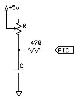
The command works by using the microcontroller pin to discharge the capacitor, then measuring the time taken for the capacitor to charge again through the resistor.
The value for the capacitor must be adjusted depending on the size of the variable resistor. The charging time needs to be approximately 2.5 ms when the resistor is at its maximum value. For a typical 50 k potentiometer or LDR, a 50 nf capacitor is required.
This command should be used carefully. Each time it is inserted, 20 words of program memory are used on the chip, which as a rough guide is more than 15 times the size of the Set command.
pin is the port connected to the circuit. The direction of the pin will be dealt with by the Pot command.
output is the name of the variable that will receive the value.
Example 1:
'This program will beep whenever a shadow is detected
'A potentiometer is used to adjust the threshold
#chip 16F628A, 4
#define ADJUST PORTB.0
#define LDR PORTB.1
#define SoundOut PORTB.2
Dir SoundOut Out
Do
Pot ADJUST, Threshold
Pot LDR, LightLevel
If LightLevel > Threshold Then
Tone 1000, 100
End If
Loop
Example 2:
This program is an implementation of the capacitor and resistor principle using the chips internal capacitor and the internal pullup resistor.
The will test the state of the GPIO.3 port by using these internal components, and, after the charge state has been complete the LED PWM will represent the detected value of signal on the GPIO.3 port.
It should be note that GCBASIC will set the DIRection of GPIO.2 and GPIO.3 automatically. And, this solution is specific to the 12F509 and therefore the 12F509 register called NOT_GPPU may be different on another chip.
#chip 12F509
#option Explicit
;Defines (Constants)
#define PWM_Out1 GPIO.2
;Variables
Dim TimeCount As byte
Dim OPTION_REG as byte
Do Forever
NOT_GPPU = Off
Wait 1 ms
NOT_GPPU = On
TimeCount = 0
'Do while held high by the internal capacitance
Do While GPIO.3 = 1
TimeCount = TimeCount + 1
If TimeCount = 255 Then
Exit Do
End If
Loop
PWMout 1, TimeCount, 5
Loop
See also ladyada.net/library/rccalc.html or cvs1.uklinux.net/cgi-bin/calculators/time_const.cgi for calculating capacitor value. These sites are not associated with GCBASIC.
PulseOut
Syntax:
PulseOut pin, time units
Command Availability:
Available on all microcontrollers.
Explanation:
The PulseOut command will set the specified pin high, wait for the specified amount of time, and then set the pin low again. The pin is specified in the same way as it is for the Set command, and the time is the same as for the Wait command.
Example:
'This program flashes an LED on GPIO.0 using PulseOut
#chip 12F629, 4
'The DIRection of the port is set to show the command. It is not required to set the DIRection when using the PulseOut command.
Dir GPIO.0 Out
Do
PulseOut GPIO.0, 1 sec 'Turn LED on for 1 sec
Wait 1 sec 'Wait 1 sec with LED off
Loop
PulseOutInv
Syntax:
PulseOutInv pin, time units
Command Availability:
Available on all microcontrollers.
Explanation:
The PulseOutInv command will set the specified pin low, wait for the specified amount of time, and then set the pin high. The pin is specified in the same way as it is for the Set command, and the time is the same as for the Wait command.
Example:
'This program flashes an LED on GPIO.0 using PulseOutInv
#chip 12F629, 4
Dir GPIO.0 Out
Do
PulseOutInv GPIO.0, 1 sec 'Turn LED off for 1 sec
Wait 1 sec 'Wait 1 sec with LED on
Loop
PulseIn
Syntax:
PulseIn pin, user_variable, time units
Command Availability:
Available on all microcontrollers.
Explanation:
The PulseIn command will monitor the specified pin when the pin is high, and then measure the high time. It will store the time in the user variable.
The user variable must be a WORD if returned units are expected to be > 255 (Example: Pulse is 500 ms)
PulseIn is not recommended for accurate measurement of microsecond pulses
Example:
#chip 12F629, 4
Dir GPIO.0 In
Dim TimeResult as WORD
Do while GPIO.0 = Off 'Wait for next positive edge to start measuring
Loop
Pulsein GPIO.0, TimeResult, ms
PulseInInv
Syntax:
PulseInInv pin, user_variable, time units
Command Availability:
Available on all microcontrollers.
Explanation:
The PulseIn command will monitor the specified pin when the pin is low, and then measure the low time. It will store the time in the user variable.
The user variable must be a WORD if returned units are expected to be > 255 (Example: Pulse is 500 ms)
PulseInInv is not recommended for accurate measurement of microsecond pulses.
Example:
#chip 12F629, 4
Dir GPIO.0 In
Dim TimeResult as WORD
Do while GPIO.0 = On 'Wait for next negative edge to start measuring
Loop
PulseinInv GPIO.0, TimeResult, ms
Peek
Syntax:
OutputVariable = Peek (location)
Command Availability:
Available on all microcontrollers.
Explanation:
The Peek function is used to read information from the on-chip RAM of the microcontroller.
location is a word variable that gives the address to read. The exact range of valid values varies from chip to chip.
This command should not normally be used, as it will make the porting of code to another chip very difficult.
Example #1 :
'This program will read and check a value from PORTA
'This specific peek will only work on some microcontrollers
Temp = Peek(5)
IF Temp.2 ON THEN SET green ON
IF Temp.2 OFF THEN SET red ON
Example #2
' This subroutine will toggle the pin state.
' You must change the parameters for your specific chip.
' Usage as show in examples below.
'
' Toggle @PORTE, 2 ' equates to RE1.
' Wait 100 ms
' Toggle @PORTE, 2
' Wait 100 ms
' Port , Pin address in Binary
' Pin0 = 1
' Pin1 = 2
' Pin2 = 4
' Pin3 = 8
'
' You can toggle any number of pins.
' Toggle @PORTE, 0x55
Sub Toggle ( In DestPort As word, In DestBit )
Poke DestPort, Peek(DestPort) xor DestBit
End sub
See Also Poke
Poke
Syntax:
Poke(location, value)
Command Availability:
Available on all microcontrollers.
Explanation:
The Poke command is used to write information to the on-chip RAM of the microcontroller.
location is a word variable that gives the address to write. The exact range of valid values varies from chip to chip.
value is the data to write to the location.
This command should not normally be used, as it will make the porting of code to another chip very difficult.
Example 1:
'This program will set all of the PORTB pins high
POKE (6, 255)
Example 2:
;Chip Settings
#chip 16F88
Dir PORTB out
Do Forever
FlashPin @PORTB, 8
Wait 1 s
Loop
Sub FlashPin (In DestVar As word, In DestBit)
Poke DestVar, Peek(DestVar) Or DestBit
Wait 1 s
Poke DestVar, Peek(DestVar) And Not DestBit
End Sub
Using @ before the name of a variable (including a special function register) will give you the address of that variable, which can then be stored in a word variable and used by Peek and Poke to indirectly access the location.
See Also Peek
Weak Pullups
Weak pullups provide a method within many microcontrollers such as the Atmel AVR and Microchip PIC microcontrollers to support internal/selectable pull-ups for convenience and reduced parts count.
If you require Weak pullups these internal pullups can provide a simple solution. For example, you can use them to ground input pins with a switch closure - with the pullup enabled, the pin is held in a high state until the input line pulls it to ground. Be aware of possible EMI interference and also make sure to use a debounce routine.
If you need your weak pullups to exactly control current (rare for most microcontroller applications), then you should consider 10k resistors (5V/10K = 500uA) Why? If you review in the microcontroller data sheet, there is no resistance given for the weak pullups. That is because they are not weak pull-resistors they are weak pullups consisting of what appear to be high-resistance channel pFETs. Their channel resistance will vary with temperature and between parts; not easy to characterize.
The data sheet gives a current range for the internals as 50-400uA (at 5V).
PORTs can have an individually controlled weak internal pullup. When set, each bit of the appropriate Microchip PIC register enables the corresponding pin pullup. There is a master bit within a specific register bit that enables pullups on all pins which also have their corresponding weak pull bit set. Also when set, there is a weak pull register bit to disable all weak pullups.
The weak pullup is automatically turned off when the port pin is configured as an output. The pullups are disabled on a Power-on Reset.
Each specific microcontroller has different registers/bits for this functionality.
You should review the datasheet for the method for a specific microcontroller.
The following code demonstrates how to set the weak pullups available on port B of an 18F25K20.
Example:
'A program to show the use of weak pullups on portb.
'Set chip model
#chip 18F25k20,16 'at 16 MHz
#config MCLR = Off
Set RBPU = 0 'enabling Port B pullups in general.
SET WPUB1 = 1 'portb.1 pulled up
Set WPUB2 = 1 'portb.2
Set WPUB3 = 1 'portb.3
Set WPUB4 = 1 'portb.4
Dir Portb in
Dir Portc out
do
portc.1 = portb.1 'in pin 22, out pin 12
portc.2 = portb.2 'in pin 23, out pin 13
portc.3 = portb.3 'in pin 24, out pin 14
portc.4 = portb.4 'in pin 25, out pin 15
loop 'jump back to the start of the program
'main line ends here
end
Also, see I2C Slave Hardware for an example using a 16F microcontroller.
Maths
This is the Maths section of the Help file. Please refer the sub-sections for details using the contents/folder view.
Abs
Syntax:
integer_variable = Abs( integer_variable )
Command Availability:
Available on all microcontrollers.
Explanation:
The Abs function will compute the absolute value of a integer number therefore in the range of −32767 to +32767.
Example:
absolute_value = Abs( -127 ) ' Will return 127
absolute_value = Abs( 127 ) ' Will return 127 also. :-)
Average
Syntax:
integer_variable = Average(byte_variable1 , byte_variable2)
Command Availability:
Available on all microcontrollers.
Explanation:
A function that returns the average of two numbers. This only supports byte variables.
Provides a very fast way to calculate the average of two 8 bit numbers.
Example:
average_value = Average(8,4) ' Will return 6
Difference
Syntax:
Difference ( word_variable1 , word_variable2 )orDifference ( byte_variable1 , byte_variable2 )
Command Availability:
Available on all microcontrollers.
Explanation:
A function that returns the difference between of two numbers. This only supports byte or word variables.
Example:
Difference( 8 ,4 ) ' Will return 4
Difference( 0xff01 , 0xfffa ) ' Will return 0xf9 or 249d
Int
Syntax:
integer_variable = Int( single_variable )
Command Availability:
Available on all microcontrollers.
Explanation:
The Int function will compute the integer value of an integer number therefore will return the range of single variable.
Example:
integer_value = Int( _singlevariable_ ) ' Will return the range of single variable.
Logarithms
Explanation:
GCBASIC support logarithmic functions through the include file <maths.h>.
These functions compute base 2, base e and base 10 logarithms accurate to 2 decimal places, +/- 0.01.
The values returned are fixed-point numbers, with two decimal places assumed on the right. Or if you prefer, think of the values as being scaled up by 100.
The input arguments are word-sized integers, 1 to 65535. Remember, logarithms are not defined for non-positive numbers. It is the calling program’s responsibility to avoid these. Output values are also word-sized.
Local variables consume 9 bytes, while the function parameters consume another 4 bytes, for a grand total of 13 bytes of RAM used. The lookup table takes 35 words of program memory.
Supported in <MATHS.H>
Log2
Syntax:
returned_word_variable = Log2 ( word_value )
Command Availability:
Available on all microcontrollers.
Explanation:
The Log2 command will return the base-2 logarithm, to 2 decimal places.
The values returned are fixed-point numbers, with two decimal places assumed on the right. or if you prefer, think of the values as being scaled up by 100.
Example:
dim log_value as word
log_value = log2 ( 10 ) 'return 3321 equate to 3.321
Supported in <MATHS.H>
Loge
Syntax:
returned_word_variable = Loge ( word_value )
Command Availability:
Available on all microcontrollers.
Explanation:
The Loge command will return the base-e logarithm, to 2 decimal places.
The values returned are fixed-point numbers, with two decimal places assumed on the right. or if you prefer, think of the values as being scaled up by 100.
Example:
dim log_value as word
log_value = loge ( 10 )
Supported in <MATHS.H>
Log10
Syntax:
returned_word_variable = Log10 (word_value)
Command Availability:
Available on all microcontrollers.
Explanation:
The Log10 command will return the base-10 logarithm, to 2 decimal places.
The values returned are fixed-point numbers, with two decimal places assumed on the right. or if you prefer, think of the values as being scaled up by 100.
Example:
dim log_value as word
log_value = log10 ( 10 ) 'return 230 equate to 2.30
Supported in <MATHS.H>
Power
Syntax:
power( base, exponent )
Explanation:
This function raises a base to an exponent, i.e, power(base,exponent). Calculation powers will become large, in terms of long numbers, you must ensure the program manage numbers remain within range of the defined variables.
The base and exponent are Byte sized numbers in this method.
The returned result is a Long.
Non-negative numbers are assumed throughout.
Note: 0 raised to 0 is meaningless and should be avoided, but, any other non-zero base raised to 0 is handled correctly.
Example:
;Thomas Henry -- 5/2/2014
;----- Configuration
#chip 16F88, 8 ;PIC16F88 running at 8 MHz
#config mclr=off ;reset handled internally
#include <maths.h> ;required maths.h
;----- Constants
#define LCD_IO 4 ;4-bit mode
#define LCD_WIDTH 20 ;specified lcd width for clarity only. 20 is the default width
#define LCD_RS PortB.2 ;pin 8 is LCD Register Select
#define LCD_Enable PortB.3 ;pin 9 is LCD Enable
#define LCD_DB4 PortB.4 ;DB4 on pin 10
#define LCD_DB5 PortB.5 ;DB5 on pin 11
#define LCD_DB6 PortB.6 ;DB6 on pin 12
#define LCD_DB7 PortB.7 ;DB7 on pin 13
#define LCD_NO_RW 1 ;Ground the RW line on LCD
;----- Variables
dim i, j as byte
;----- Program
dir PortB out ;all outputs to the LCD
for i = 1 to 10 ;do all the way from
for j = 0 to 9 ;1^0 on up to 10^9
cls
print i
print "^"
print j
print "="
locate 1,0
print power(i,j) ;here's the invocation
wait 1 S
next j
next i
Supported in <MATHS.H>
RoundSingle
Syntax:
rounded_single_value = RoundSingle( single_variable )
Command Availability:
Available on all microcontrollers.
Explanation:
The RoundSingle function will return a floating point number that is a rounded version of the specified number.
This operates the same as Microsoft floor().
Example:
rounded_single_value = RoundSingle( _singlevariable_ ) ' Will return the range of single variable.
Scale
Syntax:
integer_variable = Scale (value_word , fromLow_integer , fromHigh_integer , toLow_integer , toHigh_integer [, calibration_integer] )
Command Availability:
Available on all microcontrollers. The parameters are:
value: the number to scale. A value between 0 and 0xFFFFF - all values passed will be treated as Word variables.
fromLow: the lower bound of the value’s current range. An Integer value between -32767 and 32767.
fromHigh: the upper bound of the value’s current range. An Integer value between -32767 and 32767.
toLow: the lower bound of the value’s target range. An Integer value between -32767 and 32767.
toHigh: the upper bound of the value’s target range. An Integer value between -32767 and 32767.
calibration: optional calibration offset value. An Integer value between -32767 and 32767.
This is also an overloaded method. You can also use word variables to provide a returned result of 0-65535.
word_variable = Scale (value_word , fromLow_word , fromHigh_word , toLow_wordr , toHigh_word [, calibration_integer] )
Available on all microcontrollers. The parameters are:
value: the number to scale. A value between 0 and 0xFFFFF - all values passed will be treated as Word variables.
fromLow: the lower bound of the value’s current range. A word value.
fromHigh: the upper bound of the value’s current range. A word value.
toLow: the lower bound of the value’s target range. A word value.
toHigh: the upper bound of the value’s target range. A word value.
calibration: optional calibration offset value. An Integer value between -32767 and 32767.
Explanation:
Scales, re-maps, a number from one range to another. That is, a value of fromLow would gets scaled to toLow, a value of fromHigh to toHigh, values in-between to values in-between, etc.
The method does not constrain values to within the integer range returned, because out-of-range values are sometimes intended and useful.
Note that the "lower bounds" of either range may be larger or smaller than the "upper bounds" so the scale() method may be used to reverse a range of numbers, for example:
my_newvalue = scale ( ReadAD10(An0) , 0, 1023, 135, 270)
The method also handles negative integer numbers well, so that this example:
my_newvalue = scale(ReadAD(An0), 0, 255, 50, -100);
This method is similar to the Ardunio Map() function.
Sqrt
Syntax:
word_variable = sqrt ( word )
Explanation:
A square root routine for GCBASIC. The function only involves bit shifting, addition and subtraction, which makes it fast and efficient.
This method required a word variable as the input and a word variable as the output. The method will handle arguments of up to 4294.
Command Availability:
Available on all microcontrollers, required MATHS.H include file.
Example:
;Demo: Show the first 100 square roots to 2 decimal places.
;This uses the maths.h include file.
;----- Configuration
#chip 16F88, 8 ;PIC16F88 running at 8 MHz
#config mclr=off ;reset handled internally
#include <maths.h> ;required maths.h
;----- Constants
#define LCD_IO 4 ;4-bit mode
#define LCD_WIDTH 20 ;specified lcd width for clarity only. 20 is the default width
#define LCD_RS PortB.2 ;pin 8 is LCD Register Select
#define LCD_Enable PortB.3 ;pin 9 is LCD Enable
#define LCD_DB4 PortB.4 ;DB4 on pin 10
#define LCD_DB5 PortB.5 ;DB5 on pin 11
#define LCD_DB6 PortB.6 ;DB6 on pin 12
#define LCD_DB7 PortB.7 ;DB7 on pin 13
#define LCD_NO_RW 1 ;ground the RW line on LCD
;----- Variables
dim length as byte
dim i as word
dim valStr, outStr as string
;----- Program
dir PortB out ;all outputs to the LCD
for i = 0 to 100 ;print first 100 square roots
cls
print "sqrt("
print i
print ")="
valStr = str(sqrt(i)) ;format decimal nicely
length = len(valStr)
select case length
case 1:
outStr = "0.00" ;zero case
case 3:
outStr = left(valStr,1)+ "."+right(valStr,2)
case 4:
outStr = left(valStr,2)+ "."+right(valStr,2)
case 5:
outStr = left(valStr,3)+ "."+right(valStr,2)
end select
print outStr ;display results
wait 2 S
next i
Supported in <MATHS.H>
Trigonometry Sine, Cosine and Tangent
Syntax:
integer_variable = sin( integer_variable )
integer_variable = cos( integer_variable )
integer_variable = tan( integer_variable )
Explanation:
GCBASIC supports Three Primary Trigonometric Functions
GCBASIC supports the following functions, sin(x), cos(x), tan(x), where x is a signed integer representing an angle measured in a whole number of degrees. The output values are also integers, represented as fixed point decimal fractions.
Details:
The sine, cosine and tangent functions are available for your programs simply by including the header file offering the precision you need.
#INCLUDE <TRIG2PLACES.H> gives two decimal places
#INCLUDE <TRIG3PLACES.H> gives three decimal places
#INCLUDE <TRIG4PLACES.H> gives four decimal places
In fixed point representation, the decimal point is assumed. For example, with two places of accuracy, sin(60) returns 87, which you would interpret as 0.87. With three places, 866 is returned, to be interpreted as 0.866, and so on. Another way of thinking of this is to consider the two-place values as scaled up by 100, the three-place values scaled up by 1000 and the four-place values scaled up by 10,000.
Sine and Cosine are always defined, but remember that tangent fails to exist at 90 degrees, 270 degrees and all their coterminal angles. It is the responsibility of the calling program to avoid these special values.
Note that the tangent function is not available to four decimal places, since its value grows so rapidly, exceeding what the Integer data type can represent.
These routines are completely general. The input argument may be positive, negative or zero, with no restriction on the size. Further observe that lookup tables are used, so the routines are very fast, efficient and accurate.
Example: Show the trigonometric values to three decimal places.
;----- Configuration
#CHIP 16F88, 8 ;PIC16F88 RUNNING AT 8 MHZ
#CONFIG MCLR=OFF ;RESET HANDLED INTERNALLY
#INCLUDE <TRIG3PLACES.H>
;----- Constants
#define LCD_IO 4 ;4-bit mode
#define LCD_WIDTH 20 ;specified lcd width for clarity only. 20 is the default width
#define LCD_RS PortB.2 ;pin 8 is LCD Register Select
#define LCD_Enable PortB.3 ;pin 9 is LCD Enable
#define LCD_DB4 PortB.4 ;DB4 on pin 10
#define LCD_DB5 PortB.5 ;DB5 on pin 11
#define LCD_DB6 PortB.6 ;DB6a on pin 12
#define LCD_DB7 PortB.7 ;DB7 on pin 13
#define LCD_NO_RW 1 ;ground the RW line on LCD
;----- Variables
dim ii as integer
dim outStr, valStr as string
;----- Program
dir PortB out ;all outputs to the LCD
for ii = -720 to 720 ;arguments from -720 to 720
cls
print "sin(" ;print the label
print ii ;and the argument
print ")=" ;and closing parenthesis
locate 1,0
printTrig(sin(ii)) ;print value of the sine
wait 500 mS ;pause to view
cls ;do likewise for cosine
print "cos("
print ii
print ")="
locate 1,0
printTrig(cos(ii))
wait 500 mS ;pause to view
cls ;do likewise for tangent
print "tan("
print ii
print ")="
locate 1,0
printTrig(tan(ii))
wait 500 mS ;pause to view
next i
sub printTrig(in value as integer)
;print decently formatted trig results
outStr = "" ;assume positive (no sign)
if value < 0 then ;handle negatives
outStr = "-" ;prefix a minus sign
value = -1 * value ;but work with positives
end if
valStr = str(value)
length = len(valStr)
select case length
case 1:
outStr = outStr + "0.00" + valStr
case 2:
outStr = outStr + "0.0" + valStr
case 3:
outStr = outStr + "0." + valStr
case 4:
outStr = outStr + left(valStr,1) + "." + right(valStr,3)
case 5:
outStr = outStr + left(valStr,2) + "." + right(valStr,3)
end select
print outStr
end sub
Trigonometry ATAN
Syntax:
#include <maths.h>
integer_variable = ATan (_x_vector_,_y_vector_)
Explanation:
GCBASIC supports the trigonometric function for ATan.
Details:
GCBASIC supports the following functions ATan( x, y) where x and y are the vectors. The function returns an Integer result representing the angle measured in a whole number of degrees.
The function also returns a global byte variable NegFlag with returns the quadrant of the angle.
Quadrant 1 = 0 to 89 Quadrant 2 = 90 to 179 Quadrant 3 = 180 to 269 Quadrant 4 = 270 to 359
This ATan function is a fast XY vector to integer degree algorithm developed in Jan 2011, see www.RomanBlack.com and see http://www.romanblack.com/integer_degree.htm
The function converts any XY vectors including 0 to a degree value that should be within +/- 1 degree of the accurate value without needing large slow trig functions like ArcTan() or ArcCos().
At least one of the X or Y values must be non-zero. This is the full version, for all 4 quadrants and will generate the angle in integer degrees from 0-360. Any values of X and Y are usable including negative values provided they are between -1456 and 1456 so the 16bit multiply does not overflow.
Peripheral Pin Select
This is the Peripheral Pin Select section of the Help file. Please refer the sub-sections for details using the contents/folder view.
Peripheral Pin Select for Microchip microcontrollers.
Introduction:
Peripheral Pin Select (PPS) enables the digital peripheral I/O pins to be changed to support mapping of external pins to different pins.
In older 8-bit Microchip devices, a peripheral was hard-wired to a specific pin (example: PWM1 output on pin RC5).
PPS allows you to choose from a number of output and input pins to connect to the digital peripheral.
This can be extremely useful for routing circuit boards.
There are cases where a change of I/O position can make a circuit board easier to route Sometimes mistakes are found too late to fix so having the option to change a pinout mapping in software rather than creating a new printed circuit board can be very helpful.
You must use the command UnLockPPS to enable setting of the PPS if the PPS have been previously locked, and, you can, optionally, use LockPPS to prevent unintentional change to PPS settings.
GCBASIC includes these two macros to ensure this process is handled correctly.
Also, see http://microchip.wikidot.com/8bit:pps for more information.
Example:
'Please check configuration before using on an alternative microcontroller.
#chip 16f18855,32
#option explicit
'Set the PPS of the I2C and the RS232 ports.
#startup InitPPS, 85
Sub InitPPS
LOCKPPS
RC0PPS = 0x0010 'RC0->EUSART:TX;
RXPPS = 0x0011 'RC1->EUSART:RX;
SSP1CLKPPS = 0x14 'RC3->MSSP1:SCL1;
SSP1DATPPS = 0x13 'RC4->MSSP1:SDA1;
RC3PPS = 0x15 'RC3->MSSP1:SCL1;
RC4PPS = 0x14 'RC4->MSSP1:SDA1;
UnLockPPS
End Sub
UnLockPPS
Syntax:
UNLOCKPPS
Explanation:
Peripheral Pin Select (PPS) has an operation mode in which all input and output selections can be prevented to stop inadvertent changes.
PPS selections are unlocked by setting by the use of the UnLockPPS command.
Using this command will ensure the special sequence of Microchip assembler is handled correctly.
Command Availability:
Available on all Microchip microcontrollers only.
#chip 16f18855,32
#option explicit
'Set the PPS of the I2C and the RS232 ports.
#startup InitPPS, 85
Sub InitPPS
UNLOCKPPS
RC0PPS = 0x0010 'RC0->EUSART:TX;
RXPPS = 0x0011 'RC1->EUSART:RX;
SSP1CLKPPS = 0x14 'RC3->MSSP1:SCL1;
SSP1DATPPS = 0x13 'RC4->MSSP1:SDA1;
RC3PPS = 0x15 'RC3->MSSP1:SCL1;
RC4PPS = 0x14 'RC4->MSSP1:SDA1;
LockPPS
End Sub
For more help, see: LockPPS.
LockPPS
Syntax:
LOCKPSS
Explanation:
Peripheral Pin Select (PPS) has an operation mode in which all input and output selections can be prevented to stop inadvertent changes.
PPS selections are locked by setting by the use of the LockPPS command.
Using this command will ensure the special sequence of Microchip assembler is handled correctly.
Command Availability:
Available on all Microchip microcontrollers only.
#chip 16f18855,32
#option explicit
'Set the PPS of the I2C and the RS232 ports.
#startup InitPPS, 85
Sub InitPPS
UNLOCKPPS
RC0PPS = 0x0010 'RC0->EUSART:TX;
RXPPS = 0x0011 'RC1->EUSART:RX;
SSP1CLKPPS = 0x14 'RC3->MSSP1:SCL1;
SSP1DATPPS = 0x13 'RC4->MSSP1:SDA1;
RC3PPS = 0x15 'RC3->MSSP1:SCL1;
RC4PPS = 0x14 'RC4->MSSP1:SDA1;
LOCKPPS
End Sub
For more help, see: UnlockPPS.
Compiler Directives
This is the Compiler Directives section of the Help file. Please refer the sub-sections for details using the contents/folder view.
#asmraw
Syntax:
#asmraw [label]
#asmraw [Mnemonics | Directives | Macros] [Operands] ['comments]
for ASM blocks use
#asmraw[
[label]
[Mnemonics | Directives | Macros] [Operands] ['comments]
#asmraw]
Explanation:
The #asmraw directive is used to specify the assembly that GCBASIC will use.
Anything following this directive will be inserted into ASM source file with no changes other than trimming spaces - no replacement of constants.
Assembly is a programming language you may use to develop the source code for your application.
The directive must conform to the following basic guidelines.
Each line of the source file may contain up to four types of information:
• Labels
• Mnemonics, Directives and Macros
• Operands
• Comments
The order and position of these are important. For ease of debugging, it is recommended that labels start in column one and mnemonics start in column two or beyond. Operands follow the mnemonic.
Comments may follow the operands, mnemonics or labels, and can start in any column. The maximum column width is 255 characters.
White space or a colon must separate the label and the mnemonic, and white space must separate the mnemonic and the operand(s). Multiple operands must be separated by commas.
White space is one or more spaces or tabs. White space is used to separate pieces of a source line. White space should be used to make your code easier for people to read.
Example 1
#asmraw lds SysValueCopy,TCCR0B
#asmraw andi SysValueCopy, 0xf8
#asmraw inc SysValueCopy
#asmraw sts TCCR0B, SysValueCopy
Example 2
#asmraw[
lds SysValueCopy,TCCR0B
andi SysValueCopy, 0xf8
inc SysValueCopy
sts TCCR0B, SysValueCopy
#asmraw]
This example will generate the following in the ASM source file.
lds SysValueCopy,TCCR0B
andi SysValueCopy, 0xf8
inc SysValueCopy
sts TCCR0B, SysValueCopy
#chip
Syntax:
#chip model, frequency
#chip model, frequency / numeric constant
Explanation:
The #chip directive is used to specify the chip model and frequency that GCBASIC will use.
The model is the specific microcontroller - examples are "16F819".
The frequency is the frequency of the chip in MHz, and is required for the delay and PWM routines.
The following constants simplify setting specific frequencies.
31k, 32.768K, 125k, 250k or 500k. Any of these constant can be used. As shown in the example below.
If frequency is not present the compiler will select a frequency default frequency that should work for the microcontroller.
If numeric constant is specified then the compiler will complete a simple math calculation to determine the frequency. The only supported math instruction is divide.
-
If the chip has an internal oscillator, the compiler will use that and pick the highest frequency it supports.
-
If the chip does not have an internal oscillator, then GCBASIC will assume that the chip is being run at its maximum possible clock frequency using an external crystal.
-
If you are using an external crystal then you must specify a chip frequency.
When using an AVR:
-
There is no need to specify "AT" before the name.
-
Only AVRDX chips support setting the internal frequency using the
frequencystatement. -
megaAVR assumes an external oscillator, and, therefore the
frequencymust match the external oscillator frequency. For Arduino products this is typically 16Mhz
When using a LGT:
-
Only LGT support setting the internal frequency using the
frequencystatement.
Examples:
#chip 12F509, 4
#chip 18F4550, 48
#chip 16F88, 0.125
#chip tiny2313, 1
#chip mega8, 16
#chip 12f1840, 31k
#chip 12f1840, 500k
#chip 12f1840, 250k
#chip 12f1840, 125k
#chip lgt8x328p, 4
#chip tiny3127, 16 / 48
'Select the internal low frequency oscillator. The microcontroller must have a low frequency oscillator option. The internal oscillator is automatically selected on PIC.
#chip 16f18326, 31k
'Select the external SOSC clock source.
#chip 16f18855, 32.768k
#config osc=SOSC
Setting Other Clock frequencies: Some alternative compilers allow value of the clock frequency to be set with the numerical value in Hertz (i.e. 24576000). This can be useful when using the clock frequencies other than standard frequencies.
GCBASIC requires clock frequencys to be specified in MHz, but will accept decimal points. For example, if you wanted to run a 16F1827 at 24576000 Hz, you would write the following:
#chip 16F1827, 24.576
GCBASIC support for microcontrollers:
Each microcontroller has a microcontroller data file. This file is located in \GCBasic\chipdata\ folder when installed.
An example is 12F1840.dat
The there are two sections in the microcontroller data file that control the "chip frequency", they are:
*[ChipData]* and *[ConfigOps]*
ChipData section
The ChipData section for 12F1840 microcontroller. The 12F1840 is used an example
[ChipData]
Prog=4096
EEPROM=256
RAM=256
I/O=6
ADC=4
MaxMHz=32
IntOsc=32, 16, 8, 4, 2, 1, 0.5, 0.25, 0.125
31kSupport=INTOSC,OSCCON,2
Pins=8
Family=15
ConfigWords=2
PSP=0
MaxAddress=4095
The IntOsc line specifies the supported internal clock frequencies - The 12F1840 microcontroller supports nine internal frequencies (ChipMHz). #Chip is used as follows: The 31kSupport line specifies the chip supports 31k for internal clock frequency.
#chip 12F1840, 32
A ChipMHz of 32 does two things.
-
When using the internal oscillator, it tells the compiler to set the chip clock frequency (FOSC) to 32MHz
-
It tells the compiler to calculate all delays (wait times) based upon FOSC of 32 MHz. Unlike Picaxe Basic (and other compilers) GCBASIC delays ("wait") are correct regardless of the setting of FOSC. If you set the internal oscillator to 4 MHz a "wait 1 ms" will still be 1 ms.
If you set chipMHz to something other than the valid options in the [ChipData] IntOsc section of the microcontroller specific dat file, then, the compiler assumes that you are using an external oscillator and will calculate the delays according to the value you use. The wait times will be incorrect if you are not using an external oscillator at the same frequency as ChipMhz.
Example: #chip 12F1840, 12
Since "12" is not a valid internal osc frequency, the microcontroller FOSC will default to 8 MHz because there is no external crystal installed. However, the wait times will be incorrect as they will be calculated by the compiler based upon a 12 Mhz clock.
ConfigOps section
The [ConfigOps] section of 12F1840.dat is towards the end of the chip data file. For the 12F1840 is looks like this
[ConfigOps]
OSC=LP,XT,HS,EXTRC,INTOSC,ECL,ECM,ECH
WDTE=OFF,SWDTEN,NSLEEP,ON
PWRTE=ON,OFF
MCLRE=OFF,ON
CP=ON,OFF
CPD=ON,OFF
BOREN=OFF,SBODEN,NSLEEP,ON
CLKOUTEN=ON,OFF
IESO=OFF,ON
FCMEN=OFF,ON
WRT=ALL,HALF,BOOT,OFF
PLLEN=OFF,ON
STVREN=OFF,ON
BORV=HI,LO,19
LVP=OFF,ON
OSC specifies which oscillator options are available for the specific microcontroller.
INTOSC is the internal oscillator. All others are some form of external clock source.
PLLEN sets the internal Phase Lock Loop either on or off. With this chip the default clock frequency is 8 Mhz. The PLL multiplies this by 4. So to get 32 Mhz the basic internal oscillator will be 8 Mhz then multiplied by 4. For 16 MHz it wil be 4 multiplied by 2.
GCB sets the PLL automatically, so this option should generally be left alone. IF PLLEN is set to ON, then GCB may not be able to set the correct frewuency of the internal oscillator. Only set PLL = ON if you know what you are doing.
It is a good practice to set the oscillator source in #config at the beginning of your code when you are not using the internal oscillator. This prevents potential errors. Example:
#Chip 12F1840, 16
#Config OSC = INTOSC 'This is normally not required as the internal oscillator is the default oscillator.
In this example above, GCBASIC will automatically set the necessary OSC bits for the microcontroller. Frequency bits will be set to 4 MHz and the PLL will be turned on and wait times will be calculated on an FOSC of 16.
You can set the clock to other frequencies but you have to put the PIC into EC or External Clock mode and then supply that specific clock frequency to the OSC1 pin.
There are three EC modes on the PIC12F1840:
ECL - 0 MHz - 0.5 MHz
ECM - 0.5 MHz - 4 MHz
ECH = 4 MHz - 32MHz
Example: For a 2.1 MHz clock you would need to set the #config and the clock frequency, and, provide the OSC1 pin with a 2.1 MHz signal.
#chip 12f1840,2.1
#config OSC = ECM
Notes
When "#config osc=" is not specified in the source code, most microcontrollers will default to an external oscillator source. This means at runtime the chip is expecting an external clock signal. If the external clock signal is not present, the chip detects a "failure" of the external clock and will "falls back" to the default internal oscillator setting.
The PLLEN bit defaults to OFF. The PLL is enabled depending upon the ChipMhz in #Chip xxxxxx, ChipMhz.
The GCBASIC defaults - This is how the bits are set if there is no #config in the source code, GCBASIC does set certain bits. To examine what bits are set on a particular chip you can omit #config in the source code, thenm compile the code and then use "Open ASM" in the GCBASIC IDE. The bits that are set will be in the config section. All other bits ( those not specifically set) with #Config will be at the POR setting as described below, The POR settings are shown in the datasheet for each microcontroller.
Currently GCBASIC sets the LVP bit OFF by default on many chips. This does not affect normal HV programming like a with a PicKit3. The default of LVP = OFF will prevent the microcontroller from being programmed with Low Voltage Programmer. This means that if a PIC microcontroller has previously been programmed with with "LVP = OFF", then it must be erased or reprogrammed with LVP = ON using a HVP programmer prior to using certain programming devices e.g. Curiosity development boards, or "NS" programmers as these required that LVP = ON.
When LVP = ON, the MCLR pin is automatically set to EXTERNAL MCLR. This means that the MCLRE pin CANNOT be sue for general purpose I/O functions.
The native POR (Power On Reset) defaults. This is the state of the config bits after Power on if the ASM code has no configuration entries or on a blank factory chip. The only way to power up in this state with GCB code is to use " #option NoConfig" in the GCBASIC source code.
#config
Syntax:
#config option1, option2, ... , optionN
Explanation:
The #config directive is used to specify configuration options for the chip. There is a detailed explanation of #config in the Configuration section of help.
See Also Configuration
#DEFINE
Syntax:
#DEFINE NAME [String]
or
#DEFINE NAME [ = String]
Explanation:
#DEFINE allows to declare string-based preprocessor constants.
This directive defines a text substitution string. Wherever name is encountered in the program or assembly code, string will be substituted.
The expansion is done recursively, until there is nothing more to expand and the compiler can continue analyzing the resulting code.
The use of an existing constant is supported. The order of constants when using an existing constant is strict. The constant must exist prior to use.
To ensure evaluation of a calculation. A `=` must be used. This is strict.
#UNDEFINE can be used to make the compiler delete an existing constant.
Using the directive with no string causes a definition of name to be noted internally and may be tested for using the ifdef directive/conditional processing. See the examples below.
Constants defined with this method are available for viewing in the CDF file. Creation of the CDF file is controlled with the Programmer Preferences Utility.
GCBASIC does not support creation of SUBroutine or FUNCTION with this directive.
Examples:
This progress shows the creation of constants, the processing and showing of constants within a script, creation of specific constants within a script and use of constants within a program.
#chip MEGA4809
#option Explicit
// Numeric constants
#define LENGTH 20
#define CONTROL 0x19,7
#define SINGLEPI = 22/7 // evaluated numberic string
#define INTPI = INT(22/7) // evaluated numberic string
#define FACTOREDPI = INT((22/7 - INT(22/7))*1000) // evaluated numberic string
#define LENGTHSQUARED = LENGTH * LENGTH // evaluated numberic string
#define PI 3.142
#define RADIUS 10
#define CIRCUMFERENCECALC = PI * RADIUS // evaluated numberic string, with constant substitution
#define FACTORISEDCIRCUMFERENCE = INT(CIRCUMFERENCECALC*100) // evaluated numberic string, with constant substitution
//String(s) required double quotes and NO `=` assignment
#define MYSTRING "This is a string"
// A string assignment is not required
#define ACONSTANTTHATEXISTS
// Macros are not supported.. just define the sub!
// #define BADPOSITION(XX,YY,ZZ) (YY-(2 * ZZ +XX))
// Unused Constants that are invalid may not report an error until try to use within your program- as in this example
// String assignment with an equal sign will fail. Do not use `=`
#define BADMYSTRING = "This is a string"
#script
//Scripts can modify and manage CONSTANTS
// Warning can be used to show values during compilation
WARNING LENGTH
WARNING CONTROL
WARNING SINGLEPI
WARNING INTPI
WARNING FACTOREDPI
WARNING MYSTRING
If DEF(ACONSTANTTHATEXISTS) Then
WARNING "The constant ACONSTANTTHATEXISTS exists"
End If
// Test for a value in the [ChipData] section of the DAT file. Always has the prefix CHIP
If DEF(CHIPAVRDX) Then
WARNING "This is an AVRDX chip"
End If
// Good practice constant testing, see the code below for BAD and GOOD practice
// Set the constant to 0 we can use this to test for validity
// Use prefix of SCRIPT as this is clear in the program
SCRIPTAN1CONSTANT = 0
If DEF(AVRDX) Then
// Is this an AVRDx chip
If DEF(AIN1) Then
SCRIPTAN1CONSTANT = AIN1
End If
End If
If NODEF(AVRDX) Then
// This is NOT an Avrdx chip
If DEF(AVR) Then
// This is an AVR
SCRIPTAN1CONSTANT = AN1
End If
If DEF(PIC) Then
// This is an AVR
SCRIPTAN1CONSTANT = ANA1
End If
End If
// Now test for validate result
If SCRIPTAN1CONSTANT = 0 Then
WARNING Script has determined that no valid ADC port exists, or, some other message
End If
#endscript
// Some conditional examples
#IF DEF( CONSTANTTHATEXISTS )
//! Cause a compiler error - as the constant exits. Remove comment to test
#ELSE
//! Cause a compiler error - as the constant does not exits. Remove comment to test
#ENDIF
#IFDEF Oneof(CHIP_18F24K40,CHIP_18F25K40,CHIP_18F26K40,CHIP_18F27K40,CHIP_18F45K40,CHIP_18F46K40,CHIP_18F47K40,CHIP_18F65K40,CHIP_18F66K40,CHIP_18LF24K40, CHIP_18LF25K40, CHIP_18LF26K40, CHIP_18LF27K40, CHIP_18LF45K40, CHIP_18LF46K40, CHIP_18LF47K40, CHIP_18F65K40, CHIP_18LF65K40, CHIP_18F66K40, CHIP_18LF66K40, CHIP_18F67K40, CHIP_18LF67K40 )
//~ Do something
#ENDIF
dim myStringVar as String
myStringVar = MYSTRING
// BAD PRACTICE = code is hard to understand
// Use constant test to determine correct ADC to read. Bad practice, see the #SCRIPT section
dim mybyteVar as Byte
#IF DEF(AIN1)
mybyteVar = readAD( AIN1 )
#ELSE
#IF DEF(ANA1)
mybyteVar = readAD( ANA1 )
#ELSE
mybyteVar = readAD( AN1 )
#ENDIF
#ENDIF
// GOOD PRACTICE
dim mybyteVar as Byte
mybyteVar = readAD( SCRIPTAN1CONSTANT )
dim myArray(2)
myArray = CONTROL
See Also DEFINEs
#UNDEFINE
Syntax:
#UNDEFINE existing-symbol
Explanation:
#UNDEFINE Undefines a symbol previously defined with #DEFINE.
Can be used to ensure that a symbol has a limited lifespan and does not conflict with a similar macro definition that may be defined later in the source code.
(Note: #UNDEFINE should not be used to undefine variable or function names used in the current program. The names are needed internally by the compiler and removing them can cause strange and unexpected results.)
See Also Defines
#if
Syntax:
#if Condition
...
[#else]
...
#endif
Explanation:
The #if directive is used to prevent a section of code from compiling unless Condition is true.
Condition has the same syntax as the condition in a normal GCBASIC if command. The only difference is that it uses constants instead of variables and does not use "then".
Example:
'This program will pulse an adjustable number of pins on PORTB
'The number of pins is controlled by the FlashPins constant
#chip 16F88, 8
'The number of pins to flash
#define FlashPins 2
'Initialise
Dir PORTB Out
'Main loop
Do
#if FlashPins >= 1
PulseOut PORTB.0, 250 ms
#endif
#if FlashPins >= 2
PulseOut PORTB.1, 250 ms
#endif
#if FlashPins >= 3
PulseOut PORTB.2, 250 ms
#endif
#if FlashPins >= 4
PulseOut PORTB.3, 250 ms
#endif
Loop
#ifnot
Syntax:
#ifnot Condition
...
[#else]
...
#endif
Explanation:
The #ifnot directive is used to prevent a section of code from compiling unless Condition is false.
Condition has the same syntax as the condition in a normal GCBASIC if command. The only difference is that it uses constants instead of variables and does not use "then".
Example:
'This program will set the constant to true only if NOT a PIC family
#chip 16F88, 8
#ifnot ChipFamily = 14
#define myConstant True
#endif
#ifdef
Syntax:
#ifdef Constant | Constant Value | Var(VariableName)
...
[#else]
...
#endif
Explanation:
The #ifdef directive is used to selectively enable sections of code.
There are several ways in which it can be used:
-
Checking if a constant is defined
-
Checking if a constant is defined and has a particular value
-
Checking if a system variable exists
-
Checking if a system bit has been defined
The advantage of using #ifdef rather than an equivalent series of IF statements is the amount of code that is downloaded to the chip. #ifdef controls what code is compiled and downloaded, IF controls what is run once on the chip. #ifdef should be used whenever the value of a constant is to be checked.
GCBASIC also supports the #ifndef directive - this is the opposite of the #ifdef directive - it will remove code that #ifdef leaves, and vice versa.
Note:
The code in the following sections will not compile, as it is missing #chip directives and Dir commands. It is intended to act as an example only.
Example 1: Enabling code if a constant is defined
#define Blink1
#ifdef Blink1
PulseOut PORTB.0, 1 sec
Wait 1 sec
#endif
#ifdef Blink2
PulseOut PORTB.1, 1 sec
Wait 1 sec
#endif
This code will pulse PORTB.0, but not PORTB.1. This is because Blink1 has been defined, but Blink2 has not. If the line was added at the start of the program, then both pins would be pulsed.
#define Blink2
The value of the constant defined is not important and can be left off of the #define.
Example 2: Enabling code if a constant is defined and has a given value
#define PinsToFlash 2
#ifdef PinsToFlash 1,2,3
PulseOut PORTB.0, 1 sec
#endif
#ifdef PinsToFlash 2,3
PulseOut PORTB.1, 1 sec
#endif
#ifdef PinsToFlash 3
PulseOut PORTB.2, 1 sec
#endif
This program uses a constant called PinsToFlash that controls how many lights are pulsed. PORTB.0 is pulsed when PinsToFlash is equal to 1, 2 or 3, PORTB.1 is pulsed when PinsToFlash equals 2 or 3, and PORTB.2 is flashed when PinsToFlash is 3.
Example 3: Enabling code if a system variable is defined
#ifdef NoVar(ANSEL)
SET ADCON1.PCFG3 OFF
SET ADCON1.PCFG2 ON
SET ADCON1.PCFG1 ON
SET ADCON1.PCFG0 OFF
#endif
#ifdef Var(ANSEL)
ANSEL = 0
#endif
The above section of code has been copied directly from a-d.h. It is used to disable the A/D function of pins, so that they can be used as standard digital I/O ports. If ANSEL is not declared as a system variable for a particular chip, then the program uses ADCON1 to control the port modes. If ANSEL is defined, then the chip is newer and its ports can be set to digital by clearing ANSEL.
Example 4: Enabling code if a system bit is defined
Similar to above, except with Bit and NoBit in the place of Var and NoVar respectively.
#ifndef
Syntax:
#ifndef Constant | Constant Value | Var(VariableName)
...
[#else]
...
#endif
Explanation:
The #ifndef directive is used to selectively enable sections of code. It is the opposite of the #ifdef directive - it will delete code in cases where #ifdef would leave it, and will leave code where #ifdef would delete it.
See the #ifdef article for more information.
#include
Syntax:
#include filename
Explanation:
#include tells GCBASIC to open up another file, read all of the subroutines and constants from it, and then copy them into the current program.
There are two forms of include; absolute and relative.
Absolute is used to refer to files in the ..\GCBASIC\include directory. The name of the file is specified in between < and > symbols. For instance, to include the file srf04.h, the directive is:
#include <srf04.h>
Relative is used to read files in the same folder as the currently selected program. Filenames are given enclosed in quotation marks, such as where mycode.h is the name of the file that is to be read.
#include "mycode.h"
NOTES: It is not essential that the include file name ends in .h - the important thing is that the name given to GCBASIC is the exact name of the file to be included.
Those who are familiar with #include in assembly or C should bear in mind that #include in GCBASIC works differently to #include in most other languages - code is not inserted at the location of the #include, but rather at the end of the current program.
#ignorecompile
Syntax:
#ignorecompile
Explanation:
The #ignorecompile directive is used to control whether a source file can be compiled.
This is can be used to prevent libraries and other source file from being procecessed as a source file for compilation.
This therefore will prevent creation all the GCBASIC outputs file in the folder.
#insert
Syntax:
#insert filename
Explanation:
#insert tells GCBASIC to open up another file, read all of the subroutines and constants from it, and then copy them into the current program at the specific line where the #insert directive is located.
There are two forms of include; absolute and relative.
Absolute is used to refer to files in the ..\GCBASIC\include directory. The name of the file is specified in between < and > symbols. For instance, to include the file toolchain.il, the directive is:
#insert <"toolchain.il">
Relative is used to read files in the same folder as the currently selected program. Filenames are given enclosed in quotation marks, such as where mycode.h is the name of the file that is to be read.
#insert "toolchain.il"
Difference from #include:
This is very different from #include. With #include you can organize constant, method and macro definitions and then use #include directive to add them to any source file. Include files are also useful for incorporating declarations of external variables and complex data types. The types may be defined and named only once in an include file created for that purpose. The compiler will optimise the include files to determine the best order/location in your program.
Using #insert you are determining the location of the code segment. It will be inserted exactly where you specify. The optimisation will only be applied to any methods that you insert but the rest of the code essentially exits at the point of insertion.
#Insert does not support Conversion:
There is no conversion of the inserted file. For conversion use #Include.
If you need to convert a file from an external source then see the Converters section of the Help.
Usage Notes:
The file must exist. An error message is issued if not found. When an error is encountered in the inserted file the error line number is in the format of xxxxyyyy. Where xxxx is the code line number in the user program and the yyyy is the the line number in the inserted file.
An example error message. Where the source insert instruction is on line 6 and the error in the inserted file is on line 4.
An error has been found:
insertexample.gcb (60004): Error: Syntax Error
The message has been logged to the file Errors.txt.
#script
Syntax:
#script
[scriptcommand1]
[scriptcommand2]
...
[scriptcommandn]
#endscript
Explanation:
The #script block is used to create small sections of code which GCBASIC runs during compilation.
A detail explanation and example are included in the Scripts article.
See Also Scripts
#startup
Syntax:
#startup SubName [priority]
Explanation:
#startup is used in include files to automatically insert initialization routines. If a define or subroutine from the file is used in the program, then the specified subroutine will be called.
The priority to #startup support the setting of the priority of the subroutines for all the libraries in a project.
Subroutines will be called in order from smallest to largest priority number.
InitSys has priority 80, lowlevel communication routines have the priority of 90 All other subroutines defaults to 100.
Notes: Limitations on this directive are:
startup may only occur once within a source file.
No parameters can be passed the the subroutine that is specificed.
Example 1:
This example from the hardware I2C library set the subroutine with the priority of 90.
#startup HIC2Init, 90
Example 2:
This example from would be included in user code to ensure the PPS setting are set prior to use of the MSSP or USART.
#chip 16f18855,32
#option explicit
'Set the PPS of the I2C and the RS232 ports.
#startup InitPPS, 85
Sub InitPPS
RC0PPS = 0x0010 'RC0->EUSART:TX;
RXPPS = 0x0011 'RC1->EUSART:RX;
SSP1CLKPPS = 0x14 'RC3->MSSP1:SCL1;
SSP1DATPPS = 0x13 'RC4->MSSP1:SDA1;
RC3PPS = 0x15 'RC3->MSSP1:SCL1;
RC4PPS = 0x14 'RC4->MSSP1:SDA1;
End Sub
#mem
This directive is obsolete.
GCBASIC determines the amount of memory on a chip automatically, and will ignore the #mem directive.
It is recommended that this directive is removed from all programs.
Enum
Overview
Enums in GCBASIC provide a convenient way to define named constants, improving code readability and maintainability. Instead of using raw numeric values, users can define meaningful names for states, modes, or categories.
Syntax:
The Enum keyword allows users to declare an enumeration with automatic assignment of values:
Enum ModbusState [Reset]
MODBUS_IDLE ' Waiting for a new message
MODBUS_SYNC ' Sync with Modbus device address
MODBUS_FUNCTION_CODE ' Identify function code
MODBUS_PROCESS_DATA ' Read incoming data bytes
MODBUS_COMPLETE ' Packet processing finished
End EnumThe optional Reset parameter will start this specific enum at zero. If Reset is not specified then every enum element will be sequentially/uniquely numbered.
Enhanced Compatibility with External Systems
Many protocols, such as Modbus, require specific numeric values for states or function codes. By letting users define their own values, they can align their enums with standardised protocols. The Enum keyword also allows users to declare an enumeration with named constants:
Enum ModbusState
MODBUS_IDLE = 1
MODBUS_SYNC = 0x02
MODBUS_FUNCTION_CODE = 0x03
MODBUS_PROCESS_DATA = MODBUS_FUNCTION_CODE + 1
MODBUS_COMPLETE = INT((30/2)+1)
End EnumUsers can manually assign enumeration values using constants and expressions. Calculations must use the equals sign (=), following #DEFINE rules.
Usage
Users can declare variables of an enum type and assign values directly:
Dim currentState As Byte
currentState = MODBUS_IDLEEnums can be used in conditions for more readable logic:
If currentState = MODBUS_FUNCTION_CODE Then
' Handle function code processing
End IfUsers can also define additional Enum values using constants:
#DEFINE CUSTOM_STATE = MODBUS_PROCESS_DATA + 2
If currentState = CUSTOM_STATE Then
Print "Custom processing step reached."
End IfConversion Support
Enums in GCBASIC can be used in mathematical operations and references to other constants. This allows developers to integrate enums seamlessly into calculations and logical expressions.
Math Operations
Users can use enums in arithmetic expressions since they resolve to numeric values:
Dim nextState As Byte
nextState = MODBUS_SYNC + 1 ' Evaluates to MODBUS_FUNCTION_CODEEnums can also be used in expressions involving comparisons:
If currentState < MODBUS_COMPLETE Then
' Keep processing data
End IfReference to Other Constants
Since enum values are numeric, users can reference them in calculations that involve predefined constants:
#DEFINE MAX_STATE = MODBUS_COMPLETE
If currentState = MAX_STATE Then
Print "Processing complete."
End IfSummary
-
Users can use automatic enumeration values.
-
Users can manually assign enumeration values using constants and calculations.
-
Calculations must use the equals sign (
=), following GCBASIC’s#DEFINErules. -
Enums allow users to define named constants.
-
Values start at
0and increment automatically if not manually assigned. -
Enums improve readability and eliminate the need for magic numbers.
-
Enums can be used in mathematical operations and references to constants.
Other directives
The built-in #defines are used to support the #IFDEF command set are as follows. The table also shows which #defines are supported as string in HSerPrint, SerPrint and other string related commands.
| Constants | Type | Usage | Decription |
|---|---|---|---|
|
Constant |
Conditional compilation or output commands |
The number of A/D inputs on the current chip |
|
Constant |
Conditional compilation or output commands |
The select assemble GCASM/MPASM/PICAS etc |
|
Constant |
Conditional compilation or output commands |
The number of Bytes in EEPROM memmory |
|
Constant |
Conditional compilation or output commands |
The number of general purpose IO pins |
|
Constant |
Conditional compilation or output commands |
The microcontroller clock speed |
|
Constant |
Conditional compilation only |
The microcontroller type |
|
Constant |
Conditional compilation or output commands |
The microcontroller name |
|
Constant |
Conditional compilation or output commands |
The number of microcontroller pins. |
|
Constant |
Scripts, Conditional compilation, and output commands |
The value of the words reserved |
|
Constant |
Scripts, Conditional compilation, and output commands |
The frequency selected |
|
Constant |
Scripts, Conditional compilation, and output commands |
The constant exists if the compiler has deternined the program is using the internal oscillator |
|
String constant |
Name of the chip type to be used by a programmer |
The psuedo microcontroller type |
|
Constant |
Conditional compilation or output commands |
The RAM size |
|
Constant |
Conditional compilation or output commands |
The first RAM location |
|
Constant |
Conditional compilation or output commands |
See the table below |
|
Constant |
Conditional compilation or output commands |
The number of WORDS in Flash memmory |
|
Constant string |
Conditional compilation or output commands |
The name of the source GCB file |
Function |
Type |
Usage |
Description |
|
Function |
Conditional compilation only |
True if a register is declared (or false if not declared) in the currently specficied microcontroller’s .dat file. Var(register_name) |
|
Function |
Conditional compilation only |
True if a register is NOT declared (or false if declared) in the currently specficied microcontroller’s .dat file. NoVar(register_name) |
|
Function |
Conditional compilation only |
True if a bit is declared (or false if not declared) in the currently specficied microcontroller’s .dat file. Bit(bit_name) |
|
Function |
Conditional compilation only |
True if a bit is NOT declared (or false if declared) in the currently specficied microcontroller’s .dat file. NoBit(bit_name) |
|
Function |
Conditional compilation only |
True if all defines are declared:
|
|
Function |
Conditional compilation only |
True if one of the defines is declared:
|
The table below shows two special directives that support the mapping for one variable or bit to anoher variable or bit. This is useful when creating portable code or libraries to ensure GCBASIC
| Directive | Explanation | Usage |
|---|---|---|
#samebit |
The compiler checks each item in the list to see which ones are implemented on the current microcontroller.
|
#samebit PLLEN, SPLLEN, SPLLMULT
|
#samevar |
The compiler checks each item in the list to see which ones are implemented on the current microcontroller.
|
#samevar CMCON, CMCON0, CMCONbob |
This table shows the ChipFamily constants mapped to the microcontroller architecture.
| ChipFamily Value | |
|---|---|
AVR |
Microcontroller Characteristics |
100 |
AVR core version V0E class microcontrollers |
110 |
AVR core version V1E class microcontrollers |
120 |
AVR core version V2E class microcontrollers |
-120 Subtype: 121 |
AVR core version AVR8L, also called AVRrc, reduced core class microcontrollers. ATTiny4-5-9-10 and ATTiny102-104 with only 16 GPR’s from r16-r31 and only 54 instructions. |
-120 Subtype: 122 |
LGT microcontrollers. |
-120 Subtype: 123 |
AVR core version V2E class microcontrollers with one USART like the mega32u4, mega16u4 - they have different registers for the usart. |
121 |
Tiny4-5-9-10 and tiny102-104. Only 16 GPR’s from r16-r31 and only 54 instructions. |
130 |
AVR core version V3E class microcontrollers but essentially the mega32u6 only |
140 |
AVRDX microcontrollers. Series 0, series1, series2, DA series and DB series. |
PIC |
Microcontroller Characteristics |
12 |
Baseline devices. 12 Bit instruction set |
15 |
Mid-range core devices. 14 Bit instruction set with enhanced instruction set class |
15 plus familyVariant=1 |
Mid-range core devices. 14 Bit instruction set with enhanced instruction set and with large memory capability class |
16 |
High end core devices. 16 Bit instruction set, memory addressing architecture and an extended instruction set. Chip family 16 also have a sub chip family Constant. These constants are shown below: ChipFamily18FxxQ10 = 16100 ChipFamily18FxxQ43 = 16101 ChipFamily18FxxQ41 = 16102 ChipFamily18FxxK42 = 16103 ChipFamily18FxxK40 = 16104 ChipFamily18FxxQ40 = 16105 ChipFamily18FxxQ84 = 16106 ChipFamily18FxxK83 = 16107 ChipFamily18FxxQ83 = 16108 ChipFamily18FxxQ71 = 16109 ChipFamily18FxxQ20 = 16110 ChipFamily18FxxQ24 = 16111 |
Compiler Options
This is the Compiler Options section of the Help file. Please refer the sub-sections for details using the contents/folder view.
#Option Explicit
Syntax:
#option explicit
This option ensures that all variables are dimensioned in the user program. The scope is the user code only and no other code space like .h or include files.
#option explicit requires all variables,including bytes, in the user program to be defined.
Variables can be defined and not used within your user program. Unused variables will not allocate memory.
Introduction:
Example:
'Set chip model
#chip 16f877a
'Example command
#option explicit
dim myuserflag as byte
myuserflag = true
For more help, see Variable Lifecycle
#Option NoConfig
Syntax:
#option NoConfig
This option will prevent the generated assembler from generating _Config items.
#option NoConfig is used when using a bootloader.
Introduction:
Example:
'Set chip model
#chip 16f877a
'Example command
#option NoConfig
'User Code......
#Option Bootloader
Syntax:
#option bootloader address
Explanation:
#option bootloader prevents the overwriting of any pre-loaded bootloader code, vectors, etc. below the specified address. The GCBASIC code will start at specified address.
A bootloader is a program that stays in the microcontroller and communicates with the PC, typically through the serial interface. The bootloader receives a user program from the PC and writes it in the flash memory, then launches this program in execution. Bootloaders can only be used with those microcontrollers that can write their flash memory through software.
The bootloader itself must be written into the flash memory with an external programmer.
In order for the bootloader to be launched after each reset, a goto bootloader instruction must exist somewhere in the first 4 instructions; There are two types of bootloaders, some that require that the user reallocate the code and others that by themselves reallocate the first 4 instructions of the user program to another location and execute them when the bootloader exits.
The diagram below shows the architecture of a bootloader. The left hand is the operation of the instructions without a bootloader. The right hand shows the initial instruction of goto the bootoader, then, when the bootloader has initialised the execution of the start code.
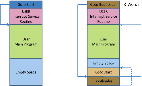
Example:
#option bootloader 0x800
#Option NoContextSave
Syntax:
#option NoContextSave
Explanation:
Interrupts can occur at almost any time, and may interrupt another command as it runs. To ensure that the interrupted command can continue properly after the interrupt, some temporary variables (the context) must be saved. Normally GCBASIC will do this automatically, but in some cases it may be necessary to prevent this. If porting some existing assembly code to GCBASIC, or creating a bootloader using GCBASIC that will call another program,
NoContextSave can be used to prevent the context saving code from being added automatically.
Be very careful using this option - it is very easy to cause random corruption of variables. If creating your own context saving code, you may need to save several variables. These are:
-
For Microchip PIC microcontrollers 12F/16F: W, STATUS, PCLATH
-
For Microchip PIC microcontrollers 12F1/16F1/18F: W, STATUS, PCLATH, PCLATU, BSR
-
For Atmel AVR microcontrollers: All 32 registers
Other variables may also need to be saved, depending on what commands are used inside the interrupt handler. Everything that is saved will also need to be restored manually when the interrupt handler finishes.
Example:
' This shows an example that could be used by a bootloader to call some application code.
' The application code must deal with context save and restore
' Suppose that application code starts at location 0x100, with interrupt vector at 0x108
'Chip model
#chip 18F2620
'Do not save context automatically
#option NoContextSave
'Main bootloader routine
Set PORTB.0 On
'Do other stuff to make this an actual bootloader and not a trivial example
'Transfer control to application code
goto 0x100
'Interrupt routine - this will be placed at the interrupt vector
Sub Interrupt
'If any interrupt occurs, jump straight to application interrupt vector
goto 0x108
End Sub
#Option NoLatch
Syntax:
#option nolatch
This option disables PORTx to LATx redirection.
Introduction:
The GCBASIC compiler will redirect all I/O pin writes from PORTx to LATx registers on 16F1/18F Microchip PIC microcontrollers.
The Microchip PIC mid-range microcontrollers use a sequence known as Read-Modify-Write (RMW) when changing an output state (1 or 0) on a pin. This can cause unexpected behavior under certain circumstances.
When your program changes the state on a specific pin, for example RB0 in PORTB, the microcontroller first READs all 8 bits of the PORTB register which represents the states of all 8 pins in PORTB (RB7-RB0).
The microcontroller then stores this data in the MCU. The bit associated with RB that you’ve commanded to MODIFY is changed, and then the microcontrollers WRITEs all 8 bits (RB7- RB0) back to the PORTB register.
During the first reading of the PORT register, you will be reading the actual state of the physical pin. The problem arises when an output pin is loaded in such a way that its logic state is affected by the load. Instances of such loads are LEDs without current-limiting resistors or loads with high capacitance or inductance.
For example, if a capacitor is attached between pin and ground, it will take a short while to charge when the pin is set to 1. On the other hand, if the capacitor is discharged, it acts like a short circuit, forcing the pin to '0' state, and, therefore, a read of the PORT register will return 0, even though we wrote a 1 to it.
GCBASIC resolves this issue using the LATx register when writing to ports, rather than using PORTx registers. Writing to a LATx register is equivalent to writing to a PORTx register, but readings from LATx registers return the data value held in the port latch, regardless of the state of the actual pin. So, for reading use PORTx.
Note:
You can use the #option nolatch if problems occur with compiler redirection.
#Option Required
Syntax:
#option REQUIRED PIC|AVR CONSTANT %message.dat entry%
#option REQUIRED PIC|AVR CONSTANT "Message string"
or
#option REQUIRED DISABLE
This option ensure that the specific CONSTANT exists within a library to ensure a specific capability is available with the microcontroller.
Introduction:
This will cause the compiler check the CONSTANT is a non zero value. If the CONSTANT does not exist it will be treated as a zero value.
Example:
This example tests the CONSTANT CHIPUSART for both the PIC and AVR microcontrollers. If the CONSTANT is zero or does not exist then the string will be displayed as an error message.
#option REQUIRED PIC CHIPUSART "Hardware Serial operations. Remove USART commands to resolve errors."
#option REQUIRED AVR CHIPUSART "Hardware Serial operations. Remove USART commands to resolve errors."
Disabling:
To disable checking capability, add the following directive.
#option REQUIRED DISABLE
#Option Shadowregister
Syntax:
#option Shadowregister GPIO|PORTA|PORTB
This option enables RMW-safe output operations for the specified port by using a shadow latch to track intended output states, preventing unintended changes to input pin states.
Introduction:
Without this option, instructions like bsf GPIO,2 on chips without LATx registers (e.g., PIC12F675) trigger a read-modify-write (RMW) operation on the port register. If any pins are configured as inputs, their bits reflect external voltage levels during the read, which can corrupt output latches when writing back. This can cause unexpected output levels, corrupted latch states during interrupts, or hard-to-trace bugs in mixed input/output setups.
When #option Shadowregister port is enabled, the compiler uses a shadow latch variable to track output states. All pin changes update the shadow latch, and writes to the port are done using full-byte transfers from the shadow latch, avoiding RMW issues.
Example:
This example enables the shadow register for GPIO on a PIC12F675, ensuring RMW-safe output for GP2 = 1.
#chip 12F675, 4
#option Shadowregister GPIO
Dir GP0 In
GP2 = 1
This compiles to RMW-safe code:
; Set GP2 high without affecting GP0
bsf LATA, 2 ; Update shadow latch
movf LATA, W
movwf GPIO ; Safe write to port#Option Volatile
Syntax:
#option volatile `bit`
This option ensure port setting are glitch-free.
Introduction:
#option volatile bit where bit is an IO bit, like PORTB.0 appended.
This will cause the compiler to set the bit without any glitches when copying a value from another variable, but will increase code size slightly.
Example:
'Set chip model
#chip 16f877a
'Example command
#option volatile portb.0
dir portb.0 out
do forever
portb.0 = !portb.0
loop
#Option ReserveHighProg
Syntax:
#option ReserveHighProg [words]
This option reserves program memory to be kept free at the top end of memory. This useful for HEF/SAF or bootloaders.
The option provided a reservation for the memory region that is normally assumed to be available to the compiler for the application code storage. In order to avoid any possible conflict (overlapping code and data usage), it is important to reserve the devices pecific memory range by using the compiler option (shown above) in the project configuration.
Using the #option ReserveHighProg [words] exposes the constant `ChipReserveHighProg in the user program.
Defined constants
The compiler has constants that can be used as an alternative to the parameter [words].
The compiler constants are: OPTIBOOT, OPTIBOOTUSB, ARDUINONANO, ARDUINOMEGA2560 or TINYBOOTLOADER.
Where these constants equate to:
OPTIBOOT = 1024
OPTIBOOTUSB = 2048
ARDUINONANO = 1024
ARDUINOMEGA2560 = 1024
TINYBOOTLOADER = 128
TINYBOOTLOADER128 = 128
TINYBOOTLOADER125 = 256
Examples 1
In the example below the region 0x1F80 to 0x1FFF (flash block for a PIC16F1509 microcontroller) has been removed from the default space available for code storage using the compiler option.
'Set chip model
#chip 16F1509
'Directive
#option ReserveHighProg 128
Examples 2
In the example below the bootloader area of Program Memory is protected.
This will ensure the program size does not overwrite the OptiBoot bootloader.
'Set chip model
#chip MEGA328P
'Directive
#option ReserveHighProg OPTIBOOT
Using Assembler
This is the Using Assembler section of the Help file. Please refer the sub-sections for details using the contents/folder view.
Assembler Overview
Introduction:
You can use microcontroller assembler code within your GCBASIC code.
You can put the assembler code inline in with your source code. The assembler code will be passed through to the assembly file associated with your project.
GCBASIC should recognise all of the commands in the microcontroller datasheet.
The commands should be in lower case, this is good practice, and have a space or tab in front of the command.
Even if the mnemonics are not being formatted properly, gputils/MPASM should still be capable of assembling the source code.
Format commands as follows:
Example:
btfsc STATUS,Z bsf PORTB,1
Macros
This is the Macros section of the Help file. Please refer the sub-sections for details using the contents/folder view.
Macros Overview
Introduction:
You can use macros within your GCBASIC code.
Macros are similar to subroutines. But during compilation, everything is inserted inline. This may increase the code size slightly, but it also reduces stack usage.
Parameters are handled in a similar way to how constants are handled, so there is a lot more freedom when passing things in to a macro. (Unlike subs or functions, where everything must be stored in a variable.)
For example, for PulseOut one parameter is a pin, and the other is a time length like "500 ms". Neither of those parameters could be stored in a variable, but passing them in as macro parameters is possible.
Demonstration Program:
'PulseOut Macro
macro Pulseout (Pin, Time)
Set Pin On
Wait Time
Set Pin Off
end macro
Example Macros
This is the Example Macros section of the Help file. Please refer the sub-sections for details using the contents/folder view.
Measuring a Pulse Width
Introduction
The demonstration shows how a macro can be used to optimised code by compiling code inline.
When the measurement of a pulse width to sub-microsecond resolution is required for instance measuring the high or low pulse width of an incoming analog signal a comparator can be combined with a timer to provide the pulse width.
Microchip PIC has published a "Compiled Tips 'N Tricks Guide" that explains how to do certain tasks with Microchip PIC 8-bit microcontrollers.
This guide provides the steps that need to be taken to perform the task of measuring a pulse width. The guide provides guidance on measuring a pulse width using Timer 1 and the CCP module. This guidance was used as the basis for the GCBASIC port the shown below. The guidance was generic and in this example polling the CCP flag bit was more convenient than using an interrupt.
In this demonstration shown below, a 16F1829 microcontroller operating at 32 Mhz uses the internal oscillator. The demonstration code is based on a macro that uses Timer1 and CCP4. However, any of the four CCP modules could be used, the 16F1829 microcontroller has four CCP module.
The timer resolution of this method uses a timer Prescaler of 1:8 and a microcontroller frequency of 32 MHz giving a pulse width resolution is 1ms. With the timer Prescaler of 1:2 and the microcontroller frequency of 32MHz the resolution is 250 ns.
The accuracy is dependent upon the accuracy of the system clock, but oscilliscope measurements have show an accuracy of +- 1us from 3us to 1000us.
In this demonstration the following was implemented
-
Using GCBASIC a macro to ensure the generated assembler is inline to ensure the timing is consistent and no sub routines are called.
-
Another microcontroller was used to generate the pulses to be measured
-
A TEK THS730A oscilliscope was used to measure/verify pulse widths
-
A 4x20 LDC module with an I2C Backpack was used to display the results. However, as an alternative, a serial output
to a terminal program to view the data could be used
This demonstration could be improved by adding code to poll the TIMER1 overflow flag. If the timer overflows, then either no pulse was detected or the pulse was longer than allowed by the prescaler/OSC settings. In this case, return a value of zero for pulse width.
Usage:
To get positive pulse width use:
PULSE_IN
PULSE_IN returns a global word variable Pulse_Width
Demonstration Program:
#Chip 16F1829, 32
#CONFIG MCLRE = OFF
'Setup Software I2C
#define I2C_MODE Master
#define I2C_DATA PORTA.2
#define I2C_CLOCK PORTC.0
#define I2C_DISABLE_INTERRUPTS ON
'Set up LCD
#define LCD_IO 10
#define LCD_WIDTH 20 ;specified lcd width for clarity only. 20 is the default width
#define LCD_SPEED FAST
#define LCD_Backlight_On_State 1
#define LCD_Backlight_Off_State 0
'Note: This example can be improved by adding code to poll the 'TIMER1 overflow flag. IF the timer overflows, then either no 'pulse was detected or the pulse was longer than allowed by the 'prescaler/OSC settings. In this case, return a value of zero 'for pulse width.
CLS
PRINT "Pulse Width Test"
DIM PULSE_WIDTH AS WORD
DIR PORTC.6 IN
'Setup timer
'Set timer1 using PS1_2 gives 250ns resolution
InitTimer1 OSC, PS1_8
wait 1 s
CLS
'MAIN PROGRAM LOOP
DO
PULSE_IN 'Call the Macro to get positive pulse width.
Locate 0,0
PRINT Pulse_Width
PRINT " "
wait 1 s
Loop
MACRO PULSE_IN 'Measure Pulse Width
'Configure CCP4 to Capture rising edge
CCP4CON = 5 'Set to 00000101
StartTimer 1
CCP4IF = 0
do while CCP4IF = 0 'Wait for rising edge
loop
TMR1H = 0: TMR1L = 0 'Clear timer to zero
CCP4IF = 0 'Clear flag
'Configure CCP4 to Capture Falling Edge
CCP4CON = 4 '00000100'
do while CCP4IF = 0 'Wait for falling edge
loop
StopTimer 1 'Stop the time
Pulse_Width = TIMER1 'Save the timer value
CCP4IF = 0 'Clear the CCP4 flag
End MACRO
Also see Macros Overview
Implementing a method with a Pin name as a parameter
Introduction
A constant such as a Pin name cannot be passed to a sub routine or a function. This is a constraint of GCBASIC.
A macro can be used to implement a method of passing a constant to reusable code section.
The example shown below implements a button press routine and takes an input port constant and prints the result on an LCD display.
Note: A macro will use more program memory as the macro will be compiled as inline code. Therefore, for every use of the macro will use additional program memory - the same amount of program memory for each call to the macro.
Demonstration Program:
#chip 16F877a, 16
#define Button PORTC.1 ' Switch on PIN 14 via 10K pullup resistor
DIR Button In
wait 1 sec
'USART settings
#define USART_BAUD_RATE 9600
#define USART_TX_BLOCKING
;======== MAIN PROGRAM LOOP ================
HSerPrint "Button Test"
HSerPrintCRLF 2
Do
Test_button ( button )
Loop
;==========================================
Macro Test_button (Button)
if Button = ON then
wait 10 ms 'debounce
ButtonCount = 0
Do While Button = On
Wait 10 ms
ButtonCount += 1
Loop
if ButtonCount > 5 then
if ButtonCount > 50 then 'Long push
hserprint "Long push"
else 'Short push
hserprint "Short push"
end if
HSerPrintCRLF
end if
wait 1 s
end if
End Macro
Also see Macros Overview
Example Programs
Flashing LEDs and an Interrupt
Explanation:
This code implements four flashing LEDs. This is based on the Microchip PIC Low Pin Count Demo Board.
The example program will blink the four red lights in succession. Press the Push Button Switch, labeled SW1, and the sequence of the lights will reverse. Rotate the potentiometer, labeled RP1, and the light sequence will blink at a different rate.
This implements an interrupt for the switch press, reads the analog port and set the LEDs.
Demonstration program:
#chip 18F14K22, 32
#config MCLRE_OFF
'Works with the low count demo board
'Set the input pin direction
#define SwitchIn1 PORTa.3
Dir SwitchIn1 In
#define LedPort PORTc
DIR PORTC OUT
'Setup the ADC pin direction
Dir PORTA.0 In
dim ADCreading as word
'Setup the input pin direction
#define IntPortA PORTA.1
Dir IntPortA In
'Variable and constants
#define intstate as byte
intstate = 0
#define minwait 1
dim ccount as byte
dim leddir as byte
ccount = 8
leddir = 0
SET PORTC = 15
WAIT 1 S
SET PORTC = 0
'Setup the Interrupt
Set IOCA.3 on
Dir porta.3 in
On Interrupt PORTABCHANGE Call Setir
'Set initial LED direction
setLedDirection
DO FOREVER
INTON
ADCreading = ReadAD10(AN0)
if ADCreading < minwait then ADCreading = minwait
'Set LEDs
Set PortC = ccount
wait ADCreading ms
if leddir = 0 then
rotate ccount left simple
'Restart LED position
if ccount = 16 then
ccount = 128
end if
end if
if leddir = 1 then
rotate ccount Right simple
'Restart LED position
if ccount = 128 then
ccount = 8
end if
end if
'Reset interrupt - this may be been reset so set to zero so interrupt can operate.
intstate = 0
Loop
'Interrupt routine.
sub Setir
if IntPortA = 0 and intstate = 0 then
intstate = 1
wait while SwitchIn1 = 0
setLedDirection
end if
end sub
sub setLedDirection
'Set LED values
select case leddir
case 0
leddir = 1
ccount = 8
case 1
leddir = 0
ccount = 1
end select
End Sub
See Also Interrupts, ReadAD10
Flashing LED with timing parameters
Explanation:
This is an example of how to define a subroutine.
When called, this subroutine will blink an LED for the number of times and duration as determined by the input parameters.
The syntax of the subroutine is:
' Flash_LED (numtimes, OnTime, (optional) OffTime)
' Where numtimes is from 1 - 255 and OnTime/OffTime is
' from 0 - 65535 ms. If OffTime is not entered, then
' OffTime = OnTime.
Sub Flash_LED (in numtimes, in OnTime as WORD, Optional OffTime as WORD = OnTime)
repeat numtimes
set LED on
wait OnTime ms
set LED OFF
wait OffTime ms
end repeat
End Sub
Shown below is a working example program using a Microchip PIC 18F25K22.
Change Settings/PORTS as needed for other Chips.
Connect an LED to the LED pin via a 1K series resistor.
Demonstration program:
#chip 18F25K22, 16
#define LED PORTC.1 'Led on PIN 14 via 1K resistor
DIR LED OUT
wait 1 sec
;======== MAIN PROGRAM LOOP ================
Do
Flash_LED ( 3,250 ) '3 Flashes 250 ms equal on/off time
Wait 2 Sec
Flash_LED ( 5,250,500 ) '5 flashes On 250 ms / off 500 ms
Wait 2 Sec
Flash_LED ( 10,100 ) '10 rapid flashes
Wait 2 Sec
Loop
;==========================================
Sub Flash_LED (in numtimes, in OnTime as WORD, optional OffTime as word = OnTime)
repeat numtimes
set LED on
wait OnTime ms
set LED OFF
wait OffTime ms
end repeat
End Sub
Generate Accurate Pulses
Explanation:
The PulseOut Command is a reliable method for generating pulses if accuracy is not critical,
the PulseOut command uses a calculation of the clock to speed for the timing .
If you need better accuracy and resolution then an alternative approach is required.
To generate pulses in the 100 us to 2500 us range with an accuracy of +- 1us over this range is practical using the approach shown in this example.
This example code works on a midrange PIC16F690 operating at 8Mhz. However, it should work on any Microchip PIC microcontroller, but may need some minor modifications.
Usage:
Pulse_Out_us ( word_value )
How It Works:
Timer1 is loaded with a preset value based upon the variable passed to the sub routine.
The timer (Timer1) is started and the pulse pin (the output pin) is set high.
When Timer1 overflows the Timer1 interrupt flag bit (TMR1IF) is set. This causes the program to
exit a polling loop and set the pulse Pin off. Then, Timer1 is stopped and TMRIF flag is cleared and the sub routine exits.
This method supports delays between 5 us and 65535 us and uses Timer1.
Test Results:
These tests were completed using a Saleae Logic Analyzer.
| Pulse setting | Time Results |
|---|---|
|
|
|
|
|
|
|
|
|
|
Demonstration program:
;**************************************
; Code: Output an accurate pulse
; Author: William Roth 03/13/2021
;**************************************
#chip 16F690,8
; ---- Define Hardware settings
; ---- Define I2C settings - CHANGE PORTS AS REQUIRED
#define I2C_MODE Master
#define I2C_DATA PORTB.4
#define I2C_CLOCK PORTB.6
#define I2C_DISABLE_INTERRUPTS ON
; ---- Set up LCD - Using I2C LCD Backpack
#define LCD_IO 10
#define LCD_WIDTH 20 ;specified lcd width for clarity only. 20 is the default width
#define LCD_I2C_Address_1 0x4e ; default to 0x4E
; ---- May need to use SLOW or MEDIUM if your LCD is a slower device.
#define LCD_SPEED Medium
#define LCD_Backlight_On_State 1
#define LCD_Backlight_Off_State 0
CLS
; ---- USART settings
#define USART_BAUD_RATE 38400
#define USART_TX_BLOCKING
DIR PORTB.7 OUT
; ---- Setup Pulse parameters
#define PulsePin PORTC.4
Dim Time_us As WORD
Dir PulsePin Out 'Pulsout pin
Set PulsePin off
; ---- Setup Timer
InitTimer1 Osc, PS1_2 'For 8Mhz Chip
'InitTimer1 Osc, PS1_4, 'For 16 Mhz Chip
TMR1H = 0: TMR1L = 0 'Clear timer1
TMR1IF = 0 'Clear timer1 int flag
TMR1IE = on 'Enable timer1 Interrupt (Flag only)
' **** This is the MAIN loop *****
Do
PULSE_OUT_US (2500) 'Measured as 2501.375 us
wait 19 ms
Pulse_Out_US (1000) 'Measured as 1000.750 us
wait 19 ms
Pulse_Out_US (100) 'Measured as 100.125 us
wait 19 ms
Pulse_Out_US (10) 'Measured as 10.125 us
Wait 19 ms
loop
SUB PULSE_OUT_US (IN Variable as WORD)
TMR1H = 65535 - Variable_H 'Timer 1 Preset High
TMR1L = (65535 - Variable) + 4 'Timer 1 Preset Low
Set TMR1ON ON 'Start timer1
Set PulsePin ON 'Set Pin high
Do While TMR1IF = 0 'Wait for Timer1 overflow
Loop
Set PulsePin off ' Pin Low
Set TMR1ON OFF ' Stop timer 1
TMR1IF = 0 'Clear the Int flag
END SUB
Also see PulseOut
Graphical LCD Demonstration
Explanation:
This demonstration code shows the set of commands supported by GCBASIC.
Demonstration program:
;Chip Settings
#chip 16F877a,16
#include <glcd.h>
'Setup the GLCD
#Define glcd_rw PORTD.3 'RW pin on LCD
#Define glcd_reset PORTD.4 'Reset pin on LCD
#Define glcd_cs1 PORTD.1 'CS1, CS2 can be reversed
#Define glcd_cs2 PORTD.2 'CS1, CS2 are be reversed
#Define glcd_rs PORTD.5 'D/I pin on LCD
#Define glcd_enable PORTD.4 'E pin on LCD
#Define glcd_db0 PORTB.0 'D0
#Define glcd_db1 PORTB.1 'D1
#Define glcd_db2 PORTB.2 'D2
#Define glcd_db3 PORTB.3 'D3
#Define glcd_db4 PORTB.4 'D4
#Define glcd_db5 PORTB.5 'D5
#Define glcd_db6 PORTB.6 'D6
#Define glcd_db7 PORTB.7 'D7 on LCD
'Specify the type of GLCD
#define GLCD_TYPE GLCD_TYPE_KS0108
#define GLCD_WIDTH 128
#define GLCD_HEIGHT 64
#define GLCD_PROTECTOVERRUN
wait 1 s
GLCDCLS
GLCDPrint 0, 1, "GCBASIC "
wait 1 s
GLCDCLS
rrun = 0
dim msg1 as string * 16
do forever
GLCDCLS
Box 18,30,28,40
Line 0,0,127,63
Line 0,63,127,0
wait 1 s
FilledBox 18,30,28,40
wait 1 s
GLCDCLS
GLCDDrawString 30,0,"ChipMhz@"
GLCDDrawString 78,0, str(ChipMhz)
Circle(10,10,10,1) 'upper left
Circle(117,10,10,1) 'upper right
Circle(63,31,10,1) 'center
Circle(63,31,20,1) 'center
Circle(10,53,10,1) 'lower left
Circle(117,53,10,1) 'lower right
wait 1 s
GLCDDrawString 30,0,"ChipMhz@"
GLCDDrawString 78,0, str(ChipMhz)
FilledCircle(10,10,10,1) 'upper left
FilledCircle(117,10,10,1) 'upper right
FilledCircle(63,31,10,1) 'center
FilledCircle(63,31,20,1) 'center
FilledCircle(10,53,10,1) 'lower left
FilledCircle(117,53,10,1) 'lower right
wait 1 s
GLCDCLS
GLCDDrawString 30,0,"ChipMhz@"
GLCDDrawString 78,0, str(ChipMhz)
Circle(10,0,10,1) 'upper left
Circle(117,0,10,1) 'upper right
Circle(63,31,10,1) 'center
Circle(63,31,20,1) 'center
Circle(10,63,10,1) 'lower left
Circle(117,63,10,1) 'lower right
wait 1 s
GLCDCLS
GLCDDrawString 0,10,"Hello" 'Print Hello
wait 1 s
GLCDDrawString 0,10, "ASCII #:" 'Print ASCII #:
Box 18,30,28,40 'Draw Box Around ASCII Character
for char = 0x30 to 0x39 'Print 0 through 9
GLCDDrawString 16, 20 , Str(char)+" "
GLCDdrawCHAR 20, 30, char
wait 250 ms
next
line 0,50,127,50 'Draw Line using line command
for xvar = 0 to 80 'Draw line using Pset command
pset xvar,63,on
next
FilledBox 18,30,28,40 'Draw Box Around ASCII Character '
wait 1 s
GLCDCLS
GLCDDrawString 0,10,"End "
wait 1 s
GLCDCLS
workingGLCDDrawChar:
dim gtext as string
gtext = "KS0108"
for xchar = 1 to gtext(0) 'Print 0 through 9
xxpos = (1+(xchar*6)-6)
GLCDDrawChar xxpos , 0 , gtext(xchar)
next
GLCDDrawString 1, 9, "GCBASIC @2021"
GLCDDrawString 1, 18,"GLCD 128*64"
GLCDDrawString 1, 27,"Using GLCD.H from GCB"
GLCDDrawString 1, 37,"Using GLCD.H GCB@2021"
GLCDDrawString 1, 45,"GLCDDrawChar method"
GLCDDrawString 1, 54,"Test Routines"
wait 1 s
GLCDCLS
msg1 = "Run = " +str(rrun)
rrun++
GLCDPrint 0, 3, msg1
wait 1 s
GLCDCLS
loop
For more help, see Graphical LCD Demonstration, GLCDCLS, GLCDDrawChar, GLCDPrint, GLCDReadByte, GLCDWriteByte, Pset
InfraRed Remote
Explanation:
GCBASIC support interfacing with IR remote controls. The header file contains explanations, for both hardware and software.
This has been tested on many different IR sensors, and different remote controls.
Demonstration program:
The example is expected to work with most any IR sensor running at a 38 kHz carrier frequency.
;This demo prints the device number and key number sent by
;a Sony compatible IR remote control unit to an LCD
;Thomas Henry --- 4/23/2014
#chip 16F88, 8 ;PIC16F88 running at 8 MHz
#config mclr=off ;reset handled internally
#include <SonyRemote.h> ;include the header file
;----- Constants
#define LCD_IO 4 ;4-bit mode
#define LCD_WIDTH 20 ;specified lcd width for clarity only. 20 is the default width
#define LCD_RS PortB.2 ;pin 8 is Register Select
#define LCD_Enable PortB.3 ;pin 9 is Enable
#define LCD_DB4 PortB.4 ;DB4 on pin 10
#define LCD_DB5 PortB.5 ;DB5 on pin 11
#define LCD_DB6 PortB.6 ;DB6 on pin 12
#define LCD_DB7 PortB.7 ;DB7 on pin 13
#define LCD_NO_RW 1 ;ground RW line on LCD
#define IR_DATA_PIN PortA.0 ;sensor on pin 17
;----- Variables
dim device, button as byte
;----- Program
dir PortA in ;A.0 is IR input
dir PortB out ;B.2 - B.6 for LCD
do
readIR_Remote(device, button) ;wait for button press
cls ;show device code
print "Device: "
print device
locate 1,0
print "Button: " ;show button code
print button
wait 10 mS ;ignore any repeats
loop ;repeat forever
See also SonyRemote.h.
SonyRemote.h
Explanation: Sony IR Remote Control Library for GCBASIC
This include file will let you easily read and use the infrared signals from a Sony compatible television remote control. In particular, the remote control transmits a pulse modulated signal, the sensor detects this, and the subroutine in this header file decodes the signal, returning two numbers: one representing the device (television, VCR, DVD, tuner, etc.), while the the other returns the key which has been depressed (VOL+, MUTE, channel numbers 0 through 9, etc.).
This has been tested and confirmed with a fixed remote control purchased surplus for $2.00 from All Electronics, as well as an universal remote control, set to Sony mode.
Moreover it has also been tested with a Panasonic IR sensor and a Vishay sensor, both purchased surplus for about fifty cents.
Every combination performed well, and it is probably the case that most any garden variety 38 kHz IR sensor will work. The only tricky bit is making sure you get the pinout for your sensor correct, search out the datasheet for whichever device you use.
There are only three pins: Ground Vcc Data
It is essential to filter the power applied to the Vcc pin. Do this by connecting a 100 ohm resistor from the +5V power supply to the Vcc pin, and bridge the pin to ground with a 4.7uF electrolytic capacitor.
The Data pin requires a 4.7k pullup resistor.
There is only one constant required of the calling program. It indicates which port line the IR sensor is connected to. For example,
#DEFINE IR_DATA_PIN PORTA.0
There is one subroutine:
readIR_Remote(IR_rem_dev, IR_rem_key)
The values returned are, respectively, the device number mentioned earlier and the key that is currently pressed. Both are byte values.
Seventeen local bytes are consumed, and two bytes are used for the output parameters. That’s a grand total of nineteen bytes required when invoking this subroutine.
Header File
sub readIR_Remote(out IR_rem_dev as byte, out IR_rem_key as byte)
dim IR_rem_count, IR_rem_i as byte
dim IR_rem_width(12) as byte ;pulse width array
do
IR_rem_count = 0 ;wait for start bit
do while IR_DATA_PIN = 0 ;measure width (active low)
wait 100 uS ;24 X 100 uS = 2.4 mS
IR_rem_count++
loop
loop while IR_rem_count < 20 ;less than this so wait
for IR_rem_i = 1 to 12 ;read/store the 12 pulses
do
IR_rem_count = 0
do while IR_DATA_PIN = 0 ;zero = 6 units = 0.6 mS
wait 100 uS ;one = 12 units = 1.2 mS
IR_rem_count++
loop
loop while IR_rem_count < 4 ;too small to be legit
IR_rem_width(IR_rem_i) = IR_rem_count ;else store pulse width
next IR_rem_i
IR_rem_key = 0 ;command built up here
for IR_rem_i = 1 to 7 ;1st 7 bits are the key
IR_rem_key = IR_rem_key / 2 ;shift into place
if IR_rem_width(IR_rem_i) > 10 then ;longer than 10 mS
IR_rem_key = IR_rem_key + 64 ;so call it a one
end if
next
IR_rem_dev = 0 ;device number built up here
for IR_rem_i = 8 to 12 ;next 5 bits are device number
IR_rem_dev = IR_rem_dev / 2
if IR_rem_width( IR_rem_i ) > 10 then
IR_rem_dev = IR_rem_dev + 16
end if
next
end sub
Midpoint Circle Algorithm
Explanation:
GCBASIC can draw circles using the midpoint circle algorithm. The midpoint circle algorithm determines the points needed for drawing a circle. The algorithm is a variant of Bresenham’s line algorithm, and is thus sometimes known as Bresenham’s circle algorithm, although not actually invented by Jack E. Bresenham.
The example program below show the midpoint circle algorithm within GCBASIC.
Example Output on GLCD Device:
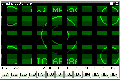
'Midpoint Circle algorithm
'Chip model
#chip 16F886, 8 ;PIC16F88 running at 8 MHz
#config mclr=off ;reset handled internally
#include <glcd.h>
;----- Constants
;Pinout is shown for the LCM12864H-FSB-FBW
;graphical LCD available from Amazon.
; +5V ;LCD pin 1
; ground ;LCD pin 2
; Vo = wiper of pot ;LCD pin 3
#define GLCD_DB0 PORTB.0 ;LCD pin 4
#define GLCD_DB1 PORTB.1 ;LCD pin 5
#define GLCD_DB2 PORTB.2 ;LCD pin 6
#define GLCD_DB3 PORTB.3 ;LCD pin 7
#define GLCD_DB4 PORTB.4 ;LCD pin 8
#define GLCD_DB5 PORTB.5 ;LCD pin 9
#define GLCD_DB6 PORTB.6 ;LCD pin 10
#define GLCD_DB7 PORTB.7 ;LCD pin 11
#define GLCD_CS2 PORTA.0 ;LCD pin 12
#define GLCD_CS1 PORTA.1 ;LCD pin 13
#define GLCD_RESET PORTA.2 ;LCD pin 14
#define GLCD_RW PORTA.3 ;LCD pin 15
#define GLCD_RS PORTA.4 ;LCD pin 16
#define GLCD_ENABLE PORTA.6 ;LCD pin 17
; Vee = pot low side ;LCD pin 18
; backlight anode ;LCD pin 19
; backlight cathode ;LCD pin 20
#define GLCD_TYPE GLCD_TYPE_KS0108
#define GLCD_WIDTH 128
#define GLCD_HEIGHT 64
;----- Program
Do forever
GLCDDrawString 30,0,"ChipMhz@"
GLCDDrawString 78,0, str(ChipMhz)
Circle(10,10,10,0) ;upper left
Circle(117,10,10,0) ;upper right
Circle(63,31,10,0) ;center
Circle(63,31,20,0) ;center
Circle(10,53,10,0) ;lower left
Circle(117,53,10,0) ;lower right
GLCDDrawString 30,54,"PIC16F886"
loop
I2C Master Hardware
Explanation:
This program demonstrates how to read and write data from an EEPROM device using the serial protocal called I2C.
This program uses the hardware I2C module within the microcontroller. If your microcontroller does not have a hardware I2C module then please use the software I2C GCBASIC ibrary.
This program has three sections.
-
Read a single byte from the EEPROM
-
Write and read a page of 64 bytes to and from the EEPROM, and
-
Finally display the contents of the EEPROM.
This program has an interrupt driven serial handler to capture and manage input from a serial terminal.
Demonstration program:
'Change the microcontroller, frequency and config to suit your needs.
#chip 16F1937, 32
#config MCLRE_ON
'Required Library to read and write to an EEPROM
#include <I2CEEPROM.h>
' Define I2C settings - CHANGE PORTS
#define HI2C_BAUD_RATE 400
#define HI2C_DATA PORTC.4
#define HI2C_CLOCK PORTC.3
'I2C pins need to be input for SSP module for Microchip PIC devices.
Dir HI2C_DATA in
Dir HI2C_CLOCK in
'I2C MASTER MODE
HI2CMode Master
' THIS CONFIG OF THE SERIAL PORT WORKS WITH max232 THEN TO PC
' USART settings
#define USART_BAUD_RATE 9600
Dir PORTc.6 Out
Dir PORTc.7 In
#define USART_DELAY OFF
#define USART_TX_BLOCKING
wait 500 ms
'Create a Serial Interrupt Handler
On Interrupt UsartRX1Ready Call readUSART
' Constants etc required for the serial Buffer Ring
#define BUFFER_SIZE 32
#define bkbhit (next_in <> next_out)
' Required Variables for the serial Buffer Ring
Dim buffer(BUFFER_SIZE)
Dim next_in as byte: next_in = 1
Dim next_out as byte: next_out = 1
Dim syncbyte as Byte
wait 125 ms
' Read ONE byte from the EEPROM
dim DeviceID as byte
dim EepromAddress, syscounter as word
#define EEpromDevice 0xA0
'Master Main Loop
location = 0
'Define our array
dim outarray(64), inarray(64)
do
HSerPrintCRLF 2
HSerPrint "Commence Array Write and Read"
'Populate the array
for tt = 1 to 64
outarray(tt) = tt
next
'Library write call is: eeprom_wr_array(device_number, page_size, address, array_name, number_of_bytes)
eeprom_wr_array(EEpromDevice, 64, location, outarray, 64)
'Library read call is: eeprom_rd_array(device_number, address, array_name, number_of_bytes)
eeprom_rd_array(EEpromDevice, location, inarray, 64)
'Show results of the read of the I2C EEPROM
HSerPrintCRLF 2
for tt = 1 to 64
if outarray(tt) <> inarray(tt) then
Hserprint "!"
HSerPrint inarray(tt)
else
HSerPrint inarray(tt)
end if
HSerPrint ","
next
HSerPrintCRLF 2
HSerPrint "Commence Write and Read a single byte":HSerPrintCRLF
HSerPrint "Read value should be "
HSerPrint str(location):HSerPrintCRLF
HSerPrint "Read = "
'Use library to write and read from the I2C EEPROM
eeprom_wr_byte (EEpromDevice, location, location)
eeprom_rd_byte (EEpromDevice, location, bbyte )
HSerPrint bbyte
location++
HSerPrintCRLF 2
'Show the connnected I2C devices on the Serial terminal.
HI2CDeviceSearch
HSerPrint "Commence Dump of the EEPROM"
validateEEPROM
Loop
End
'Show the attached I2C devices
sub HI2CDeviceSearch
'Assumes serial is operational
HSerPrintCRLF
HSerPrint "I2C Device Search"
HSerPrintCRLF 2
for deviceID = 0 to 255
HI2CStart
HI2CSend ( deviceID )
if HI2CAckPollState = false then
HSerPrint "ID: 0x"
HSerPrint hex(deviceID)
HSerSend 9
testid = deviceID | 1
select case testid
case 49
Hserprint "DS2482_1Channel_1Wire Master"
case 65
Hserprint "Serial_Expander_Device"
Case 73
Hserprint "Serial_Expander_Device"
case 161
Hserprint "EEProm_Device_Device"
case 163
Hserprint "EEProm_Device_Device"
case 165
Hserprint "EEProm_Device_Device"
case 167
Hserprint "EEProm_Device_Device"
case 169
Hserprint "EEProm_Device_Device"
case 171
Hserprint "EEProm_Device_Device"
case 173
Hserprint "EEProm_Device_Device"
case 175
Hserprint "EEProm_Device_Device"
case 209
Hserprint "DS1307_RTC_Device"
case 249
Hserprint "FRAM_Device"
case else
Hserprint "Unknown_Device"
end select
HI2CSend ( 0 )
HSerPrintCRLF
end if
HI2CStop
next
HSerPrint "End of Device Search"
HSerPrintCRLF 2
end sub
'Validation EEPROOM code
sub validateEEPROM
EepromAddress = 0
HSerPrintCRLF 2
HSerPrint "Hx"
HSerPrint hex(EepromAddress_h)
HSerPrint hex(EepromAddress)
HSerPrint " "
for EepromAddress = 0 to 0xffff
'Read from EEPROM using a library function
eeprom_rd_byte EEPromDevice, EepromAddress, objType
HSerPrint hex(objType)+" "
if ((EepromAddress+1) % 8 ) = 0 then
HSerPrintCRLF
HSerPrint "Hx"
syscounter = EepromAddress + 1
HSerPrint hex(syscounter_h)
HSerPrint hex(syscounter)
HSerPrint " "
end if
'Has serial data been received
if bkbhit then
syschar = bgetc
select case syschar
case 32
do while bgetc = 32
loop
case else
HSerPrintCRLF
HSerPrint "Done"
exit sub
end select
end if
next
HSerPrintCRLF
HSerPrint "Done"
end Sub
' Start of Serial Support functions
' Required to read the serial port
' Assumes serial port has been initialised
Sub readUSART
buffer(next_in) = HSerReceive
temppnt = next_in
next_in = ( next_in + 1 ) % BUFFER_SIZE
if ( next_in = next_out ) then ' buffer is full!!
next_in = temppnt
end if
End Sub
' Serial Support functions
' Get characters from the serial port
function bgetc
wait while !(bkbhit)
bgetc = buffer(next_out)
next_out=(next_out+1) % BUFFER_SIZE
end Function
I2C Slave Hardware
Explanation:
This program demonstrates how to control and display using a LCD the code for the keypad.
This program can be adapted. This program uses the hardware I2C module within the microcontroller. If your microcontroller does not have a hardware I2C module then please use the software I2C GCBASIC library for most microcontrollers.
This program also has an interrupt driven I2C handler to manage the I2C from the Start event.
Demonstration program:
'Code for the keypad and LCD Microchip PIC microcontroller on the Microlab board v2
'microcontroller is responsible for:
' - Reading keypad
' - Displaying data on LCD
' - communication with main Microchip PIC microcontroller via I2C
' - providing 5 keypad lines to main Microchip PIC microcontroller (for compatibility)
' - receiving remote control signals for button and keypad
'This code has support for two keypad layouts. This is one possible layout:
'0123
'4567
'89AB
'CDEF
'And this is the other possible layout:
'123A
'456E
'789D
'A0BC
'Select the keypad layout by uncommenting one of these lines:
'#define KEYPAD_KEYMAP KeypadMap0123
#define KEYPAD_KEYMAP KeypadMap123F
'Chip and config
#chip 16F882, 8
'Ports connected to keypad
'Column ports need pullups, hence columns are on PORTB for built in weak pullups
#define KEYPAD_COL_1 PORTB.4
#define KEYPAD_COL_2 PORTB.5
#define KEYPAD_COL_3 PORTB.6
#define KEYPAD_COL_4 PORTB.7
#define KEYPAD_ROW_1 PORTA.4
#define KEYPAD_ROW_2 PORTA.3
#define KEYPAD_ROW_3 PORTA.2
#define KEYPAD_ROW_4 PORTA.1
'Ports connected to LCD
#define LCD_IO 4
#define LCD_WIDTH 20 ;specified lcd width for clarity only. 20 is the default width
#define LCD_RW PORTA.7
#define LCD_RS PORTA.6
#define LCD_Enable PORTA.5
#define LCD_DB4 PORTA.4
#define LCD_DB5 PORTA.3
#define LCD_DB6 PORTA.2
#define LCD_DB7 PORTA.1
#define BACKLIGHT PORTA.0
'Button port (for remote control)
#define BUTTON PORTB.0
'Keypad ports connected to main Microchip PIC microcontroller
'These are disabled when KeyoutDisabled = true
#define KEYOUT_A PORTC.5
#define KEYOUT_B PORTC.2
#define KEYOUT_C PORTC.1
#define KEYOUT_D PORTC.0
#define KEYOUT_DA PORTB.1
'I2C ports
#define I2C_DATA PORTC.4
#define I2C_CLOCK PORTC.3
'RS232/USART settings
'To do if/when remote support needed
'Initialise
Dir KEYOUT_A Out
Dir KEYOUT_B Out
Dir KEYOUT_C Out
Dir KEYOUT_D Out
Dir KEYOUT_DA Out
Dir BACKLIGHT Out
Dir BUTTON In 'Is an output, turn off by switching pin to Hi-Z
'Initialise I2C Slave
'I2C pins need to be input for SSP module
Dir I2C_DATA In
Dir I2C_CLOCK In
HI2CMode Slave
HI2CSetAddress 128
'Buffer for incoming I2C messages
'Each message takes 4 bytes
Dim I2CBuffer(10)
BufferSize = 0
OldBufferSize = 0
'Set up interrupt to process I2C
On Interrupt SSP1Ready Call I2CHandler
'Enable weak pullups on B4-7 (keypad col pins)
NOT_RBPU = 0
WPUB = b'11110000'
'Key buffers
'255 indicates no key, other value gives currently pressed key
RemoteKey = 255
OutKey = 255
KeyoutDisabled = False 'False if KEYOUT lines used to send key
'Main loop
Do
'Read keypad, send value
CheckPressedKeys
SendKeys
'Check for I2C messages
ProcessI2C
Loop
'This keymap table is for this arrangement:
'0123
'4567
'89AB
'CDEF
Table KeypadMap0123
3
7
11
15
2
6
10
14
1
5
9
13
0
4
8
12
End Table
'This keymap table is for this arrangement:
'123F
'456E
'789D
'A0BC
Table KeypadMap123F
15
14
13
12
3
6
9
11
2
5
8
0
1
4
7
10
End Table
Sub CheckPressedKeys
'Subroutine to:
' - Read keypad
' - Check remote keypress
' - Decide which key to output
'Read keypad
If RemoteKey <> 255 Then
OutKey = RemoteKey
Else
EnableKeypad
OutKey = KeypadData
End If
End Sub
Sub EnableKeypad
'Disable LCD so that keypad can be activated
Set LCD_RW Off 'Write mode, don't let LCD write
'Re-init keypad
InitKeypad
End Sub
Sub I2CHandler
'Handle I2C interrupt
'SSPIF doesn't trigger for stop condition, only start!
'If buffer full flag set, read
Do While HI2CHasData
HI2CReceive DataIn
'Sending code
If BufferSize = 0 Then
LastI2CWasRead = False
'Detect read address
If DataIn = 129 Then
LastI2CWasRead = True
HI2CSend OutKey
KeyoutDisabled = True
Dir KEYOUT_A In
Dir KEYOUT_B In
Dir KEYOUT_C In
Dir KEYOUT_D In
Dir KEYOUT_DA In
Exit Sub
End If
End If
If BufferSize < 10 Then I2CBuffer(BufferSize) = DataIn
BufferSize += 1
Loop
End Sub
Sub SendKeys
'Don't run if not using KEYOUT lines
If KeyoutDisabled Then Exit Sub
'Send pressed keys
If OutKey <> 255 Then
'If there is a key pressed, set output lines
If OutKey.0 Then
KEYOUT_A = 1
Else
KEYOUT_A = 0
End If
If OutKey.1 Then
KEYOUT_B = 1
Else
KEYOUT_B = 0
End If
If OutKey.2 Then
KEYOUT_C = 1
Else
KEYOUT_C = 0
End If
If OutKey.3 Then
KEYOUT_D = 1
Else
KEYOUT_D = 0
End If
KEYOUT_DA = 1
Else
'If no key pressed, clear data available line to main Microchip PIC microcontroller
KEYOUT_DA = 0
End If
End Sub
Sub ProcessI2C
If HI2CStopped Then
IntOff
If LastI2CWasRead Then BufferSize = 0
If BufferSize <> 0 Then
OldBufferSize = BufferSize
BufferSize = 0
End If
IntOn
End If
If OldBufferSize <> 0 Then
CmdControl = I2CBuffer(1)
'Set backlight
If CmdControl.6 = On Then
Set BACKLIGHT On
Else
Set BACKLIGHT Off
End If
'Set R/S bit
LCD_RS = CmdControl.4
'Send bytes to LCD
LCDDataBytes = CmdControl And 0x0F
If LCDDataBytes > 0 Then
For CurrSendByte = 1 To LCDDataBytes
LCDWriteByte I2CBuffer(LCDDataBytes + 1)
Next
End If
'LCDWriteByte I2CBuffer(2)
OldBufferSize = 0
End If
End Sub
RGB LED Control
Explanation:
This program demonstrates how to drive an RGB LED to create 4096 different colors. Each of the three elements (red, green and blue) responds to 16 different levels. A value of 0 means the element never turns on, while a value of 15 means the element never shuts off. Values in between these two extremes vary the pulse width.
This program is an interrupt driven three channel PWM implementation.
The basic carrier frequency depends upon the microcontroller clock speed. For example, with an 8 MHz clock, the LED elements are modulated at about 260 Hz. The interrupts are generated by Timer 0. With an 8 MHz clock they occur about every 256 uS. The interrupt routine consumes about 20 uS.
Do not forget the current limiting resistors to the LED elements. A value of around 470 ohms is typical, but you may want to adjust the individual values, to balance the color response.
In this demonstration, three potentiometers are used to set the color levels using the slalom technique.
Demonstration program:
;----- Configuration
#chip 16F88, 8 ;PIC16F88 running at 8 MHz
#config mclr=off ;reset handled internally
;----- Constants
#define LED_R PortB.0 ;pin to red element
#define LED_G PortB.1 ;pin to green element
#define LED_B PortB.2 ;pin to blue element
;----- Variables
dim redValue, greenValue, blueValue, ticks as byte
;----- Program
dir PortA in ;three pots for inputs
dir PortB out ;the LED outputs
on interrupt Timer0Overflow call update
initTimer0 Osc, PS0_1/2
do
redValue = readAD(AN0)/16 ;red -- 0 to 15
greenValue = readAD(AN1)/16 ;green -- 0 to 15
blueValue = readAD(AN2)/16 ;blue -- 0 to 15
loop
Sub update ;interrupt routine
ticks++ ;increment master timekeeper
if ticks = 15 then ;start of the count
ticks = 0
if redValue <> 0 then ;only turn on if nonzero
set LED_R on
end if
if greenValue <> 0 then
set LED_G on
end if
if blueValue <> 0 then
set LED_B on
end if
end if
if ticks = redValue then ;time to turn off red?
set LED_R off
end if
if ticks = greenValue then ;time to turn off green?
set LED_G off
end if
if ticks = blueValue then ;time to turn off blue?
set LED_B off
end if
end sub
Serial/RS232 Buffer Ring
Explanation:
This program demonstrates how to create a serial input buffer ring.
The program receives a character into the buffer and sends back. Try sending large volumes of characters…..
This program program uses an interrupt event to capture the incoming byte value and place in the buffer ring. When a byte is received the buffer ring is incremented to ensuer the next byte is handled correctly.
Testing bkbhit will set to True when a byte has been received. Reading the function bgetc will return the last byte received.
Demonstration program:
This demonstration program will support up to 256 bytes. For a larger buffer change the variables to words.
#chip 16F1937
// #chip mega4809
// #chip mega328p, 16
// Add PPS if appropiate for your chip
// [change to your config] This is the config for a serial terminal
// assumes USART1 ( or USART0 on AVRDx ), if you select USART1/2/3/4 then you MUST add the comport parameter to all HSerxxxxx functions.
// turn on the RS232 and terminal port.
// Define the USART settings
#DEFINE USART_BAUD_RATE 9600
// This assumes you are using an ANSI compatible terminal. Use PUTTY.EXE it is very easy to use.
// Main program
// Wait for terminal to settle
wait 3 s
// Create the supporting variables
Dim next_in As Byte
Dim next_out As Byte
Dim syncbyte As Byte
Dim temppnt As Byte
// Constants etc required for Buffer Ring
#DEFINE BUFFER_SIZE 8
#DEFINE bkbhit (next_in <> next_out)
// Define the Buffer
Dim buffer( BUFFER_SIZE - 1 ) // we will use element 0 in the array as part of out buffer
// Call init the buffer
InitBufferRing
HSerSend 10
HSerSend 13
HSerSend 10
HSerSend 13
HSerPrint "Started: Serial between two devices"
HSerSend 10
HSerSend 13
// Get character(s) and send back
// Get character(s) and send back
Do
// Do we have data in the buffer?
if bkbhit then
// Send the next character in the buffer to the terminal, exposed via the function `bgetc` back the terminal
HSerSend bgetc
end if
Loop
// Supporting subroutines
Sub readUSART
buffer(next_in) = HSerReceive
temppnt = next_in
next_in = ( next_in + 1 ) % BUFFER_SIZE
If ( next_in = next_out ) Then // buffer is full!!
next_in = temppnt
End If
End Sub
Function bgetc
Dim local_next_out as Byte // maintain a local copy of the next_out variable to ensure it does not change when an Interrupt happens
local_next_out = next_out
bgetc = buffer(local_next_out)
local_next_out=(local_next_out+1) % BUFFER_SIZE
INTOFF
next_out = local_next_out
INTON
End Function
Sub InitBufferRing
// Set the buffer to the first address
next_in = 0
next_out = 0
// Interrupt Handler - some have RCIE and some have U1RXIE, so handle
//
// You would need to change the Interrupt if you use USART1,2,3, or 4
//
#IFDEF BIT( RCIE )
On Interrupt UsartRX1Ready Call readUSART
#ENDIF
#IFDEF BIT( U1RXIE )
On Interrupt UART1ReceiveInterrupt Call readUSART
#ENDIF
#IFDEF AVR
#IFNDEF CHIPAVRDX
//~ Support for legacy AVR
On Interrupt UsartRX1Ready Call readUSART
#ELSE
//~ Support for AVRDx - AVRDx chips are USART0,USART1,USART2,USART3 and USART4 not USART.
On Interrupt Usart0RXReady Call readUSART
#ENDIF
#ENDIF
End Sub
Trigonometry Circle
Explanation:
GCBASIC can draw circles on a Graphical LCD device using GCBASIC library functions.
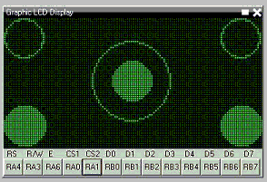
Demonstration program:
;Circle and filled circle commands on a graphic LCD.
;This uses the 2-place trigonometric routines found in the include file.
;----- Configuration
#CHIP 16F88, 8 ;PIC16F88 RUNNING AT 8 MHZ
#CONFIG MCLR=OFF ;RESET HANDLED INTERNALLY
#OPTION EXPLICIT
#DEFINE USELEGACYFORNEXT ;WILL ENSURE THE OLD FOR-NEXT Loop is used just to save some memory as this is a very simple FOR-NEXT loop
#INCLUDE <GLCD.H>
#INCLUDE <TRIG2PLACES.H>
;----- Constants
;Pinout is shown for the LCM12864H-FSB-FBW
;graphical LCD available from Amazon.
; +5V ;LCD pin 1
; ground ;LCD pin 2
; Vo = wiper of pot ;LCD pin 3
#define GLCD_DB0 PORTB.0 ;LCD pin 4
#define GLCD_DB1 PORTB.1 ;LCD pin 5
#define GLCD_DB2 PORTB.2 ;LCD pin 6
#define GLCD_DB3 PORTB.3 ;LCD pin 7
#define GLCD_DB4 PORTB.4 ;LCD pin 8
#define GLCD_DB5 PORTB.5 ;LCD pin 9
#define GLCD_DB6 PORTB.6 ;LCD pin 10
#define GLCD_DB7 PORTB.7 ;LCD pin 11
#define GLCD_CS2 PORTA.0 ;LCD pin 12
#define GLCD_CS1 PORTA.1 ;LCD pin 13
#define GLCD_RESET PORTA.2 ;LCD pin 14
#define GLCD_RW PORTA.3 ;LCD pin 15
#define GLCD_RS PORTA.4 ;LCD pin 16
#define GLCD_ENABLE PORTA.6 ;LCD pin 17
; Vee = pot low side ;LCD pin 18
; backlight anode ;LCD pin 19
; backlight cathode ;LCD pin 20
#define GLCD_TYPE GLCD_TYPE_KS0108
#define GLCD_WIDTH 128
#define GLCD_HEIGHT 64
;----- Variables
dim cx, cy, edge, jj as byte
dim ii as word
;----- Program
myCircle(10,10,10)
;upper left
myCircle(117,10,10) ;upper right
myCircleFilled(63,31,10) ;center
myCircle(63,31,20) ;center
myCircleFilled(10,53,10) ;lower left
myCircleFilled(117,53,10) ;lower right
;----- Subroutines
sub myCircle(cenX, cenY, rad)
;Center of circle = (cenX,cenY), radius = rad
for ii = 0 to 358 step 2 ;every two degrees
cx = cenX -((10*rad*cos(ii))/100+5)/10 ;properly rounded x value
cy = cenY -((10*rad*sin(ii))/100+5)/10 ;properly rounded y value
;the following ignores the pixel if off the screen
if (cx>=0 and cx<=GLCD_WIDTH and cy>=0 and cy<=GLCD_HEIGHT) then
Pset(cx, cy, on)
end if
next ii
end sub
sub myCircleFilled(cenX, cenY, rad)
;Center of circle = (cenX,cenY), radius = rad
for ii = 0 to 358 step 2
cx = cenX -((10*rad*cos(ii))/100+5)/10
cy = cenY -((10*rad*sin(ii))/100+5)/10
edge = 2 * cenX - cx ;compute right edge
for jj = cx to edge ;fill entire line, uses legacy for next permitting CX to be less than edge
if (jj>=0 and jj<=GLCD_WIDTH and cy>=0 and cy<=GLCD_HEIGHT) then
Pset(jj,cy,on)
end if
next jj
next ii
end sub
See also Trigonometry, Circle, FilledCircle,
Graphical GCBASIC
This is the Graphical GCBASIC section of the Help file. Please refer the sub-sections for details using the contents/folder view.
Code Documentation
Documenting GCBASIC is key for ease of use. This section is intended for developers only.
Documenting is the ability to read some extra information from comments in libraries.
Some comments that start with ''' have a special meaning, and will be displayed as tooltips or as information to the user. These tooltips helps inexperienced users to use extra libraries.
-
GCBASIC uses ; (a semicolon) to show comments that it has placed automatically, and // or ' to indicate ones that the user has placed. When loading a program, it will not load any that start with a ; (semi-colon). The use of comments do not impact the users but it worthy of note.
-
As for code documentation comments, GCBASIC will load information about subroutines/functions and any hardware settings that need to be set.
-
For subroutines, a line before the Sub or Function line that starts with ''' will be used as a tooltip when the user hovers over the icon. A line that starts with '''@ will be interpreted differently, depending on what comes after the @. '''@param ParamName Parameter Description will add a description for the parameter. For a subroutine, this will show in the Icon Settings panel under the parameter when the user has selected that icon.
-
For functions, it will show at the appropriate time in the Parameter Editor wizard. '''@return Returned value applies to functions only. It will be displayed in the Parameter Editor wizard when the user is asked to choose a function. An example of all this is given in srf04.h:
'''Read the distance to the nearest object
'''@param US_Sensor Sensor to read (1 to 4)
'''@return Distance in cm
Function USDistance(US_Sensor) As Word
-
If a subroutine or command is used internally in the library, but GCBASIC users should not see it, it can be hidden by placing '''@hide before the Sub or Function line. Another example from srf04.h:
'''@hide
Sub InitUSSensor
These should hopefully be pretty easy to add. It is also possible to add Hardware Settings. A particular setting can be defined anywhere in the file, using this syntax:
'''@hardware condition, display name, constant, value type
These comments informs GCBASIC when to show the setting. Normally, this is All, but sometimes it can include a constant, a space and then a comma separated list of values. display name is a friendly name for the setting to display. constant is the constant that must be set, and valuetype is the type that will be accepted for that constant’s value. To allow for multiple value types, enter a list of types with a | between them.
-
Allowed types are:
free - Allows anything
label - Allows any label
condition - Allows a condition
table - Allows a data table
bit - Allows any bit from variable, or bit variable
io_pin - Allows an IO pin
io_port - Allows an entire IO port
number - Allows any fixed number or variable
rangex:y - Allows any number between x and y
var - Allows any variable
var_byte - Allows any byte variable
var_word - Allows any word variable
var_integer - Allows any integer variable
var_string - Allows any string variable
const - Allows any fixed number
const_byte - Allows any byte sized fixed number
const_word - Allows any word sized fixed number
const_integer - Allows any integer sized fixed number
const_string - Allows any fixed string
byte - Allows any byte (fixed number or variable)
word - Allows any word
integer - Allows any integer
string - Allows any string
array - Allows any array
-
When the library is added the program, GCBASIC will show a new device with the name of the library file on the Hardware Settings window. The user can then set the relevant constants without necessarily needing to see any code. Adding a GCBASIC library to GCBASIC will not result in any changes to the library. GCBASIC uses the information it reads to help edit the user’s program, but then the user’s program is passed to the compiler along with the unchanged library.
-
Hardware Settings are a bit more involved to add, but hopefully the bit of extra documentation for subroutines will be straight forward.
Windows .NET Support
From Graphical GCBASIC version 0.941 supports use on newer Windows versions without having the pre-requisite of .NET 3.5.
GCBASIC for Linux
This is the GCBASIC for Linux section of the Help file. Please refer the sub-sections for details using the contents/folder view.
Overview - Linux Operating System
Introduction: GCBASIC can be used when using the Linux Operating System.
This instructions are not distribution specific, but are for Linux only (not Windows).
Instructions: Complete the following steps to compile and install GCBASIC for Linux:
-
Install FreeBasic from your distributions repository or http://www.freebasic.net/wiki/CompilerInstalling
-
Download the "GCBASIC - Linux Distribution" from SourceForge at https://sourceforge.net/projects/gcbasic/files/
-
Unrar/unpack GCBASIC.rar to a location of your choice within your home directory (eg. within Downloads) with either a file manager or from a console.
-
From a console, change to the GCBASIC Sources in the unpacked directory:
eg. cd ~/Downloads/sources/linuxbuild/
-
Make sure that
install.shis set as executable (ie.chmod +x install.sh), and then execute: ./install.sh build -
You will need root privileges for this step. You can switch user (su) to root, or optionally use
sudo.
Execute: [sudo] ./install.sh install
-
If you su’d to root, use
exitto drop back to your normal user. Then, be sure to follow the instructions given by the script for updating your path. -
Confirm proper execution, and the version, of GCBASIC by executing: gcbasic /version
Now you can create and compile GCBASIC source files.
Programming microcontrollers:
To program your microcontroller with your GCBASIC created hex file, you will need additional programming and programmer software.
For Microchip PIC microcontroller programming, you might find what you need at: www.pickitplus.co.uk The PICKitPlus Team provide programmers and Linux software.
For Atmel AVR microcontroller programming, you will need avrdude. It should be available in your distributions repository. If not, check here: http://www.nongnu.org/avrdude/
Make ASM, Make HEX and Programming Operations using the provided Linux scripts
The scripts provided are intended to assist in the creation of the ASM file ( from a GCBASIC source file ), creation of the HEX file ( also from a GCBASIC source file ) and to support programming operations ( often called `FLASH`ing the microcontroller ).
| Script | Usage | Example |
|---|---|---|
|
To compile the GCBASIC source program to create the ASM. |
|
|
To compile and asseble the GCBASIC source program to create the ASM and a microcontroller specific HEX file. |
|
|
To compile,asseble the GCBASIC source program to create the ASM and a microcontroller specific HEX file, and, then to program the microcontroller |
|
Examples
There are multiple constructs to run multiple programs on a single command line. The most common are ';' and '&&'
To run another command immadiately after running makehex.sh. Use the following:
makehex.sh sourcefile.gcb; anothercommand
To run another command only if makehex.sh does not exit with an error such as a compiler error. Use the following:
makehex.sh sourcefile.gcb && anothercommand
GCBASIC for ARM & Pi
This is the GCBASIC for Pi section of the Help file. Please refer the sub-sections for details using the contents/folder view.
Overview - Raspberry Pi
Introduction:
GCBASIC can be used when using the Raspberry Pi.
You can install the command-line version of GCBASIC on a Raspberry Pi (and similar single-board computers) and use it to compile your GCBASIC programs.
You can also program most PICs and AVRs using only the Pi’s GPIO pins (see [Programming]), as well as communicate with your device over the Pi’s serial port. This makes it easy to program, modify, and communicate with a PIC or AVR using just a Pi and an SSH connection.
GCBASIC is not published for ARM-based computers, there is currently no pre-compiled version for ARM-based computers, so you will have to compile it from source. The GCBASIC compiler is written in FreeBASIC (an open-source version of BASIC), so you will need to first install the FreeBASIC compiler on your Pi, then use it to compile the GCBASIC compiler from its source code. This is relatively simple.
FreeBASIC is not included in any of the major Linux repositories, but there is a customized version for ARMv7 boards like the Raspberry Pi on their web site.
The following procedure will work with any ARMv7 single-board computer running a Debian derivative like Raspberry Pi OS or Armbian. This includes the Raspberry Pi 2 and 3, and all single board computers with an Allwinner H2+ or H3 microprocessor (Orange Pi PC, Orange Pi Zero, Nano Pi R1, etc). It has not been tested with a Raspberry Pi 4.
Instructions:
All commands should be performed on your Pi board, either through a remote SSH terminal or using a keyboard and monitor connected to your Pi.
Installing FreeBASIC
-
Install FreeBASIC dependencies
$ sudo apt-get install libx11-dev libxext-dev libxpm-dev libxrandr-dev libncurses5 libncurses5-dev
-
Download the latest version FreeBASIC for ARMv7 from https://users.freebasic-portal.de/stw/builds/linux-armv7a-hf-debian/ :
$ cd ~
$ wget https://users.freebasic-portal.de/stw/builds/linux-armv7a-hf-debian/fbc_linux_armv7a_hf_debian_0376_2020-09-17.zip
$ unzip fbc_linux_armv7a_hf_debian_0376_2020-09-17.zip
-
Install FreeBASIC
$ cd fbc_linux_armv7a_hf_debian/ $ chmod +x install.sh $ sudo ./install.sh -i
Installing GCBASIC
-
Download and extract the GCBASIC sources:
$ wget "https://downloads.sourceforge.net/project/gcbasic/GCBasic%20-%20Linux%20Distribution/GCB%40Syn.rar"
$ sudo apt install unar
# the password when requested in the next step is "GCB"
$ unar GCBASIC.rar
$ cd GCBASIC/sources/linuxbuild/
-
Build and install the compiler:
$ chmod +x install.sh
$ ./install.sh build
$ sudo ./install.sh install
-
Verify the compiler is properly installed and view the full list of compiler options
$ gcbasic
Now you can create and compile GCBASIC source files. For example, to compile a program you created named myprogram.bas into myprogram.hex, you could run:
$ gcbasic -A:GCASM -R:none -K:A -WX -V myprogram.bas
This will:
-
use GCBASIC’s internal assembler,
-
turn off report creation,
-
preserve all code in the assembly file output (useful for debugging)
-
treat warnings as errors, and
-
print compiler messages in verbose mode
Programming
To transfer your compiled .hex program files from your Pi to your microcontroller, you will need additional software.
For most PIC microcontrollers, you should use PICkitPlus for Pi. PICKitPlus support the widest range of PICs including the latest PICs. It is fully supported application.
For AVR microcontrollers, you will need avrdude. It should be available in your distribution’s repository. If not, check here: http://www.nongnu.org/avrdude/ . Instructions on how to use it can be found here.
GCBASIC for Apple macOS
This is the GCBASIC for Apple macOS section of the Help file. Please refer the sub-sections for details using the contents/folder view.
Overview - Apple macOS GCBASIC
Introduction
The GCBASIC compiler can be used with the Apple macOS operating system. It should run on any version from Snow Leopard 10.6 and above. It is guaranteed to run on both High Sierra 10.13 and Mojave 10.14 which have been extensively tested.
You have a choice to make. You can either:
-
download a macOS installer which will install a precompiled 64 bit binary for the GCBASIC compiler along with support files and some optional components; or
-
download, compile and install the GCBASIC compiler from the source files.
There are instructions below for both choices. If I was you, I would use the macOS GCBASIC Installer and save valuable programming time :-)
Instructions for using the GCBASIC Installer
-
Download the GCBASIC - macOS Installer disk image (.dmg) file from https://sourceforge.net/projects/gcbasic/files/GCBasic-macOS-Installer.dmg/download
-
Double click the .dmg file to mount it on your Desktop and a window will open which contains the Installer.
-
Double click the REAME_FIRST.txt file and read it for any important information you may need before proceeding.
-
Double click the GCBASIC icon and follow the installer prompts.
Instructions for building your own GCBASIC binary
Complete the following steps to compile and install the GCBASIC compiler:
-
Download the FreeBASIC 1.06 macOS binary compilation from: http://tmc.castleparadox.com/temp/fbc-1.06-darwin-wip20160505.tar.bz2
-
Download the GCBASIC UNIX Source Distribution from SourceForge at http://gcbasic.sourceforge.net/Typesetter/index.php/Download
-
Note: the following instructions assume the distribution file is named GCBASIC-UNIX-v0_98_05.rar however the version number (v0_98_05) may change before these instructions are updated, so you may have to adjust the filename to match the version you have downloaded.
-
Unfortunately Apple replaced the gcc compiler with the clang compiler and FreeBASIC needs the real gcc due to a certain use of goto… so, you can compile your own version of gcc following the instructions at https://solarianprogrammer.com/2017/05/21/compiling-gcc-macos/ or you can take the low road and just download the pre-compiled binary version from https://github.com/sol-prog/macos-gcc-binary/releases/download/v8.3/gcc-8.3.macos.tar.bz2
-
Open a Terminal window (Terminal can be found in Applications > Utilities).
-
Move gcc-8.3.tar.bz2 from your Downloads directory to your Home directory by typing the following command in your Terminal window:
mv ~/Downloads/gcc-8.3.tar.bz2 ~/
-
Unpack the gcc-8.3.tar.bz2 compressed tar file by typing the following command into your Terminal window:
gzcat gcc-8.3.tar.bz2 | tar xvf -
This will produce a new directory called gcc-8.3.
-
You now need to link the binary gcc-8.3 to just gcc by typing the following commands into your Terminal window:
cd gcc-8.3 ln -s gcc-8.3 gcc cd ..
-
Move the gcc-8.3 directory to the /usr/local/ directory by typing the following commands into your Terminal window:
sudo mv gcc-8.3 /usr/local
Note: You will be asked for your password to execute the above command.
-
Ensure that the Apple Developer Xcode app is installed. Xcode can be downloaded and installed from the App Store for free.
-
Ensure that the Xcode command line tools are installed by typing the following command in your Terminal window:
xcode-select --install.
-
Move the FreeBASIC compressed tar file from your Downloads directory to your home directory by typing the following command in your Terminal window:
mv ~/Downloads/fbc-1.06-darwin-wip20160505.tar.bz2 ~/
-
Unpack the FreeBASIC compressed tar file by typing these commands in your Terminal window:
gzcat fbc-1.06-darwin-wip20160505.tar.bz2 | tar xvf -
This will produce a new directory called fbc-1.06.
-
Move the GCBASIC compressed tar file from your Downloads directory to your home directory by typing the following command in your Terminal window:
mv ~/Downloads/GCBASIC-UNIX-v0_98_05.rar ~/
-
Unpack the GCBASIC compressed tar file by typing these commands in your Terminal window:
unrar x GCBASIC-UNIX-v0_98_05.rar
This will produce a new directory called GCBASIC. Note: If you do not currently have the unrar program which can extract rar file archives you can download and install it for free from the App Store.
-
Change to the GCBASIC/Sources directory by typing this command in your Terminal window:
cd ~/GCBASIC/Sources
-
Compile the GCBASIC binary (gcbasic) by typing the following command into your Terminal window:
sh DarwinBuild/build.sh
Note 1: If you did not install the various files with the same names as in the instructions above into your Home directory, you will need to edit the build.sh script file and change the file paths and filenames to the appropriate values.
Note 2: You may need to alter the library and include paths in the build.sh script depending on your version of macOS (it is currently setup for the Xcode High Sierra 10.13 and Mojave 10.14 versions of macOS).
-
Confirm the proper execution, and the version, of GCBASIC by typing the following command in the Terminal window:
gcbasic
Now you should be able create GCB source files with your favourite editor and compile those files with the gcbasic compiler.
Programming microcontrollers
To program your microcontroller with your GCBASIC-created hex file, you will need additional hardware and software.
-
For Microchip PIC microcontroller programming, you might find what you need at: https://www.microchip.com/DevelopmentTools/ProductDetails.aspx?PartNO=pg164120 and the macOS version of the
pk2cmdv1.2 command line programming software. -
For Atmel AVR microcontroller programming, you will need the
avrdudeprogramming software. Check here: http://www.nongnu.org/avrdude/ for it.
Alternatively, if you use Virtual Machine software such as Parallels or VMWare Fusion to run Windows programs, you can use Windows GUI programming software.
-
For Microchip, the PICKit 2 and PICkit 3 standalone GUI software or even better the PICkitPlus software (https://sourceforge.net/projects/pickit3plus/) for both the PICkit 2 (https://www.microchip.com/DevelopmentTools/ProductDetails.aspx?PartNO=pg164120) and PICkit 3 (https://www.microchip.com/Developmenttools/ProductDetails/PG164130) which has fixed various bugs in those programs and been updated to program the latest Microchip 8 bit microcontrollers.
Help
GCBASIC Help documentation is installed in the Documentation subdirectory in your GCBASIC directory.
If at any time you encounter an issue and need help, you will find it over at the friendly GCBASIC discussion forums at https://sourceforge.net/p/gcbasic/discussion/
GCBASIC for FreeBSD
This is the GCBASIC for FreeBSD OS section of the Help file. Please refer the sub-sections for details using the contents/folder view.
Overview - FreeBSD GCBASIC
Introduction
The GCBASIC compiler can be used with the FreeBSD operating system.
Instructions for using the GCBASIC install.sh script
Complete the following steps to compile and install the GCBASIC compiler for FreeBSD:
-
Download one of the nightly builds of FreeBASIC 1.06 for the FreeBSD 32 bit or 64 bit binary compilation from: http://users.freebasic-portal.de/stw/builds/freebsd32/ (32 bit) or http://users.freebasic-portal.de/stw/builds/freebsd64/ (64 bit) The filenames are in the format fbc_freebsd[32|64]_[BuildNumber]_[Date].zip.
-
Download the GCBASIC UNIX Source Distribution from SourceForge at https://gcbasic.sourceforge.net/Typesetter/index.php/Download
-
Move the FreeBASIC ZIP file from your download directory to your home directory.
-
Unzip the FreeBASIC ZIP file which will produce a new directory called
fbc_freebsd[32|64]. The FreeBASIC compilerfbcis in thebinsubdirectory. You should add the path tofbcto your path so that the installation script can find it. -
Move the GCBASIC compressed tar file from your download directory to your home directory.
-
Unpack the GCBASIC compressed tar file by typing the command below. Note: the version number (v0_98_05) in the filename may change before these instructions are updated - adjust depending on the version number of the file you downloaded.
unrar x GCBASIC-UNIX-v0_98_05.rar
This will produce a new directory called GCBASIC. Note: If you do not already have the unrar program installed you can either compile it from the ports collection or use the pkg command to install the binary and any required dependancies.
-
Change to the
GCBASIC/Sourcesdirectory. -
Execute the FreeBSDBuild/install.sh shell script from the Sources directory.
sh FreeBSDBuild/install.sh [all | build | install]
The build script arguments are:
-
all - will compile and install the GCBASIC compiler and its support files.
-
build - will just compile the binary for the GCBASIC compiler.
-
install - will install the GCBASIC compiler and its support files.
When choosing all or install you will be prompted for an installation directory. The default is /usr/local/gcb-[version] for which you will need to run the installation script as root. Alternatively, you can choose to install in your home directory (eg `~/bin/gcb). The installation script will automatically append the GCBASIC version so that directory would become ~/bin/gcb-[version]
-
Add the directory where you installed
gcbasicto your path, or use the full path to thegcbasicinstallation directory and confirm the proper execution, and the version, of GCBASIC by executinggcbasic.
Now you should be able create GCB source files with your favourite editor and compile those files with the GCBASIC compiler.
Programming microcontrollers
To program your microcontroller with your GCBASIC-created hex file, you will need additional hardware and software.
-
For Microchip PIC microcontroller programming, you might find what you need at: https://www.microchip.com/DevelopmentTools/ProductDetails.aspx?PartNO=pg164120 and the FreeBSD version of the
pk2cmdv1.2 command line programming software. -
For Atmel AVR microcontroller programming, you will need the
avrdudeprogramming software. avrdude can be compiled and installed from the FreeBSD ports directory or the precompiled binary and any missing dependancies can be installed usingpkg install avrdude.
Alternatively, if you use Virtual Machine software such as Virtual Box to run Windows programs, you may be able to use Windows GUI programming software.
-
For Microchip, the PICKit 2 and PICkit 3 standalone GUI software or even better the PICkitPlus software (https://sourceforge.net/projects/pickit3plus/) for both the PICkit 2 (https://www.microchip.com/DevelopmentTools/ProductDetails.aspx?PartNO=pg164120) and PICkit 3 (https://www.microchip.com/Developmenttools/ProductDetails/PG164130) which has fixed various bugs in those programs and been updated to program the latest Microchip 8 bit microcontrollers.
Help
GCBASIC Help documentation is installed in the Documentation subdirectory in your GCBASIC directory.
If at any time you encounter an issue and need help, you will find it over at the friendly GCBASIC discussion forums at https://sourceforge.net/p/gcbasic/discussion/
GCBASIC Maintenance and Development
This is the GCBASIC maintenance section of the Help file. Please refer the sub-sections for details using the contents/folder view.
GCBASIC Maintenance
Introduction: GCBASIC maintenance covers the key processes that the developers use to maintain and build the solution.
These insights are not distribution specific.
Solution Architecture: These components are key for a complete solution:
-
GCBASIC installer
-
GCBASIC chip specific .DAT files
-
GCBASIC Help
-
GCBASIC IDE
GCBASIC installers:
The Windows GCBASIC installer uses the InnoSoft installer with packaging completed using R2Build.
The process uses a Gold build structure. The R2Build software creates four packages for Windows and one package for the Linux distribution. The process is automated with automatic versioning and configuration.
The macOS GCBASIC installer uses the Packages installer (http://s.sudre.free.fr/Software/Packages/about.html) with packaging completed using the Bourne shell script pkg2dmg.sh to create a compressed disk image file containing the installer.
GCBASIC chip specific .DAT files:
What are the .DAT files?
The DAT files are the GCBASIC representation of the capabilities of a specific microcontroller. The DAT is based upon a number of vendor sources and corrections/omissions added by the GCBASIC development team. The DAT file is exposed to the user program as a set of registers and register bits that can used to configure the program in terms of the microcontroller specifics.
The process to create the .DAT file for microcontrollers is as follows:
| Step | Description |
|---|---|
1 |
Obtain the MPASM *.INC or the AVR *.XML files to be used. These files determine the scope of registers and register bits. |
2 |
For Microchip only. Place the source INC files in the ..DAT\incfiles\OrgFiles. Process the file using 'Preprocess.bat'. This is an AWK text processor - you will need AWK.EXE in the executing folder. This preprocessing will examine all the INC files in the ..DAT\incfiles\OrgFiles folder. The resulting files will be placed in the ..DAT\incfiles folder. The resulting files will have the 'BITS' section sorted in port priority - this priority ensures the bits are assigned in the target DAT in the same order every time. |
3 |
Update the database of support microcontrollers. This database contains the microcontroller configuration that GCBASIC requires as the core information for the DAT files. The database is called The database fields are controlled by the GCBASIC development team and the specification of the database may change between releases to support new capabilities. Database fields will have the suffix of |
4 |
Update the The format of each line is the Each line is comma delimited and spaces are NOT critical. Essentially, the processing with find a partial line and replace or append the whole line. example: p16lf1615.inc,R,OSCFIE EQU H'0007',OSFIE EQU H'0007' - so, when processing p16lf1615.inc find the line OSCFIE EQU H'0007' and replace with OSFIE EQU H'0007'. |
5 |
If required. This is not normally edited. Update the |
6 |
Maintain the conversion program. The conversion program may require maintenance. The programs are written in FreeBASIC and therefore require compilation. An example of maintenance is a new variant field is required. The source program will need to be updated to support the new variant - simply edit the source, compile and publish. Another example is the addition of a new Interrupt - follow the same process to edit, compile and publish. |
7 |
Execute the program to convert the source files to the DAT files for Microchip or AVR. There are two programs for each architecture. Executing the conversion program without a parameter will process ALL the entries in the database (the csv file), passing a single parameter to the conversion program will only convert the single microcontroller. The conversion program will process as follows: a) Read the database for the chip specifics b) If a .DEV file or .INFO file is not present a routine called GuessDefaultConfig is invoked. This method sets the bit(s). In all cases the default mask is sometimes specified for a particular config option and that is used for ASMConfig See the section below for the processing of a .DEV file. c) For all microcontrollers read the d) For 18f microcontrollers read the e) Create the output DAT file. |
8 |
Test and publish the DAT file(s) to the distribution as required. |
An example the processing of a .DEV.
This is the 18F25K20 example. For this microcontroller Disabled is default:

Where the default is selected from the Info_Type.
Prog = . An explanation of the parameter.
The Prog value is measured in words. It is the same in the device specific.dat files.
Microchip in the past have used words, but then they started using bytes on the website instead to make their chips appear to have larger capacity.
An example: If a device has 8192 words, which is 8192 * 14 = 114688 bits, or 14336 bytes. It is an odd measurement because dividing 14336 by 14/8 to see how many instructions you can use is extra maths work within the compiler.
The GCBASIC PROGram memory analysis are in words.
Development Guide
There are lots of ways to contribute to the GCBASIC project: coding, testing, improving the build process and tools, or contributing to the documentation. This guide provides information that will not only help you get started as a GCBASIC contributor, but that you wiil find useful to refer to EVEN if you are already an experienced contributor.
Need Help?
The GCBASIC community prides itself on being an open, accessible, and friendly community for new participants. If you have any difficulties getting involved or finding answers to your questions, please bring those questions to the forum via the discussion boards, where we can help you get started.
We know EVEN before you start contributing that getting set up to work on GCBASIC and finding a bug that is a good fit for your skills can be a challenge. We are always looking for ways to improve this process: making GCBASIC more open, accessible, and easier to participate with. If you are having any trouble following this documentation, or hit a barrier you cannot get around, please contact use via the discussion forum. We will solve hurdles for new contributors and make GCBASIC better.
This section addresses developing libraries but this guide is appropriate to any GCBASIC development.
The section covers the recommended programming style, Constants, Variables, Script syntax (gotchas) and tab usage.
PROGRAMMING STYLES
Indenting is standardized.
All scripts within a specific library should be the first major section the library. Scripts within methods should not be used.
Some #defines may need to be placed before the script to provide clarity to the structure of the library.
#startup startupsub
#Define I2C_ADDRESS_1 0x4E 'The default address if user does not specify in the user program
#SCRIPT
... code script
... code script
... code script
#ENDSCRIPT
Scripts support structures like IF <CONDITION> THEN <ACTION> END iF. Scripts supports the <condition> argument that must generate a TRUE result, meaning that at a literal level, your conditional formatting rule is an If - THEN statement along the lines of “If this condition is TRUE, THEN process the <ACTION>. the condition must use logical "AND" and "OR" to test two conditions. Using "AND" or "OR" reduces the script size, however, it is essential the the conditional test(s) are valid. If a test fails then you may not get the results you expect.
IF .. THEN
END IF
CONSTANTS
A constant is a value that cannot be altered by the program during normal execution.
Within GCBASIC there are two ways to create constants.
1. with the #DEFINE instruction, or,
2. via `#SCRIPT .. #ENDSCRIPT'. ; Within a script constants can be created and changed. A script is process that is executed prior to the GCBASIC source program is processing the main user program.
An example of using #DEFINE is
#DEFINE TIME_DELAY_VALUE 10
The script construct is
#SCRIPT
'Create a constant
TIME_REPEAT_VALUE = 10
#ENDSCRIPT
Guide for constants
The following rules are recommended.
1 - All CONSTANTS are capitalized
2 - Do not define a constant in a library unless required
3 - Create all library constants within a script ( see example below Constrain a Constant Example on how to constrain a constant)
2 - Underscores are permitted in constant names within Scripts **
3 - No prefix is required when a CONSTANT is PUBLIC. A PUBLIC constant is one that the user sets or the user can use.
4 - Prefix CONSTANTS with SCRIPT_ when the CONSTANT is used outside of the library specific script section AND ARE NOT EXPOSED AS PUBLIC Constants.
5 - Prefix CONSTANTS with __ (two underscores) when the CONSTANT is ONLY used inside the library specific script section
6 - For PUBLIC prefix CONSTANTS with the capability name, _ (one underscore) and then a meaningful title, as follows GLCD_HEIGHT SPISRAM_TYPE
7 - All scripts within a specific library should be the first major section the library. Scripts within methods ( Sub, Functions) should not be used.
8 - All scripts within a specific library should be the first major section the library. Scripts within methods ( Sub, Functions) should not be used.
9 - Other naming recommendations. Do not use underscores in subroutine, function or variable names
Example script within a library
#startup startupsub
#DEFINE I2C_ADDRESS_1 0x4E 'Default address if user omits
#SCRIPT
'script code
'script code
'script code
#ENDSCRIPT
Simple Example
#SCRIPT 'Calculate Delay Time
__LCD_DELAY = ( __LCD_TIMEPERIOD - __LCD_DELAYS) - (INT((4/ChipMHZ) * __LCD_INSTRUCTIONS))
SCRIPT_LCD_POSTWRITEDELAY = __LCD_DELAY
SCRIPT_LCD_CHECKBUSYFLAG = TRUE
#ENDSCRIPT
'usage within user code or code outside of script
#IF SCRIPT_LCD_CHECKBUSYFLAG = TRUE
WaitForReady 'Call subroutine to poll busy flag
set LCD_RW OFF 'Write mode
#ENDIF
WAIT SCRIPT_LCDPOSTWRITEDELAY us
Create Constant Example
Background: All constants are always processed, regardless of where they are placed in the user code or library. This includes any constant defined anywhere in user code or any library - the constant will be processed and the constant will be defined. The only method to constrain a constant is via a script.
The following code segment will not constrain the constant.
The constant MYCONSTANT will be created. The #IFDEF PIC will not constrain even if an AVR or LGT chip.
#IFDEF PIC
#DEFINE MYCONSTANT 255
#ENDIF
The recommended method follows. The constant will only be created when a PIC.
#SCRIPT
IF PIC then
MYCONSTANT = 255
End IF
#ENDSCRIPT
Constrain a Constant Example
An example to constrain a constant is to test if a user constant is define in the user source program.
In this example the constant SENDALOW is defined in user source program.
-
If yes, then define the library specific constants.
-
If no, then do not define the library specific constants.
Using the method below defines constants only when the user requires the constants assuming they have defined SENDALOW in the user source program.
#SCRIPT
IF SENDALOW then
NONE = 0 : ODD = 1 : EVEN = 2 : NORMAL = 0 : INVERT = 1
WAITFORSTART = 128 : SERIALINITDELAY = 5
END IF
IF SENDALOW then
NONE = 0 : ODD = 1 : EVEN = 2 : NORMAL = 0 : INVERT = 1
WAITFORSTART = 128 : SERIALINITDELAY = 5
END IF
IF SENDALOW then
NONE = 0 : ODD = 1 : EVEN = 2 : NORMAL = 0 : INVERT = 1
WAITFORSTART = 128 : SERIALINITDELAY = 5
END IF
#ENDSCRIPT
SCRIPTS VARIABLES
Scripting has the concept of variable that can be used within the script. The variables are NOT available as variables to a user program or a library beyond the scope of the script. The variables are available to a user program as constants. The variables will be integer values, if accessed in a user program.
SCRIPT SYNTAX
Scripting support the preprocessing of the program to create specific constants. Scripting has a basic syntax and this is detailed in the HELP. However, this guide is intended to provide insights into the gotchas and best practices.
Script Insights
Scripting handles the creation of specific constants that can be used within the library. Many libraries have script to create constants to support PWM, Serial, HEFSAF etc.
You can use the limited script language to complete calculations using real numbers but you MUST ensure the resulting constant is an integer value. Use the IN() method to ensure an integer is assigned.
You can use IF-THEN-ENDIF but if your IF condtional test uses a chip regiseter or a user define constant then you must ensure the register or constant exists. If you do not check the registrer or constant exists the script will fail to operate as expected.
There is limted syntax checking. You must ensure the quality of the script by extensive testing.
int( register +1s)) 'Will not create an error, but, simple give an unexpected result.
TAB USAGE AND INDENTING
Four spaces are to be used. A tab is not permitted
Example follows where the indents are all four spaces.
sub ExampleSub (In VariableName)
select case VariableName
case 1
Do This
case 2
Do That
end select
end sub
Not like this:
SUB ExampleSub (In VariableName)
Select Case VariableName
Case 1
Do This
Case 2
Do That
End Select
End SUB
and, not like this
Sub ExampleSub (In VariableName)
Select Case VariableName
Case 1
Do This
Case 2
Do That
End Select
End Sub
OPTION REQUIRED
#Option Required supports ensuring the microcontroller has the mandated capabilities, such as EEPROM, HEF, SAF, USART.
Syntax:
#option REQUIRED PIC|AVR CONSTANT %message.dat entry%
#option REQUIRED PIC|AVR CONSTANT "Message string"
This option ensure that the specific CONSTANT exists within a library to ensure a specific capability is available with the microcontroller.
This will cause the compiler check the CONSTANT is a non zero value. If the CONSTANT does not exist it will be treated as a zero value.
Example:
This example tests the CONSTANT CHIPUSART for both the PIC and AVR microcontrollers. If the CONSTANT is zero or does not exist then the string will be displayed as an error message.
#option REQUIRED PIC CHIPUSART "Hardware Serial operations. Remove USART commands to resolve errors."
#option REQUIRED AVR CHIPUSART "Hardware Serial operations. Remove USART commands to resolve errors."
RAISING COMPILER ERROR CONDITIONS
From build 1131 the compiler now supports raising a compiler error message.
The method uses the `RaiseCompilerError ""<string>""|%string%" ` method to pass an error message to the compilation process.
An example from USART.H/INITUSART subroutine is shown below. This example tests for the existence of one of the three supported baud rate constants. If none of the constants exist and the constant (in this example) STOPCOMPILERERRORHANDLER does not exist the RaiseCompilerError with the string will be passed to the assembler for error processing.
This permits the inspect of the user program with appropriate messages to inform the user.
....
#IFNDEF ONEOF(USART_BAUD_RATE,USART1_BAUD_RATE,USART2_BAUD_RATE) THEN
'Look for one of the baud rates CONSTANTS
#IFNDEF STOPCOMPILERERRORHANDLER
'Use one of the following - the string MUST be start and end with a double quote
' Use the message.dat file
' RaiseCompilerError "%USART_NO_BAUD_RATE%"
' Use hard code text
' RaiseCompilerError "USART not setup correctly. No baud rate specified - please correct USART setup"
RaiseCompilerError "%USART_NO_BAUD_RATE%"
#ENDIF
#ENDIF
....
The RaiseCompilerError handler can be stopped using the constant STOPCOMPILERERRORHANDLER as shown above.
LCD ERROR HANDLING
The setup of an LCD is inspected and an appropriate error message is displayed.
The Compiler now controls error messages when LCD is not setup up correctly.
This the text displayed is held in the messages.dat file - LCD_Not_Setup entry.
Development Guide for GCBASIC.EXE compiler
There are lots of ways to contribute to the GCBASIC project: coding, testing, improving the build process and tools, or contributing to the documentation. This guide provides information that will not only help you get started as a GCBASIC contributor, but that you will inform you as an experienced contributor wanting to help.
Need Help?
The GCBASIC community prides itself on being an open, accessible, and friendly community for new participants. If you have difficulties getting involved or finding answers to your questions, please bring those questions to the forum via the discussion boards, where we can help you get started.
We know EVEN before you start contributing that getting can be a challenge. This guide is intended to help. We are always looking for ways to improve the software: making GCBASIC more open, accessible, and easier to participate with. If you are having any trouble following this guide, or hit a barrier you cannot get around, please contact us via the discussion forum. We will solve hurdles for new contributors and make GCBASIC better.
This addresses the changes and updates to the GCBASIC compiler.
BACKGROUND
The compiler was created by Dr. Hugh Considine when he was 12 years old. That was in 2005. Hugh came up with the idea for a new compiler - of the then available compilers - they were hard to use and not free. And, he had some spare time.
Hugh believes that GCBASIC should be free to all - forever.
The original software was called Great Cow BASIC, but, he had some resistance in getting high schools in Australia to use and agree to the use of text based programming.
Graphical GCBASIC was created to address the need for a graphical user interface. Graphical GCBASIC acts like a set of training wheels.
The concept of Graphical GCBASIC is that the icons make it less scary, and since they all share names with the BASIC commands it is then easy to remember what command corresponds to each icon..
Using Graphical GCBASIC users can then switch to text mode whenever they want to, go backwards and forwards a few times if they want, and finally end up using just the text programming.
It is a journey from a graphical user interface to text based programming.
Those who already have programming experience can go straight to GCBASIC, while those who would prefer a lighter learning curve can take the Graphical GCBASIC option.
The two approaches targets two different sets of users who ultimately want to do the same thing.
As for the name, it was the fourth name Hugh tried. First name was BASPIC, but it did not seem memorable enough.
Then, he considered some animal names - first thought was Chipmunk BASIC, but someone already used that!
Then, Bear BASIC, but decided against it on finding out the slang meaning of bear.
Final name was GCBASIC, which is named after something his sister and he came up with (when aged 12 and 15!!).
No-one else had that name, it had no meanings that could offend, and it was something odd enough to be memorable, so Great CoW CBASIC it was.
In 2013 Evan Venn joined the team as a compiler developer, with others joining in Bernd Dau, Trevor Roydhouse, Pete Everett, Theo Loermans, Giuseppe D’Elia, Derek Gore, Ian Smith, Bernd Dau, Theo Loermans, Urs Hopp, Kent Schafer, and Frank Steinberg. Some those that joined in drove changes to the compiler, some changed the source code, some built tools and some built libraries. They all had one thing in common - improvements to the GCBASIC compiler.
In 2021 we are still having new developers join the project like ToniG adding a new capability for handling Tables.
In 2023 we renamed to GCBASIC. The Cow is now deadbeef … a hex number .. :-).
THE COMPILER
The compiler executable is called GCBASIC.EXE.
The compiler source is written in FreeBASIC.
FreeBASIC is a multiplatform, free/open source (GPL) BASIC programming language and a compiler for Microsoft Windows, protected-mode MS-DOS (DOS extender), Linux and FreeBSD.
The official website is https://www.freebasic.net/
FreeBASIC provides syntax compatibility with programs originally written in Microsoft QuickBASIC (QB).
FreeBASIC is a command line only compiler, unless users manually install an external integrated development environment (IDE) of their choice.
IDEs specifically made for FreeBASIC include FBide and FbEdit, while more graphical options include WinFBE Suite and VisualFBEditor.
The source code is Open Source.
And, has a GNU GENERAL PUBLIC LICENSE.
The source code for the compiler can be found on SourceForge
Use SVN to UPDATE and COMMIT code changes.
You require developer access to SourceForge but if you have got this far then you already know this.
You are therefore required to use SVN for source code management.
When COMMITting you MUST update the change log, then, when you commit an update use the change log with the SourceForge commit number. Then, add the new change at the end of the change log. The COMMIT message should be the same as the description in the change log. Add the [COMMIT NUMBER] to the description in the change log to show the COMMIT number.
You will find the changelog here. The change log is an EXCEL spreadsheet.
COMPILER ARCHITECTURE
The compiler is relatively simple in terms of the architecture. There is a main source program with a set of header files that contain other methods or declarations. The GCBASIC header files are the following:
1. preprocessor.bi - methods, statements, defines, declarations, prototypes, constants, enumerations, or similar types of statements
2. utils.bi - methods that are shared across the architecture
3. variables.bi - methods that control the creation and management of variables
4. assembly.bi - methods specific to the generation of GCAssembler (GCASM)
5. file.bi - the FreeBASIC files library
6. string.bi - the FreeBASIC string library
The supporting files are:
1. messages.dat - the English messages source file. All user messages from the compiler are sourced from this file.
2. reservedwords.dat - the list of system reserved words
The compiler process is simple.
The process, shown below, generates the ASM source and the HEX file from the user source program.
1. Create the indexes
2. Declare the methods, arrays and variables
3. Process the user source programs using PreProcessor method. This includes
i. Loading of all source files including including files
ii. Translate files, if needed
iii. Examine source for comments, tables, asm, rawasm, functions;subs;macros, set origin of valid code
Origin = ";?F" + Str(RF) + "L" + Str(LC) + "S" + Str(SBC) + "?"
RF = File number
L = Line number in source file
S = Sub Routine number
iv. Find compiler directives, except SCRIPT, ENDSCRIPT, IFDEF and ENDIF - including all the #DEFINEs outside of condiontal statements
v. If GLCD_TYPE in user source program is found, then, determine the library and load that library with all dependent libraries. This method improves compiler performance by only loading the required libraries
vi. ReadChipData
vii. CheckClockSpeed
viii. ReadOptions
ix. PreparePageData
x. PrepareBuiltIn. Initialise built-in data, and prepare built-in subs.
xi. RunScripts
xii. BuildMemoryMap
xiii. Process samevar and samebit
xiv. RemIfDefs. Remove any #IFDEFs that do not apply to the program.
xv. Prepare programmer, need to know chip model and need to do this before checking config
xvi. Replace Constants
xvii. Replace table value. Replace constants and calculations in tables with actual values
4. Compile the program using the CompileProgram method
i. Compile calls to other subroutines, insert macros
ii. Compile DIMs again, in case any come through from macros
iii. Compile FOR commands
iv. Process arrays
v. Add system variable(s) and bit(s)
vi. Compile Tables
vii. Compile Pot
viii. Compile Do
ix. Compile Dir
x. Compile Wait
xi. Compile On Interrupt
xii. Compile Set(s)
xiii. Compile Rotate
xiv. Compile Repeat
xv. Compile Select
xvi. Compile Return
xvii. Compile If(s)
xviii Compile Exit Sub
xix. Compile Goto(s)
5. Allocate RAM using the AllocateRAM method
6. Optimise the generated code using the TidyProgram method
7. Combine and locate the subroutines and functions for the selected chip using the MergeSubroutines method
8. Complete the final optimisation using the FinalOptimise method
9. Write the assembly using the WriteAssembly method
10. Assemble and generate the hex file using GCASM, MPASM, PICAS or some other define Assembler
11. Optionally, pass programming operations to the programmer
12. Write compilation report using the WriteCompilationReport method
13. If needed, write the error and warning log using the WriteErrorLog method
14. Exit, setting the ERRORLEVEL
Note #1: Constants are can be created in many places and the order is critical when trying to understant the process.
Step 3.iv; Step 3.xi, 3.xiv and xvi. These are Find compiler directives; Runscripts, process IFDEFs and replace Constants values respectively. This means constants that are not created by the Find compiler directives step are clearly not available in the RunScripts step, and the same applies to the process IFDEFs step. So, please consider the order of constant creation in terms of these steps. Always think about the precendence of constant creation.
Note #2: When using IFDEFs Conditional statements you should #UNDEFINE all constants prior to #DEFINE. Whilst the will be cases where the constant does not exist, or where the Preprocessor can determine the outcome of the Conditional statements there will be cases, specifically nested IFDEFs Conditional statements, where you will be required to use #UNDEFINE to remove all warnings.
Note #3: Good practice is NOT to create constants in a library where the user can overwrite the value of the same constant. You must determine if the user has created the constant and then create a default value if the user has not defined a value. An example:
IF NODEF(AD_DELAY) THEN
'Acquisition time. Can be reduced in some circumstances - see PIC manual for details
AD_DELAY = 2 10US
END IF
This will create the constant AD_DELAY only when the user program does not define a value.
FreeBASIC COMPILATION OF GCBASIC SOURCE CODE
The compiler is relatively simple in terms of the compilation.
Use the following versions of the FreeBASIC compiler to compile the GCBASIC source code.
For Windows 32 bit
FreeBASIC Compiler - Version 1.07.1 (2019-09-27), built for win32 (32bit)
Copyright (C) 2004-2019 The FreeBASIC development team.
For Windows 64 bit
FreeBASIC Compiler - Version 1.07.1 (2019-09-27), built for win64 (64bit)
Copyright (C) 2004-2019 The FreeBASIC development team.
Using other version of Windows FREEBASIC compiler are NOT tested and may fail. Use the specific versions shown above.
The compile use the following command lines. Where "%ProgramFiles% is the root location of the FreeBASIC installation, and $SF is the location of the source files and the destination of the compiled executable.
For Windows 32 bit
"%ProgramFiles%\FreeBASIC\win32\fbc.exe" $SF\gcbasic.bas -exx -arch 586 -x $SF\gcbasic32.exe
For Windows 64 bit
"%ProgramFiles%\FreeBASIC\win64\fbc.exe" $SF\gcbasic.bas -x $SF\gcbasic64.exe -ex
Linux, FreeBSD and Pi OS are also supported. Please see Online Help and search for the specific operating system.
FreeBASIC COMPILER TOOLCHAIN
To simplify the establishment of development enviroment download a complete installation from here. This includes the correct version of FreeBASIC and the libraries - all ready for use. Simply unzip the ZIP to a folder and the toolchain is ready for use. For an IDE please see the information above.
BUILDING THE GCBASIC EXECUTABLE USING THE FBEDIT IDE
To build GCBASIC from the source files. The list shows the installation of the FBEdit IDE.
Complete the following:
1. Download and install FreeBASIC from url shown above.
2. Download and install fbedit from https://sourceforge.net/projects/fbedit/?source=dlp
3. Download the GCBASIC source using SVN into a gcbasic source folder.
4. Run fbedit (installed at step #2). Load project GCBASIC.fbp from GBASIC source folder.
5. Hit <f5> to compile.
CODING STYLES
Remember, Hugh was 12 when he started this project. You must forgive him for being a genius, but, he did not implement many programming styles and conventions that are common place today.
There is a general lack of documentation. We are adding documentation as we progress. This can make the source frustrating initially but can find the code segments as they are clearly within method blocks.
The following rules are recommended.
1. All CONSTANTS are capitalized
2. Do not use TAB - use two spaces
3. You can rename a variable to a meaningful name. Hugh used a lot of single character variables many years ago. This should be avoided in new code.
4. Document as you progress.
5. Ask for help.
COMPILER SOURCE INSIGHTS
There are many very useful methods, a lot of methods, look at existing code before adding any new method. The compiler is mature from a functionality standpoint. Just immature in terms of documentation.
COMPILER DEBUGGING
To debug or isolate a specific issue use lots of messages using PRINT or HSERPRINT Both of these methods are easy to setup and use.
Specific to #SCRIPT you can use WARNING messages to display results of calculations or assignments.
Specific to CONDITIONAL Compilation use conditionaldebugfile (se above) to display conditional statement debug for the specified file. Options are any valid source file or nothing.
Nested conditions are evaluated sequentially, therefor the first, second, third etc etc.
The compiler does not at this point rationalised the hierarchy of nested conditions. It simply finds a condition and then matches to an #ENDIF.
So, the compiler walks through the nested conditions as the outer nested, then the next nest, the next nest etc. etc.
This compiler is completing the following actions:
-
If the conditional is not valid. Remove the code segment include the #IF and the #ENDIF
-
If the conditional is valid. Remove the just the #IF and the #ENDIF
So, is this context the compiler walks the code many time (as these are lists not arrrays this is blindly fast) removing code segments.
The following program shows the impact of nested conditions.. Each nest is evaluated until all conditions have been assessed.. See the comment section of the listing to see the output from the debugging.
#CHIP 18F16Q41
#OPTION EXPLICIT
; ----- Add the following line to USE.ini ------------------
;
; conditionaldebugfile = IFDEF_TEST.gcb
;
; -----------------------------------------------------------
#IFDEF PIC
#IFDEF ONEOF(CHIP_18F15Q41, CHIP_18F16Q41)
#IF CHIPRAM = 2048 'TRUE
#IF CHIPWORDS = 32768 ' TRUE
#IFDEF VAR(NVMLOCK) 'TRUE
#IFDEF VAR(OSCCON2) 'TRUE
#IFDEF VAR(NVMCON0) 'TRUE set var1 to 1
DIM _VAR1
_VAR1 = 1
#ENDIF
#ENDIF
#ENDIF
#ENDIF
#ENDIF
#IF CHIPRAM = 4096 'TRUE
#IF CHIPWORDS = 32768 ' TRUE
#IFDEF VAR(NVMLOCK) 'TRUE
#IFDEF VAR(OSCCON2) 'TRUE
#IFDEF VAR(NVMCON0) 'TRUE = set var1 to 0
DIM _VAR1
_VAR1 = 0
#ENDIF
#ENDIF
#ENDIF
#ENDIF
#ENDIF
#ENDIF
#ENDIF
Do
Loop
// ===============================================
// *** Below is debugger output for this file ***
// ===============================================
// GCBASIC (0.99.02 2022-07-21 (Windows 32 bit) : Build 1143)
// Compiling c:\Users\admin\Downloads\IFDEF_TEST.gcb
// 13: #IFDEF PIC
// 15: #IFDEF ONEOF(CHIP_18F15Q41, CHIP_18F16Q41)
// 17: #IF CHIPRAM = 2048
// 19: #IF CHIPWORDS = 32768
// 21: #IFDEF VAR(NVMLOCK)
// 23: #IFDEF VAR(OSCCON2)
// 25: #IFDEF VAR(NVMCON0)
// ;DIM _VAR1
// 27: DIM _VAR1
// ;_VAR1 = 1
// 28: _VAR1 = 1
// 15: #IFDEF ONEOF(CHIP_18F15Q41, CHIP_18F16Q41)
// 17: #IF CHIPRAM = 2048
// 19: #IF CHIPWORDS = 32768
// 21: #IFDEF VAR(NVMLOCK)
// 23: #IFDEF VAR(OSCCON2)
// 25: #IFDEF VAR(NVMCON0)
// ;DIM _VAR1
// 27: DIM _VAR1
// ;_VAR1 = 1
// 28: _VAR1 = 1
// 39: #IF CHIPRAM = 4096
// 41: #IF CHIPWORDS = 32768
// 43: #IFDEF VAR(NVMLOCK)
// 45: #IFDEF VAR(OSCCON2)
// 47: #IFDEF VAR(NVMCON0)
// ;DIM _VAR1
// 49: DIM _VAR1
// ;_VAR1 = 0
// 50: _VAR1 = 0
// 41: #IF CHIPWORDS = 32768
// 43: #IFDEF VAR(NVMLOCK)
// 45: #IFDEF VAR(OSCCON2)
// 47: #IFDEF VAR(NVMCON0)
// ;DIM _VAR1
// 49: DIM _VAR1
// ;_VAR1 = 0
// 50: _VAR1 = 0
// 43: #IFDEF VAR(NVMLOCK)
// 45: #IFDEF VAR(OSCCON2)
// 47: #IFDEF VAR(NVMCON0)
// ;DIM _VAR1
// 49: DIM _VAR1
// ;_VAR1 = 0
// 50: _VAR1 = 0
// 45: #IFDEF VAR(OSCCON2)
// 47: #IFDEF VAR(NVMCON0)
// ;DIM _VAR1
// 49: DIM _VAR1
// ;_VAR1 = 0
// 50: _VAR1 = 0
// 47: #IFDEF VAR(NVMCON0)
// ;DIM _VAR1
// 49: DIM _VAR1
// ;_VAR1 = 0
// 50: _VAR1 = 0
// Program compiled successfully (Compile time: 1 seconds)
// Assembling program using GCASM
// Program assembled successfully (Assembly time: 0.125 seconds)
// Done
The resulting ASM from the about code is as expected. The assignment of VAR1 = 0.
;DIM _VAR1
;_VAR1 = 0
clrf _VAR1,ACCESS
;Do
SysDoLoop_S1
;Loop
bra SysDoLoop_S1
SysDoLoop_E1
COMPILERDEBUG
The COMPILERDEBUG setting in the USE.INI file for GCBASIC is used to enable or disable debugging features for the compiler. When the bits of the setting COMPILERDEBUG are set to 1, it activates additional debug information during compilation, which can be helpful for developers to diagnose and fix issues.
To see the permissible bits for COMPILERDEBUG first opening and closing the PREFERENCES editor ( this does imply that the PREFERENCES EDITOR is maintained to show the Header in the USE.INI), and then edit USE.INI. The help section will display the following:
'Preferences file for GCBASIC Preferences 3.14
... lots of help, then
' compilerdebug = 0 - 1 = COMPILECALCADD
' - 2 = VAR SET
' - 4 = CALCOPS
' - 8 = COMPILECALCMULT
' - 16 = AUTOPINDIR
' - 32 = ADRDX
' - 64 = GCASM
' - 128 = COMPILESUBCALLS
' - 256 = COMPILEUPDATESUBMAP
To see the debug add or edit the [gcbasic] section of USE.INI.
[gcbasic]
'change to a bitwise value
compilerdebug = 0
As previously stated. This setting can be helpful for developers to diagnose and fix issues within the compiler.
ABOUT GLCD Library Support
The GLCD capability supports over 40 GLCDs. GCBASIC loads automatically the specific library required. The loading of the specific library(ies) by the compiler improves performance and significantly reduces the compilation time.
The GLCD libraries, that are automatically loaded, are controlled by the use of an incude statement in the use program #include <glcd.h> with a constant to define the specific GLCD driver to be loaded #define GLCD_TYPE GLCD_TYPE_SSD1289.
The process the compiler uses the file include\glcd.dat. The glcd.dat has a strict format where the row index has parameters as shown below.
Format. This is strict.
Usea comma delimiter; single quote to a comment line; amperand to group libraries. No other format controls permitted.
For each row.
Index, glcd type, library[[&library]&library]
Index = the reference number from GLCD.H. There is a unique reference number per type of glcd.
Type = the type. per type of glcd. must match those definition in GLCD.H
this is use as the search/match in the constant `GLCD_TYPE` in user source program
this is not case sensitive
Library = library to be loaded, or, group of dependent libraries
delimiter must be '&'
Development Guide for GCBASIC Preferences Editor
This section deals with the GCBASIC Preferences Editor (Pref Editor). The Prefs Editor is the software enables the user to select programmers, select the options when compiling, select the assembler and other settings. The Prefs Editor uses an ini to read and store the compiler settings. The INI structure is explained the first section, then, the Prefs Editor in detail.
ABOUT THE INI FILES
You can provide the compiler an INI file with a number of settings and programmers.
The following section provide details of the specifics within an example INI file. The comments are NOT part of an INI file.
The settings are in the INI section called [gcbasic].
[gcbasic]
programmer = arduinouno, pickitpluscmd1, lgt8f328p-1, xpress, pickit2cmdline, nsprog - the currently selected available programmers
showprogresscounters = n - show percent values as compiler runs. requires Verbose = y
verbose = y - show verbose compiler information
preserve = n - preservice source program in ASM
warningsaserrors = n - treat Warnings from scripts as errors. Errors will cause the compiler to cease on an Error(s)
pauseaftercompile = n - pause after compiler. Do not do this with IDEs
flashonly = n - Flash the chip is source older that hex file
assembler = GCASM - currently selected Assembler
hexappendgcbmessage = n - appends a message in the HEX file
laxsyntax = n - use lax syntax when Y, the compiler will not check that reserved words are being used
mutebanners = n - mutes the post compilation messages
evbs = n - show extra verbose compiler information, requires Verbose = y
nosummary = n - mutes almost all messages psot compilation
extendedverbosemessages = n - show even more verbose compiler information, requires Verbose = y
conditionaldebugfile = - creates CDF file
columnwidth = 180 - ASM width before wrapping
picasdebug = n - adds PIC-AS preprocessor message to .S file
datfileinspection = y - inspects DAT for memory validation
methodstructuredebug = n - show method structure start & end for validation
floatcapability = 1 - 1 = singles
- 2 = doubles
- 4 = longint
- 8 = uLongINT
compilerdebug = 0 - 1 = COMPILECALCADD
- 2 = VAR SET
- 4 = CALCOPS
- 8 = COMPILECALCMULT
- 16 = AUTOPINDIR
- 32 = ADRDX
- 64 = GCASM
- 128 = COMPILESUBCALLS
- 256 = COMPILEUPDATESUBMAP
The section shows an example [tool] assembler section.
[tool=pic-as]
'An assember
type = assembler
'Location of the assember using a parameter substitution.
command = %picaslocation%\pic-as.exe
'Parameters
params = -mcpu=%ChipModel% "%Fn_NoExt%.S" -msummary=-mem,+psect,-class,-hex,-file,-sha1,-sha256,-xml,-xmlfull -Wl -mcallgraph=std -mno-download-hex -o"%Fn_NoExt%.hex" -Wl,-Map="%Fn_NoExt%.map" -Wa,-a
[tool=mpasm]
'An assember
type = assembler
'Location of the assember using a parameter substitution.
command = %mpasmlocation%\mpasmx.exe
'Paramters
params = /c- /o- /q+ /l+ /x- /w1 "%FileName%"
The section shows an example [patch] section.
This section shows and explicit set of patches applied to PIC-AS assembler.
[patch=asm2picas]
desc = PICAS correction entries. Format is STRICT as follows: Must have quotes and the equal sign as the delimeter. PartName +COLON+"BadConfig"="GoodConfig" Where BadConfig is from .s file and GoodConfig is from .cfgmap file
16f88x:"intoscio = "="FOSC=INTRC_NOCLKOUT"
16f8x:"intrc = IO"="FOSC=INTOSCIO"
12f67x:"intrc = OSC_NOCLKOUT"="FOSC=INTRCIO"
The section shows an example [programmer] section.
[tool = pk4_pic_ipecmd_program_release_from_reset]
'Description
desc = MPLAB-IPE PK4 CLI for PIC 5v0
'A programmer
type = programmer
'Command line using a parameter substitution.
command = %mplabxipedirectory%\ipecmd.exe
'Parameters using a parameter substitution.
params = -TPPK4 -P%chipmodel% -F"%filename%" -M -E -OL -W5
'Worting direcroty using a parameter substitution.
workingdir = %mplabxipedirectory%
'Useif constraints - this shows none
useif =
'Mandated programming config constraints - this shows none
progconfig =
ABOUT THE PREFERENCES EDITOR
This is a utility for editing GCBASIC ini files. It is derived from the Graphical GCBASIC utilities, and requires some files from Graphical GCBASIC to compile.
The software is developed using Sharp Develop v.3.2.1 ( not Visual Studio ).
The latest source is in Sourceforge.
COMPILING
Ensure that the "Programmer Editor" folder is in the same folder as a "Graphical GCBASIC" folder. The "Graphical GCBASIC" folder must contain the following files from GCGB: - Preferences.vb - PreferencesWindow.vb - ProgrammerEditor.vb - Translator.vb - ProgrammerEditor.resources
Once these files are in place, it should be possible to compile the Programmer Editor using SharpDevelop 3.2 (or similar).
USING PREFS EDITOR
If run without any parameters, this program will create an ini file in whatever directory it is located in. If it is given the name of an ini file as a command line parameter, it will use that file.
As well as the ini file it is told to load, this program will also read any files that are included from that file.. This makes it possible to keep the settings file in the Application Data folder if GCBASIC is installed in the Program Files directory.. To put the settings file into the Application Data folder, create a small ini file containing the following 3 lines and place it in the same directory as this program:
include %appdata%\gcgb.ini
[gcgb]
useappdata = true
The include line tells the program (and GCBASIC) to read from the Application Data folder. The useappdata=true line in the [gcgb] section will cause this program to write any output to a file in Application Data called gcgb.ini. The hard coding of GCGB is required this program is based on GCGB. It will result in programmer definitions being shared between GCGB and any other environment using this editor, which may be a positive side effect.
BUILDING THE PROGRAMMER EDITOR EXECUTABLE USING SHARP DEVELOP
To build Prefs Editor from the source files. The list shows the installation of the Sharp Develop IDE.
Complete the following:
1. Download and install Sharp Develop from https://sourceforge.net/projects/sharpdevelop/files/SharpDevelop%203.x/3.2/[SourceForge]
2. Download the Prefs Editor source using SVN into a source folder. This is the folder ..\utils\Programmer Editor
4. Run Sharp Develop (installed at step #1). Load project "Programmer Editor.sln" from source source folder.
5. Hit <f8> to compile.
GCBASIC with the AVRISP or MKII Programmer
This is the GCBASIC section of the Help file that explains how to use an AVRISP MKII or USBtinyISP for ATTINY10 chip under Windows 10
Setup an AVRISP MKII or USBtinyISP for ATTINY10 chip under Windows
AVRISP MKII Windows Driver Validation/Changing
Windows 10 and 11 tested.
When using the AVRDUDE, which is used as part of the GCBASIC toolchain, you need to ensure these programmers are operating with the correct Windows device driver.
The Windows driver must be libusbK not libusb or libusb-win32 Windows driver.
You must ensure the Windows driver is libusbK. Using the utility Zadig enables changing the Windows device driver to libusbK.
-
Download and install Zadig Driver Utility software https://zadig.akeo.ie/
-
Connect the USB cable from the AVRISP MKII to your PC.
-
Open Zadig and from the menu select Options / List All Devices.
-
From the device list select AVRISP MKII.
-
Select the target driver libusbK and click (Install / Replace Driver) button.
After the installation is completed, open Windows Device Manager and verify the driver installation.
Close Zadig
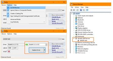
|
Note
|
If you use ATMEL Studio you must ensure the Windows device driver is libusb or libusb-win32.
|
|
Note
|
If you use AVRDUDE then uou must ensure the Windows device driver is libusbK.
|
Next in the process is to upgrade the firmware of the AVRISP MKII.
Option 1:
This process shows the installation of Atmel Studio 7, however, you may have to use Atmel Studio 6 because of operation system constraint.
Download and Install Atmel Studio 7 from the GCBASIC file store here
After the installation open ATMEL STUDIO 7
-
Select Tools / Device Programming
-
Make sure the AVRISP MKII is selected
-
At this point ATMEL STUDIO will notified to upgrade the firmware to version 1.8
-
Click the Upgrade button
-
Once the firmware is upgraded, close ATMEL STUDIO 7
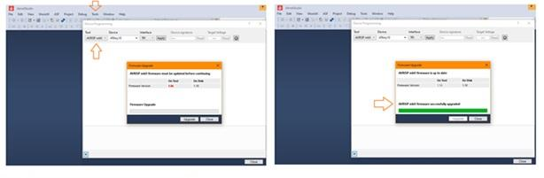
Option 2:
To update the firmware please, follow the steps listed below.
-
Connect the programmer to the USB and with a sharp object (needle or pin) press the upgrade pin - it is in a small hole at the back of the board (this will start the bootloader and will turn off the LED, it will also probably show a new unrecognized device in the device manager for which we will install drivers in step 3)
-
Download and install the latest version of "Atmel Flip" software (it can be downloaded from the Atmel’s web-site, or from the GCBASIC file store here )
-
Open its install folder and update the software of the unrecognized device (usually under the "Other devices" tab) with the drivers from folder named "usb"; the device should now be recognized as AT90USB162 under "libusb-win32" tab
-
Start "Atmel FLIP" and click "Select a target device" → choose AT90USB162
-
Click "Select a Communication Medium" and then USB medium
-
Download the firware and unpack Olimex website or the GCBASIC files store here
-
From "File → load HEX file" choose the latest HEX and click "RUN" in the "Operations Flow" section
-
Disconnect the AVR-ISP-MK2 from the USB and connect it again
For more information about AVR-ISP-MK2 see this guide here
AVRISP MKII to ATTINY10 Connections:
Connect the AVRISP MKII to the ATTINY10 as show in the Diagram.
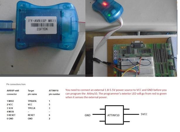
GCStudio Programmer Setup:
Open GCStudio and set the Programmers to use as show below
For AVRISP MKII use the AVR ISP XPII [KANDA] and drag it to the top of the list and click OK.
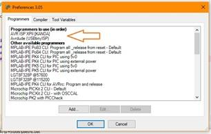
Now you’re ready to upload your first program to an ATTINY10.
USBtinyISP Setup:
-
From Zadig select USBtinyISP in the device list.
-
Select the target driver libusb-win32 and click (Install / Replace Driver) button.
-
After the installation, open Windows Device Manager and verify the driver installation.
-
Close ZADIG
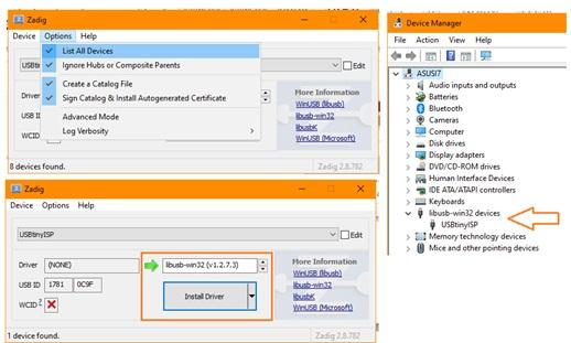
USBtinyISP to ATTINY10 Connections:
Connect the USBtinyISP to the ATTINY10 as show in the Diagram.
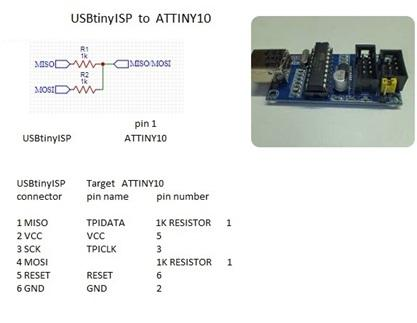
GCStudio Programmer Setup:
Open GCStudio and set the Programmers to use as show below
Select and Drag the Avrdude (USBtinyISP) programmer to the top of the list.
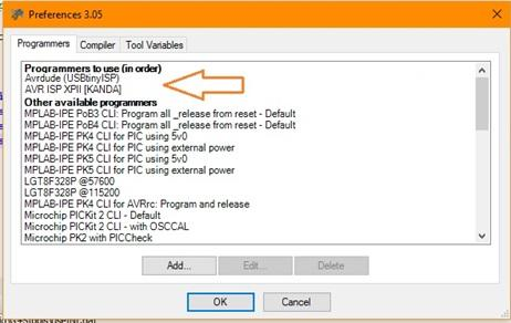
Now you are ready to upload your first program to an ATTINY10
For more information programming review these resources:
A guide http://gcbasic.sourceforge.net/library/Programming_an_Attiny10_with_AVRISP_mkII_and_AVR_Studio_5.pdf[here]
A blog http://gcbasic.sourceforge.net/library/Technoblogy_Programming_the_ATtiny10.pdf[here]